Power Window NISSAN TIIDA 2009 Service Manual PDF
[x] Cancel search | Manufacturer: NISSAN, Model Year: 2009, Model line: TIIDA, Model: NISSAN TIIDA 2009Pages: 4331, PDF Size: 58.04 MB
Page 4040 of 4331

PG
N
O P
Wiring Diagram Codes (Cell Codes)
INFOID:0000000004306667
Use the chart below to find out what each wiring diagram code stands for.
Refer to the wiring diagram code in the alphabetical index to find the location (page number) of each wiring
diagram. D4 D405 W/4 : Back door lock assembly C2 D413 B/1 : Rear window defogger (-)
D4 D406 W/2 : Back door request switch F3 D414 — : Body ground
E2 D407 W/2 : High mounted stop lamp Code Section Wiring Diagram Name
ABS BRC Anti-lock Brake System
A/C,M MTC Manual Air Conditioner
APPS1 EC Accelerator Pe dal Position Sensor
A/F EC Air Fuel Ratio Sensor 1
A/FH EC Air Fuel Ratio Sensor 1 Heater
APPS2 EC Accelerator Pe dal Position Sensor
APPS3 EC Accelerator Pe dal Position Sensor
ASC/BS EC ASCD Brake Switch
ASC/SW EC ASCD Steering Switch
ASCBOF EC ASCD Brake Switch
ASCIND EC ASCD Indicator
AT/IND DI A/T Indicator Lamp
AUDIO AV Audio
BACK/L LT Back-up Lamp
BA/FTS AT A/T Fluid Temperature Sensor and TCM Power Supply
B/DOOR BL Back Door Opener
BRK/SW EC Brake Switch
CAN AT CAN Communication Line
CAN CVT CAN Comm unication Line
CAN EC CAN Communication Line
CAN LAN CAN System
CHARGE SC Charging System
CHIME DI Warning Chime
COOL/F EC Cooling Fan Control
COMBSW LT Combination Switch
CVTIND DI CVT Indicator Lamp
D/LOCK BL Power Door Lock
DEF GW Rear Window Defogger
DTRL LT Headlamp - Wi th Daytime Light System
ECTS EC Engine Coolant Temperature Sensor
ENGSS AT Engine Speed Signal
EPS STC Electronic Controlled Power Steering
ETC1 EC Electric Throttle Control Function
ETC2 EC Throttle Control Motor Relay
ETC3 EC Throttle Control Motor
F/FOG LT Front Fog Lamp
F/PUMP EC Fuel Pump
FTS AT A/T Fluid Temperature Sensor
FTS CVT CVT Fluid Temperature Sensor Circuit
FTTS EC Fuel Tank Temperature Sensor
FUEL EC Fuel Ignition System Function
HEATER MTC Heater System
Page 4042 of 4331

PG
N
O P
STM CVT Step Motor
STOP/L LT Stop Lamp
TCV AT Torque Converter Clutch Solenoid Valve
TCV CVT Torque Converter Clutch Solenoid Valve
T/LID BL Trunk Lid Opener
T/WARN WT Low Tire Pr essure Warning System
TAIL/L LT Parking, License and Tail Lamps
TPS1 EC Throttle Position Sensor
TPS2 EC Throttle Position Sensor
TPS3 EC Throttle Position Sensor
TURN LT Turn Signal and Hazard Warning Lamps
VEHSEC BL Vehicle Security (Theft Warning) System
VENT/V EC EVAP Canister Vent Control Valve
VSSA/T AT Vehicle Speed Sensor A/T (Revolution Sensor)
VSSMTR AT Vehicle Speed Sensor MTR
WARN DI Warning Lamps
WINDOW GW Power Window
WIP/R WW Rear Wiper and Washer
WIPER WW Front Wiper and Washer
Page 4098 of 4331
RF
N
O P
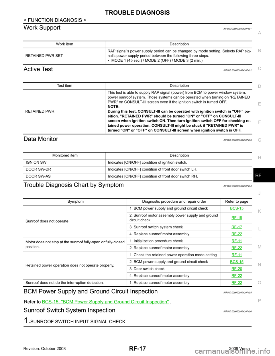
Work Support
INFOID:0000000004307401
Active Test INFOID:0000000004307402
Data Monitor INFOID:0000000004307403
Trouble Diagnosis Chart by Symptom INFOID:0000000004307404
BCM Power Supply and Gr ound Circuit Inspection INFOID:0000000004307405
Refer to BCS-15, " BCM Power Supply and Ground Circuit Inspection " .
Sunroof Switch System Inspection INFOID:0000000004307406Test item Description
RETAINED PWR This test is able to supply RAP signal (power) from BCM to power window system,
power sunroof system. Those systems can be operated when turning on "RETAINED
PWR" on CONSULT-III screen even if the ignition switch is turned OFF.
NOTE:
During this test, CONSULT-III can be operated with ignition switch in "OFF" po-
sition. "RETAINED PWR" should be turned "ON" or "OFF" on CONSULT-III
screen when ignition switch ON. Then turn ignition switch OFF for checking re-
tained power operation. CONSULT-III might be stuck if "RETAINED PWR" is
turned "ON" or "OFF" on CONSULT-III screen when ignition switch is OFF. Symptom Diagnostic procedure and repair order Refer to page
Sunroof does not operate. 1. BCM power supply and ground circuit check
BCS-15 2. Sunroof motor assembly power supply and ground
circuit check RF-19 3. Sunroof switch system check
RF-17 4. Replace sunroof motor assembly
RF-22Motor does not stop at the sunroof fully-open or fully-closed
position. 1. Initialization procedure check
RF-11 2. Replace sunroof motor assembly
RF-22Retained power operation does not operate properly.
1. Check the retained power operation mode setting
RF-11 2. BCM power supply and ground circuit check
BCS-15 3. Door switch check
RF-20 4. Replace sunroof motor assembly
RF-22Sunroof does not do the interruption detection. 1. Replace sunroof motor assembly
RF-22
Page 4144 of 4331
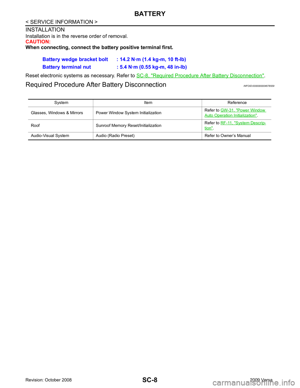
Required Procedure After Battery Disconnection " .
Required Procedure Afte r Battery Disconnection INFOID:0000000004678559
Battery wedge bracket bolt : 14.2 N·m (1.4 kg-m, 10 ft-lb)
Battery terminal nut : 5.4 N·m (0.55 kg-m, 48 in-lb)
System Item Reference
Glasses, Windows & Mirrors Power Window System Initialization Refer to
GW-31, " Power Window
Auto Operation Initialization " .
Roof Sunroof Memory Reset/Initialization Refer to
RF-11, " System Descrip-
tion " .
Audio-Visual System Audio (Radio Preset) Refer to Owner’s Manual