battery NISSAN TIIDA 2009 Service Manual Online
[x] Cancel search | Manufacturer: NISSAN, Model Year: 2009, Model line: TIIDA, Model: NISSAN TIIDA 2009Pages: 4331, PDF Size: 58.04 MB
Page 580 of 4331

BL
N
O P
Trouble Diagnosis Symptom Chart INFOID:0000000004305044
KEY WARNING LAMP (GREEN) ILLUMINATES NOTE: Monitor item Description
CONFIRM KEY FOB ID It can be checked whether Intelligent Key ID code is registered or not in this mode.
TAKE OUT FROM WINDOW
WARN Take away warning chime (from window) mode can be changed to operate (ON) or not operate
(OFF) with this mode. The operation mode will be changed when “CHANGE SETT” on CONSULT-
III screen is touched.
LOW BAT OF KEY FOB WARN Intelligent Key low battery warning mode can be changed to operate (ON) or not operate (OFF)
with this mode. The operation mode will be changed when “CHANGE SETT” on CONSULT-III
screen is touched.
ANSWER BACK FUNCTION Buzzer reminder function mode by Intelligent button can be changed to operate (ON) or not oper-
ate (OFF) with this mode. The operation mode will be changed when “CHANGE SETT” on CON-
SULT-III screen is touched.
SELECTIVE UNLOCK FUNC-
TION Selective unlock function mode can be changed to operate (ON) or not operate (OFF) with this
mode. The operation mode will be changed when “CHANGE SETT” on CONSULT-III screen is
touched.
ANTI KEY LOCK IN FUNCTION Key reminder function mode can be changed to operate (ON) or not operate (OFF) with this mode.
The operation mode will be changed when “CHANGE SETT” on CONSULT-III screen is touched.
HORN WITH KEYLESS LOCK Horn reminder function mode by Intelligent Key remote control button can be changed to operate
(ON) or not operate (OFF) with this mode. The operation mode will be changed when “CHANGE
SETT” on CONSULT-III screen is touched.
HAZARD ANSWER BACK Hazard reminder function mode can be selected from the following with this mode. The operation
mode will be changed when “CHANGE SE TT” on CONSULT-III screen is touched.
• LOCK ONLY: Door lock operation only
• UNLOCK ONLY: Door unlock operation only
• LOCK/UNLOCK: Lock/Unlock operation
• OFF: Non-operation
ANSWER BACK WITH I-KEY
LOCK Buzzer reminder function (lock operation) mode by door request switch (driver side, passenger
side and back door side) can be selected from the following with this mode. The operation mode
will be changed when “ CHANGE SETT” on CONSULT- III screen is touched.
• BUZZER: Sound buzzer
• OFF: Non-operation
ANSWER BACK WITH I-KEY UN-
LOCK Buzzer reminder function (unlock operation) mode by door request switch can be changed to op-
erate (ON) or not operate (OFF) with this mode.
AUTO RELOCK TIMER Auto door lock timer mode can select the following with this mode.
• 1 minute
• OFF: Non-operation
PANIC ALARM DELAY Panic alarm button's pressing time on Intelligent Key remote control button can be selected from
the following with this mode. The operation mode will be changed when “CHANGE SETT” on
CONSULT-III screen is touched.
• 0.5 second
• 1.5 second
• OFF: Non-operation
P/W DOWN DELAY Unlock button's pressing time on Intelligent Key remote control button can be selected from the
following with this mode. The operation mode will be changed when “CHANGE SETT” on CON-
SULT-III screen is touched.
• 3 seconds
• 5 seconds
• OFF: Non-operation
ENGINE START BY I-KEY Engine start function mode can be changed to operate (ON) or not operate (OFF) with this mode.
The operation mode will be changed when “CHANGE SETT” on CONSULT-III screen is touched.
LOCK/UNLOCK BY I-KEY Door lock/unlock function by door request switch (driver side, passenger side and back door side)
mode can be changed to operate (ON) or not operate (OFF) with this mode. The operation mode
will be changed when “ CHANGE SETT” on CONSULT- III screen is touched.
Page 583 of 4331
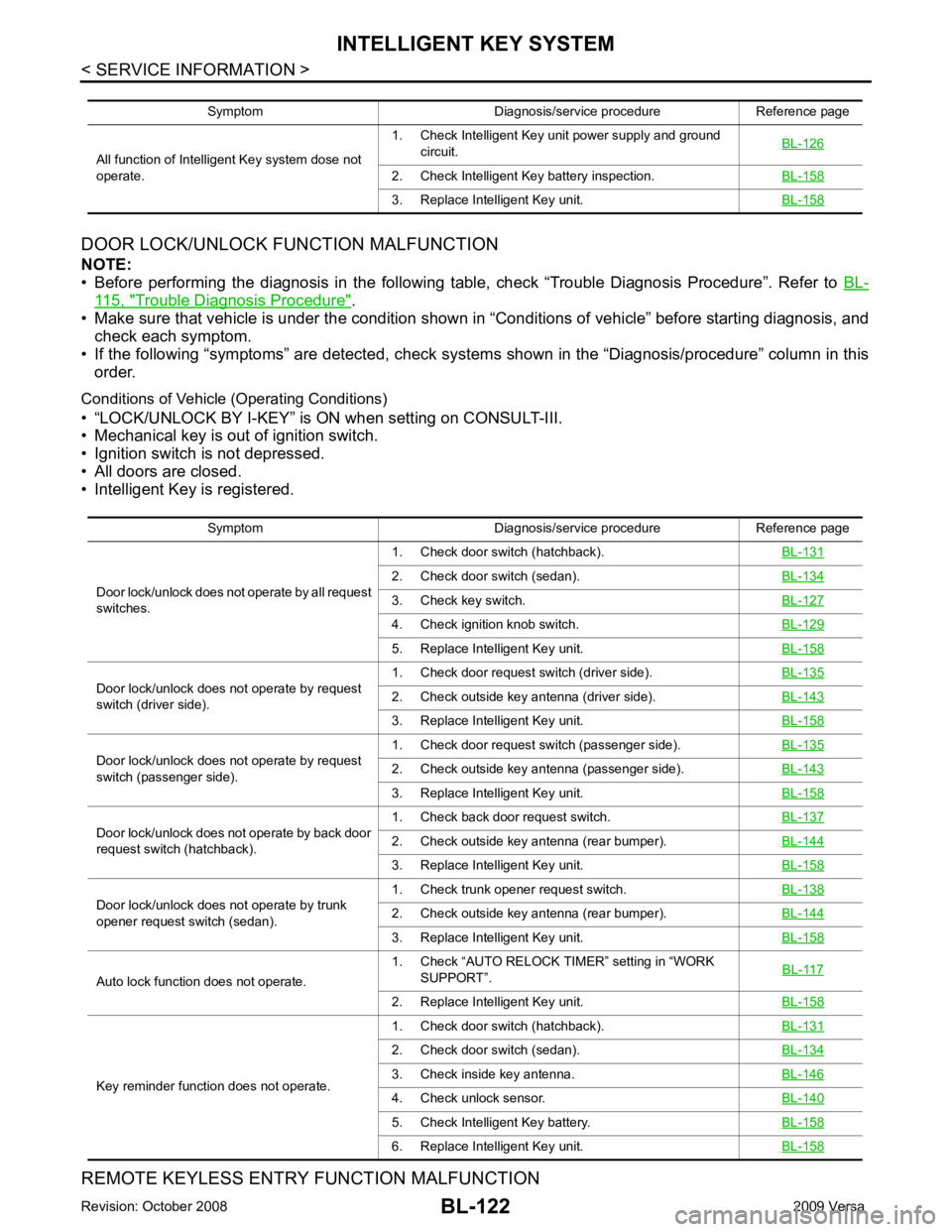
115, " Trouble Diagnosis Procedure " .
• Make sure that vehicle is under the condition shown in “Conditions of vehicle” before starting diagnosis, and
check each symptom.
• If the following “symptoms” are detected, check system s shown in the “Diagnosis/procedure” column in this
order.
Conditions of Vehicle (Operating Conditions)
• “LOCK/UNLOCK BY I-KEY” is ON when setting on CONSULT-III.
• Mechanical key is out of ignition switch.
• Ignition switch is not depressed.
• All doors are closed.
• Intelligent Key is registered.
REMOTE KEYLESS ENTRY FUNCTION MALFUNCTION
Symptom Diagnosis/service procedure Reference page
All function of Intelligent Key system dose not
operate. 1. Check Intelligent Key unit power supply and ground
circuit. BL-126 2. Check Intelligent Key battery inspection.
BL-158 3. Replace Intelligent Key unit.
BL-158Symptom Diagnosis/service procedure Reference page
Door lock/unlock does not operate by all request
switches. 1. Check door switch (hatchback).
BL-131 2. Check door switch (sedan).
BL-134 3. Check key switch.
BL-127 4. Check ignition knob switch.
BL-129 5. Replace Intelligent Key unit.
BL-158Door lock/unlock does not operate by request
switch (driver side). 1. Check door request switch (driver side).
BL-135 2. Check outside key antenna (driver side).
BL-143 3. Replace Intelligent Key unit.
BL-158Door lock/unlock does not operate by request
switch (passenger side). 1. Check door request switch (passenger side).
BL-135 2. Check outside key antenna (passenger side).
BL-143 3. Replace Intelligent Key unit.
BL-158Door lock/unlock does not operate by back door
request switch (hatchback). 1. Check back door request switch.
BL-137 2. Check outside key antenna (rear bumper).
BL-144 3. Replace Intelligent Key unit.
BL-158Door lock/unlock does not operate by trunk
opener request switch (sedan). 1. Check trunk opener request switch.
BL-138 2. Check outside key antenna (rear bumper).
BL-144 3. Replace Intelligent Key unit.
BL-158Auto lock function does not operate.
1. Check “AUTO RELOCK TI
MER” setting in “WORK
SUPPORT”. BL-117 2. Replace Intelligent Key unit.
BL-158Key reminder function does not operate.
1. Check door switch (hatchback).
BL-131 2. Check door switch (sedan).
BL-134 3. Check inside key antenna.
BL-146 4. Check unlock sensor.
BL-140 5. Check Intelligent Key battery.
BL-158 6. Replace Intelligent Key unit.
BL-158
Page 584 of 4331

BL
N
O P
NOTE:
• Before performing the diagnosis in the following table, check “Trouble Diagnosis Procedure”. Refer to BL-115, " Trouble Diagnosis Procedure " .
• Make sure that vehicle is under the condition shown in “Conditions of vehicle” before starting diagnosis, and
check each symptom.
• If the following “symptoms” are detected, check syst ems shown in the “Diagnosis/service procedure” column
in this order.
Conditions of Vehicle (Operating Conditions) • Ignition switch is not depressed.
• All doors are closed.
HAZARD AND BUZZER REMINDER FUNCTION MALFUNCTION NOTE:
• Before performing the diagnosis in the following table, check “Trouble Diagnosis Procedure”. Refer to BL-115, " Trouble Diagnosis Procedure " .
• Make sure that vehicle is under the condition shown in “Conditions of vehicle” before starting diagnosis, and
check each symptom.
• If the following “symptoms” are detected, check syst ems shown in the “Diagnosis/service procedure” column
in this order.
Conditions of Vehicle (Operating Conditions) • Ignition switch is not depressed.
• All doors are closed. Symptom Diagnosis/service procedure
Reference
page
All of the remote keyless entry functions do
not operate. 1. Check Intelligent Key unit power supply and ground circuit.
BL-1262. Check key switch (BCM input).
BL-1283. Check Intelligent Key battery.
BL-1584. Remote Keyless Entry function inspection.
BL-1585. Replace Intelligent Key unit.
BL-158Auto lock function does not operate.
1. Check “AUTO RELOCK TIMER”
setting in “WORK SUPPORT”. BL-117 2. Replace Intelligent Key unit.
BL-158Key reminder function does not operate.
1. Check door switch (hatchback).
BL-1312. Check door switch (sedan).
BL-1343. Check inside key antenna.
BL-1464. Check unlock sensor.
BL-1405. Check Intelligent Key battery.
BL-1586. Replace Intelligent Key unit.
BL-158Panic alarm function does not operate.
1. Check “PANIC ALARM DELAY” setting in “WORK SUPPORT”.
BL-1172. Check Intelligent Key battery inspection.
BL-1583. Check horn function.
BL-1574. Check headlamp function.
BL-1575. Check key switch.
BL-1276. Check ignition knob switch.
BL-1297. Replace Intelligent Key unit.
BL-158Symptom Diagnosis/service procedure Reference page
Hazard reminder does not operate by request
switch.
(Buzzer reminder operate). 1. Check “HAZARD ANSWER BACK” setting in “WORK
SUPPORT”. BL-1172. Check hazard function with hazard switch.
BL-1563. Replace Intelligent Key unit.
BL-158
Page 586 of 4331
BL
N
O P
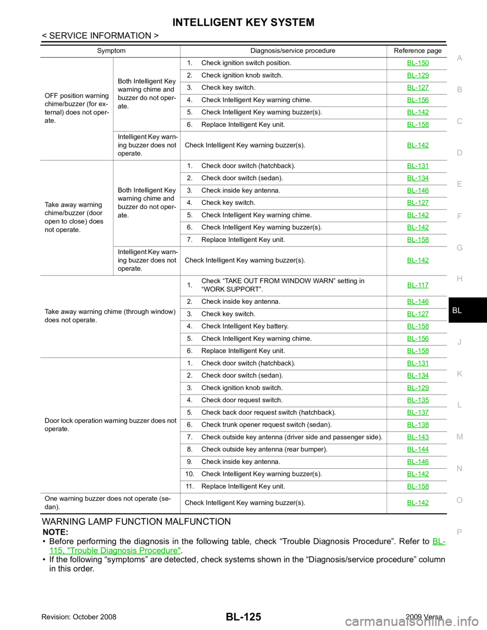
WARNING LAMP FUNCTION MALFUNCTION
NOTE:
• Before performing the diagnosis in the following table, check “Trouble Diagnosis Procedure”. Refer to BL-115, " Trouble Diagnosis Procedure " .
• If the following “symptoms” are detected, check syst ems shown in the “Diagnosis/service procedure” column
in this order.
OFF position warning
chime/buzzer (for ex-
ternal) does not oper-
ate. Both Intelligent Key
warning chime and
buzzer do not oper-
ate. 1. Check ignition switch position.
BL-1502. Check ignition knob switch.
BL-1293. Check key switch.
BL-1274. Check Intelligent Key warning chime.
BL-1565. Check Intelligent Ke
y warning buzzer(s). BL-142 6. Replace Intelligent Key unit.
BL-158Intelligent Key warn-
ing buzzer does not
operate. Check Intelligent Key warning buzzer(s).
BL-142Take away warning
chime/buzzer (door
open to close) does
not operate. Both Intelligent Key
warning chime and
buzzer do not oper-
ate. 1. Check door switch (hatchback).
BL-1312. Check door switch (sedan).
BL-1343. Check inside key antenna.
BL-1464. Check key switch.
BL-1275. Check Intelligent Key warning chime.
BL-1426. Check Intelligent Ke
y warning buzzer(s). BL-142 7. Replace Intelligent Key unit.
BL-158Intelligent Key warn-
ing buzzer does not
operate. Check Intelligent Key warning buzzer(s).
BL-142Take away warning chime (through window)
does not operate. 1.
Check “TAKE OUT FROM WINDOW WARN” setting in
“WORK SUPPORT”. BL-1172. Check inside key antenna.
BL-1463. Check key switch.
BL-1274. Check Intelligent Key battery.
BL-1585. Check Intelligent Key warning chime.
BL-1566. Replace Intelligent Key unit.
BL-158Door lock operation warning buzzer does not
operate. 1. Check door switch (hatchback).
BL-1312. Check door switch (sedan).
BL-1343. Check ignition knob switch.
BL-1294. Check door request switch.
BL-1355. Check back door request switch (hatchback).
BL-1376. Check trunk opener request switch (sedan).
BL-1387. Check outside key antenna (driver side and passenger side).
BL-1438. Check outside key antenna (rear bumper).
BL-1449. Check inside key antenna.
BL-14610. Check Intelligent Key warning buzzer(s).
BL-14211. Replace Intelligent Key unit.
BL-158One warning buzzer does not operate (se-
dan). Check Intelligent Key warning buzzer(s).
BL-142Symptom Diagnosis/service procedure Reference page
Page 587 of 4331
![NISSAN TIIDA 2009 Service Manual Online NO DTC IS DETECT
ED>> Inspection End.
CAN COMM [U1000]>> After printing “SELF-DIAGNOSI S RESULTS”, go to “CAN SYSTEM”. Refer to LAN-17, " Trouble Diagnosis Flow Chart " .
CAN COMM2 [U1010] >>](/img/5/57398/w960_57398-586.png "NISSAN TIIDA 2009 Service Manual Online NO DTC IS DETECT
ED>> Inspection End.
CAN COMM [U1000]>> After printing “SELF-DIAGNOSI S RESULTS”, go to “CAN SYSTEM”. Refer to LAN-17, \" Trouble Diagnosis Flow Chart \" .
CAN COMM2 [U1010] >>")
NO DTC IS DETECT
ED>> Inspection End.
CAN COMM [U1000]>> After printing “SELF-DIAGNOSI S RESULTS”, go to “CAN SYSTEM”. Refer to LAN-17, " Trouble Diagnosis Flow Chart " .
CAN COMM2 [U1010] >> Replace Intelligent Key unit. Refer to BL-158, " Removal and Installation of Intelli-
gent Key Unit " .
Power Supply and Ground Circuit Inspection INFOID:00000000043050462. Check Intelligent Key battery.
BL-158 3. Check KEY warning lamp (green).
BL-155 4. Replace Intelligent Key unit.
BL-158P position warning lamp does not illuminate properly.
(With CVT or A/T) 1. Check CVT or A/T device (park position switch).
BL-153 2. Check “P-SHIFT” warning lamp (red).
BL-154 3. Replace Intelligent Key unit.
BL-158LOCK warning lamp does not illuminate properly.
(With M/T) 1. Check key interlock solenoid.
BL-149 2. Check "LOCK" warning lamp.
BL-155 3. Replace Intelligent Key unit.
BL-158Take away warning lamp does not illuminate properly.
(Take away warning chime is operated). 1. Check KEY warning lamp (red).
BL-158 2. Replace Intelligent Key unit.
BL-158Ignition switch warning lamp does not illuminate properly.
(Ignition switch warning chime is operated). 1. Check KEY warning lamp (red).
BL-155 2. Replace Intelligent Key unit.
BL-158CONSULT-III display item DTC code
NO DTC IS DETECTED — CAN COMM U1000
CAN COMM2 U1010
Page 588 of 4331
BL
N
O P
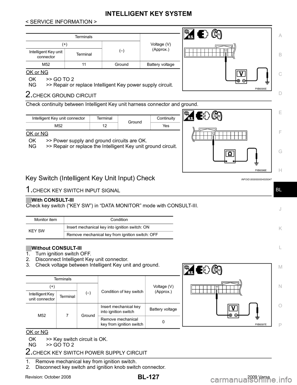
OK or NG OK >> GO TO 2
NG >> Repair or replace Intelligent Key power supply circuit. OK >> Power supply and ground circuits are OK.
NG >> Repair or replace the Intelligent Key unit ground circuit.
Key Switch (Intelligent Key Unit Input) Check INFOID:0000000004305047OK >> Key switch circuit is OK.
NG >> GO TO 2 Terminals
Condition of key switch Voltage (V)
(Approx.)
(+)
(–)
Intelligent Key
unit connector Terminal
M52 7 Ground Insert mechanical key
into ignition switch Battery voltage
Remove mechanical
key from ignition switch 0
Page 590 of 4331
INTELLIGENT KEY SYSTEM
BL-129
< SERVICE INFORMATION >
C
D E
F
G H
J
K L
M A
B BL
N
O P
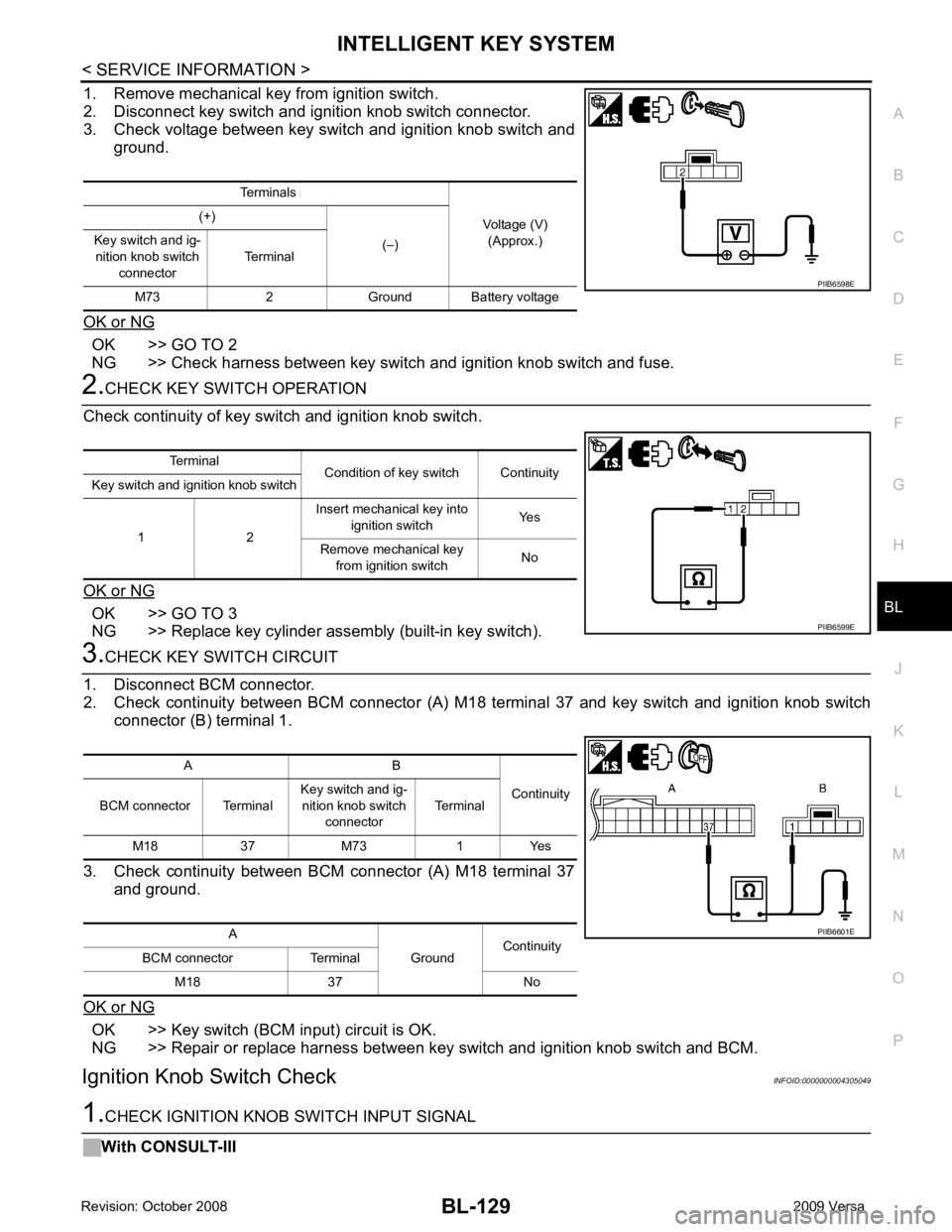
1. Remove mechanical key from ignition switch.
2. Disconnect key switch and i gnition knob switch connector.
3. Check voltage between key switch and ignition knob switch and
ground.
OK or NG OK >> GO TO 2
NG >> Check harness between key switch and ignition knob switch and fuse. 2.
CHECK KEY SWITCH OPERATION
Check continuity of key switch and ignition knob switch.
OK or NG OK >> GO TO 3
NG >> Replace key cylinder assembly (built-in key switch). 3.
CHECK KEY SWITCH CIRCUIT
1. Disconnect BCM connector.
2. Check continuity between BCM connector (A) M18 terminal 37 and key switch and ignition knob switch
connector (B) terminal 1.
3. Check continuity between BCM connector (A) M18 terminal 37 and ground.
OK or NG OK >> Key switch (BCM input) circuit is OK.
NG >> Repair or replace harness between key switch and ignition knob switch and BCM.
Ignition Knob Switch Check INFOID:00000000043050491.
CHECK IGNITION KNOB SWITCH INPUT SIGNAL
With CONSULT-III Terminals
Voltage (V)(Approx.)
(+)
(–)
Key switch and ig-
nition knob switch
connector Terminal
M73 2 Ground Battery voltage PIIB6598E
Terminal
Condition of key switch Continuity
Key switch and ignition knob switch
1 2 Insert mechanical key into
ignition switch Yes
Remove mechanical key from ignition switch No PIIB6599E
A B
Continuity
BCM connector Terminal Key switch and ig-
nition knob switch connector Terminal
M18 37 M73 1 Yes
A GroundContinuity
BCM connector Terminal
M18 37 No PIIB6601E
Page 591 of 4331
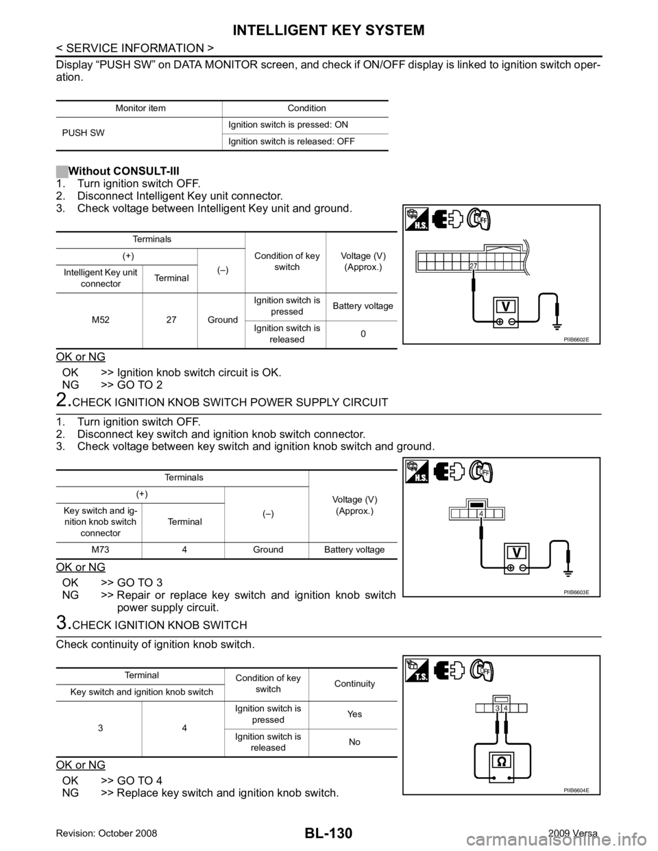
OK >> Ignition knob switch circuit is OK.
NG >> GO TO 2 OK >> GO TO 3
NG >> Repair or replace key switch and ignition knob switch power supply circuit. OK >> GO TO 4
NG >> Replace key switch and ignition knob switch. Monitor item Condition
PUSH SW Ignition switch is pressed: ON
Ignition switch is released: OFF Terminals
Condition of key switch Voltage (V)
(Approx.)
(+)
(–)
Intelligent Key unit
connector Terminal
M52 27 Ground Ignition switch is
pressed Battery voltage
Ignition switch is released 0
Page 593 of 4331
BL-132< SERVICE INFORMATION >
INTELLIGENT KEY SYSTEM
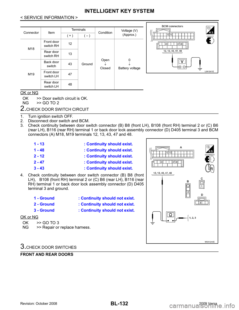
OK or NG OK >> Door switch circuit is OK.
NG >> GO TO 2 2.
CHECK DOOR SWITCH CIRCUIT
1. Turn ignition switch OFF.
2. Disconnect door switch and BCM.
3. Check continuity between door switch connector (B) B8 (front LH), B108 (front RH) terminal 2 or (C) B6
(rear LH), B116 (rear RH) terminal 1 or back door lock assembly connector (D) D405 terminal 3 and BCM
connectors (A) M18, M19 terminals 12, 13, 43, 47 and 48.
4. Check continuity between door switch connector (B) B8 (front
LH), B108 (front RH) terminal 2 or (C) B6 (rear LH), B116 (rear
RH) terminal 1 or back door lock assembly connector (D) D405
terminal 3 and ground.
OK or NG OK >> GO TO 3
NG >> Repair or replace harness. 3.
CHECK DOOR SWITCHES
FRONT AND REAR DOORS Connector Item
Terminals
ConditionVoltage (V)
(Approx.)
( + ) ( – )
M18 Front door
switch RH 12
Ground Open
↓
Closed 0
↓
Battery voltage
Rear door
switch RH 13
M19 Back door
switch 43
Front door switch LH 47
Rear door switch LH 48 LIIA1041E
1 - 13 : Continuity should exist.
1 - 48 : Continuity should exist.
2 - 12 : Continuity should exist.
2 - 47 : Continuity should exist.
3 - 43 : Continuity should exist.
1 - Ground : Continuity should not exist.
2 - Ground : Continuity should not exist.
3 - Ground : Continuity should not exist. WIIA1244E
Page 595 of 4331
BL-134< SERVICE INFORMATION >
INTELLIGENT KEY SYSTEM
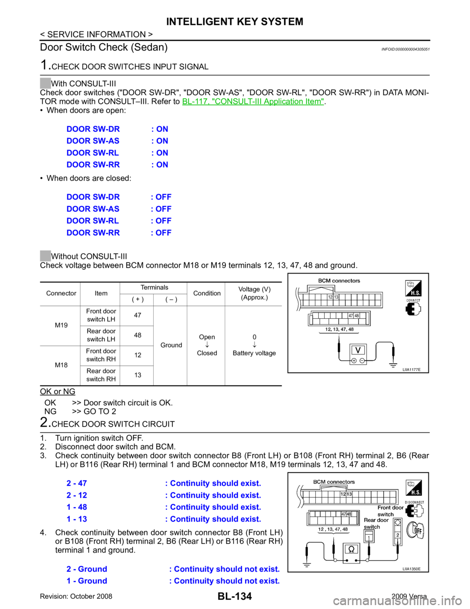
Door Switch Check (Sedan) INFOID:00000000043050511.
CHECK DOOR SWITCHES INPUT SIGNAL
With CONSULT-III
Check door switches ("DOOR SW-DR", "DOOR SW-AS" , "DOOR SW-RL", "DOOR SW-RR") in DATA MONI-
TOR mode with CONSULT–III. Refer to BL-117, " CONSULT-III Application Item " .
• When doors are open:
• When doors are closed:
Without CONSULT-III
Check voltage between BCM connector M18 or M19 terminals 12, 13, 47, 48 and ground.
OK or NG OK >> Door switch circuit is OK.
NG >> GO TO 2 2.
CHECK DOOR SWITCH CIRCUIT
1. Turn ignition switch OFF.
2. Disconnect door switch and BCM.
3. Check continuity between door switch connector B8 (F ront LH) or B108 (Front RH) terminal 2, B6 (Rear
LH) or B116 (Rear RH) terminal 1 and BCM connector M18, M19 terminals 12, 13, 47 and 48.
4. Check continuity between door switch connector B8 (Front LH) or B108 (Front RH) terminal 2, B6 (Rear LH) or B116 (Rear RH)
terminal 1 and ground. DOOR SW-DR : ON
DOOR SW-AS : ON
DOOR SW-RL : ON
DOOR SW-RR : ON
DOOR SW-DR : OFF
DOOR SW-AS : OFF
DOOR SW-RL : OFF
DOOR SW-RR : OFF Connector Item
Terminals
ConditionVoltage (V)
(Approx.)
( + ) ( – )
M19 Front door
switch LH 47
Ground Open
↓
Closed 0
↓
Battery voltage
Rear door
switch LH 48
M18 Front door
switch RH 12
Rear door
switch RH 13 LIIA1177E
2 - 47 : Continuity should exist.
2 - 12 : Continuity should exist.
1 - 48 : Continuity should exist.
1 - 13 : Continuity should exist.
2 - Ground : Continuity should not exist.
1 - Ground : Continuity should not exist. LIIA1350E