height adjustment NISSAN TIIDA 2009 Service Repair Manual
[x] Cancel search | Manufacturer: NISSAN, Model Year: 2009, Model line: TIIDA, Model: NISSAN TIIDA 2009Pages: 4331, PDF Size: 58.04 MB
Page 370 of 4331
AT
N
O P
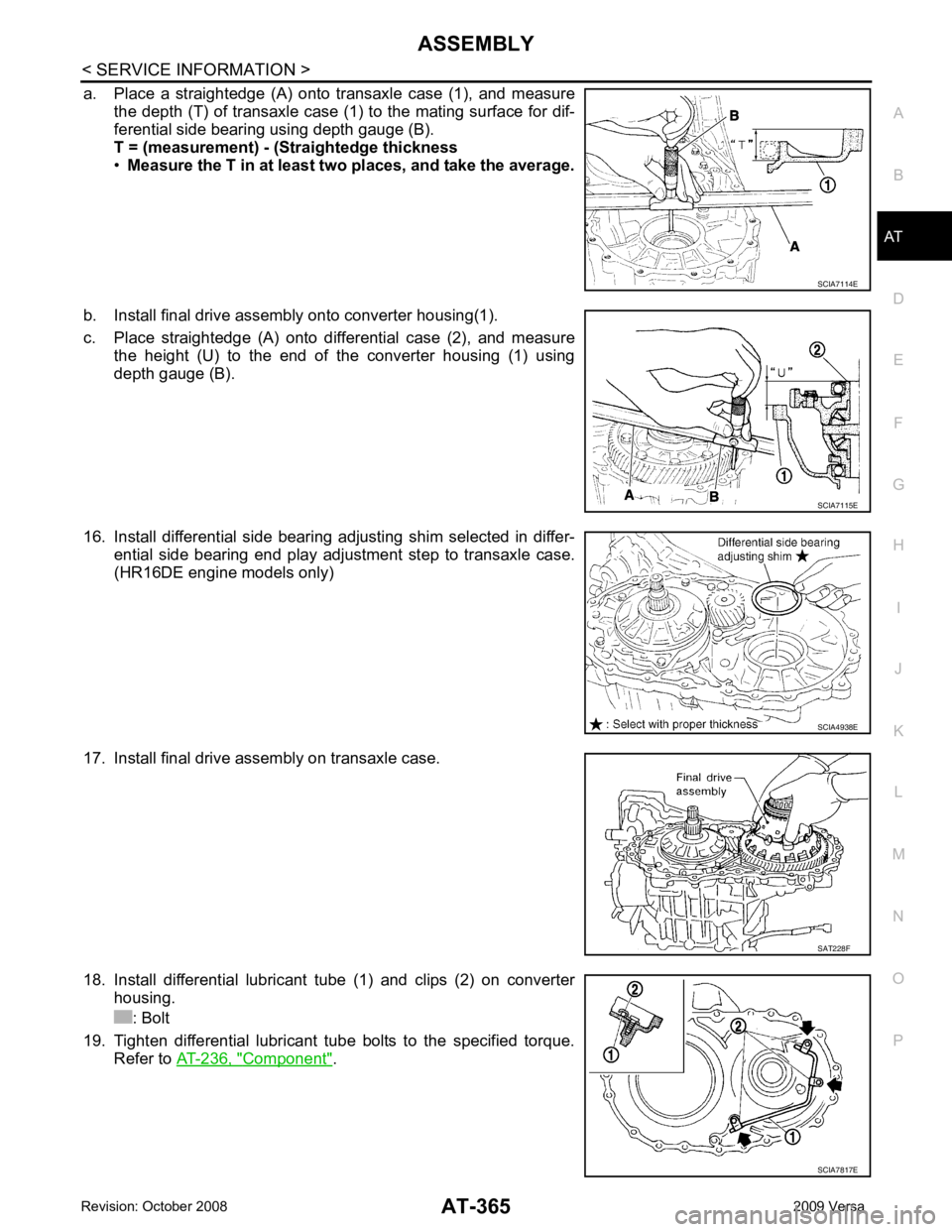
a. Place a straightedge (A) onto tr
ansaxle case (1), and measure
the depth (T) of transaxle case (1) to the mating surface for dif-
ferential side bearing using depth gauge (B).
T = (measurement) - (Straightedge thickness
• Measure the T in at least two places, and take the average.
b. Install final drive assembly onto converter housing(1).
c. Place straightedge (A) onto differential case (2), and measure the height (U) to the end of the converter housing (1) using
depth gauge (B).
16. Install differential side bearing adjusting shim selected in differ- ential side bearing end play adjustment step to transaxle case.
(HR16DE engine models only)
17. Install final drive assembly on transaxle case.
18. Install differential lubricant tube (1) and clips (2) on converter housing.
: Bolt
19. Tighten differential lubricant tube bolts to the specified torque. Refer to AT-236, " Component " .
SCIA7817E
Page 474 of 4331
BL
N
O P
HOOD
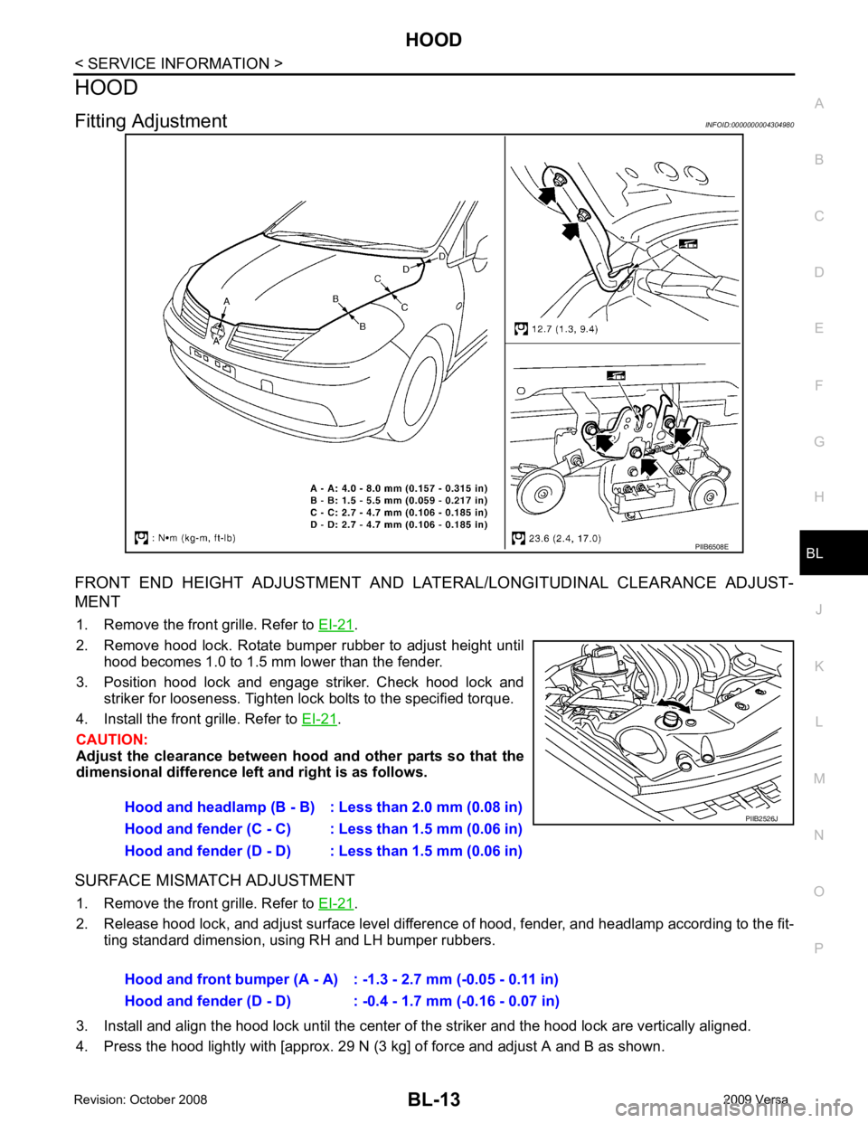
Fitting Adjustment INFOID:0000000004304980
FRONT END HEIGHT ADJUSTMENT AND LA TERAL/LONGITUDINAL CLEARANCE ADJUST-
MENT
1. Remove the front grille. Refer to EI-21 .
2. Remove hood lock. Rotate bumper rubber to adjust height until hood becomes 1.0 to 1.5 mm lower than the fender.
3. Position hood lock and engage striker. Check hood lock and striker for looseness. Tighten lock bolts to the specified torque.
4. Install the front grille. Refer to EI-21 .
CAUTION:
Adjust the clearance between hood and other parts so that the
dimensional difference left and right is as follows.
SURFACE MISMATCH ADJUSTMENT 1. Remove the front grille. Refer to EI-21 .
2. Release hood lock, and adjust surface level difference of hood, fender, and headlamp according to the fit- ting standard dimension, using RH and LH bumper rubbers.
3. Install and align the hood lock until the center of the striker and the hood lock are vertically aligned.
4. Press the hood lightly with [approx. 29 N (3 kg] of force and adjust A and B as shown.
Page 622 of 4331
BL
N
O P
REAR DOOR
Longitudinal Clearance and Surface Height Adjustment at Front End 1. Remove the center pillar upper and lower garnishes. Refer to EI-39 .
2. Access from inside the vehicle to loosen the hinge nuts. Open the rear door, and raise the rear door at
rear end to adjust.
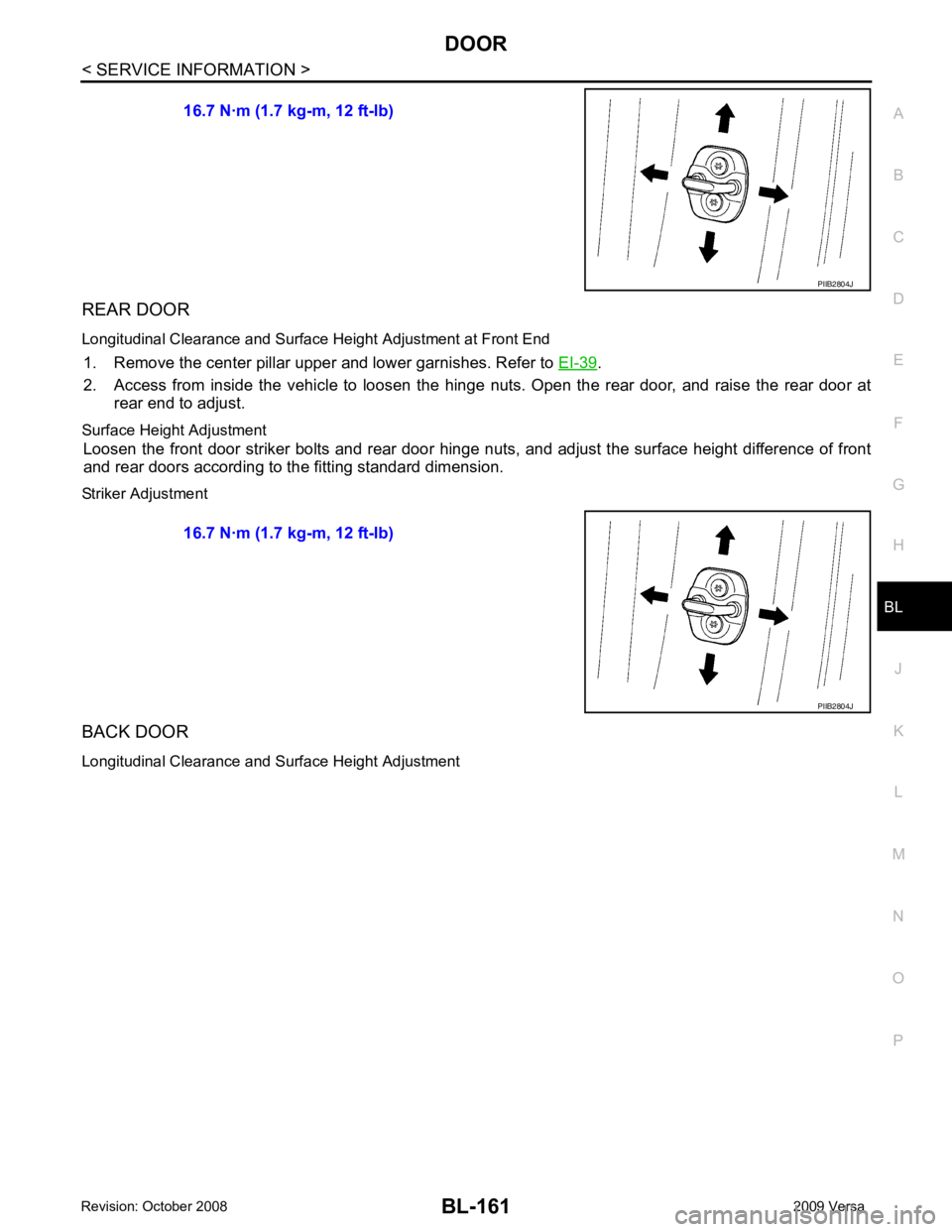
Surface Height Adjustment Loosen the front door striker bolts and rear door hinge nu ts, and adjust the surface height difference of front
and rear doors according to the fitting standard dimension.
Striker Adjustment
BACK DOOR
Longitudinal Clearance and Surface Height Adjustment 16.7 N·m (1.7 kg-m, 12 ft-lb)
Page 654 of 4331
BL
N
O P
TRUNK LID
Fitting Adjustment INFOID:0000000004305097
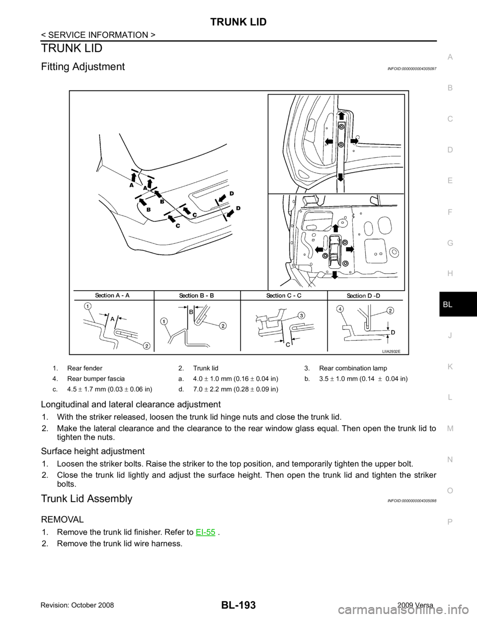
Longitudinal and latera l clearance adjustment
1. With the striker released, loosen the trunk lid hinge nuts and close the trunk lid.
2. Make the lateral clearance and the clearance to the rear window glass equal. Then open the trunk lid to tighten the nuts.
Surface height adjustment 1. Loosen the striker bolts. Raise the striker to t he top position, and temporarily tighten the upper bolt.
2. Close the trunk lid lightly and adjust the surface height. Then open the trunk lid and tighten the striker bolts.
Trunk Lid Assembly INFOID:0000000004305098
REMOVAL 1. Remove the trunk lid finisher. Refer to EI-55 .
2. Remove the trunk lid wire harness. 1. Rear fender 2. Trunk lid 3. Rear combination lamp
4. Rear bumper fascia a. 4.0 ± 1.0 mm (0.16 ± 0.04 in) b. 3.5 ± 1.0 mm (0.14 ± 0.04 in)
c. 4.5 ± 1.7 mm (0.03 ± 0.06 in) d. 7.0 ± 2.2 mm (0.28 ± 0.09 in)
Page 3064 of 4331
EM
NP
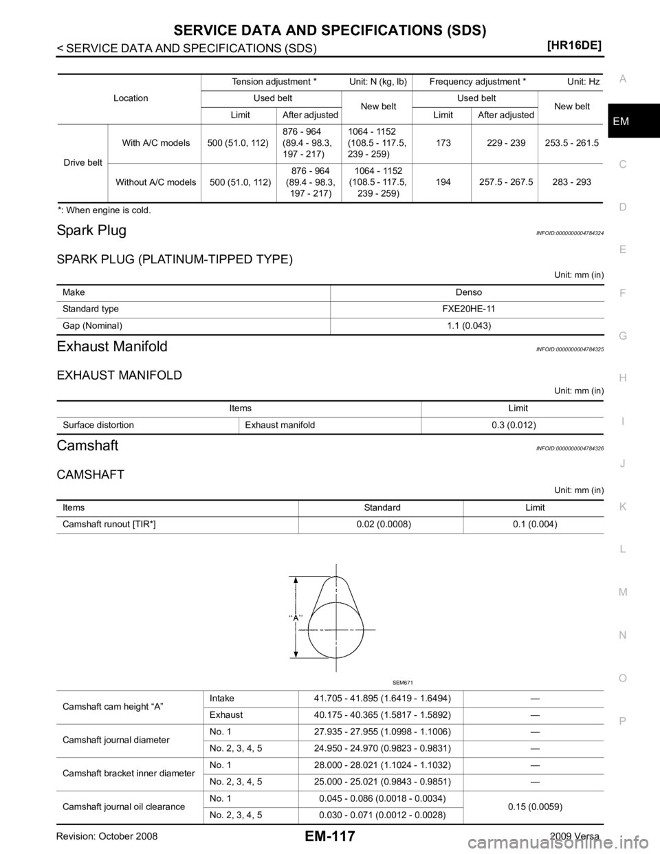
O
*: When engine is cold.
Spark Plug INFOID:0000000004784324
SPARK PLUG (PLATINUM-TIPPED TYPE) Unit: mm (in)
Exhaust Manifold INFOID:0000000004784325
EXHAUST MANIFOLD Unit: mm (in)
Camshaft INFOID:0000000004784326
CAMSHAFT Unit: mm (in)
Location
Tension adjustment * Unit: N (kg, lb) Frequency adjustment * Unit: Hz
Used belt New beltUsed belt
New belt
Limit After adjusted Limit After adjusted
Drive belt With A/C models 500 (51.0, 112)
876 - 964
(89.4 - 98.3,
197 - 217) 1064 - 1152
(108.5 - 117.5,
239 - 259) 173 229 - 239 253.5 - 261.5
Without A/C models 500 (51.0, 112) 876 - 964
(89.4 - 98.3, 197 - 217) 1064 - 1152
(108.5 - 117.5, 239 - 259) 194 257.5 - 267.5 283 - 293Make
Denso
Standard type FXE20HE-11
Gap (Nominal) 1.1 (0.043)Items Limit
Surface distortion Exhaust manifold 0.3 (0.012) Items
Standard Limit
Camshaft runout [TIR*] 0.02 (0.0008) 0.1 (0.004)
Camshaft cam height “A” Intake 41.705 - 41.895 (1.6419 - 1.6494) —
Exhaust 40.175 - 40.365 (1.5817 - 1.5892) —
Camshaft journal diameter No. 1 27.935 - 27.955 (1.0998 - 1.1006) —
No. 2, 3, 4, 5 24.950 - 24.970 (0.9823 - 0.9831) —
Camshaft bracket inner diameter No. 1 28.000 - 28.021 (1.1024 - 1.1032) —
No. 2, 3, 4, 5 25.000 - 25.021 (0.9843 - 0.9851) —
Camshaft journal oil clearance No. 1 0.045 - 0.086 (0.0018 - 0.0034)
0.15 (0.0059)
No. 2, 3, 4, 5 0.030 - 0.071 (0.0012 - 0.0028)
Page 3174 of 4331

EM
NP
O
SERVICE DATA AND SPECIFICATIONS (SDS)
Standard and Limit INFOID:0000000004307162
GENERAL SPECIFICATIONS
DRIVE BELT
WATER CONTROL VALVE
EXHAUST MANIFOLD Unit: mm (in)
THERMOSTAT
SPARK PLUG Unit: mm (in)
CYLINDER HEAD Unit: mm (in)
Engine type
MR18DE
Cylinder arrangement In-line 4
Displacement cm3
(cu in) 1,797 (109.65)
Bore and stroke mm (in) 84.0 x 81.1 (3.307 x 3.192)
Valve arrangement DOHC
Firing order 1-3-4-2
Number of piston rings Compression 2
Oil 1
Compression ratio 9.9
Compression pressure
kPa (bar, kg/cm 2
, psi) / 250 rpm Standard 1,500 (15.0, 15.3, 217.6)
Minimum 1,200 (12.0, 12.2, 174)
Differential limit between cylinders 100 (1.0, 1.0, 15) Tension of drive belt Auto adjustment by auto-tensioner
Valve opening temperature 93.5 - 96.5
°C (200 - 206 °F)
Full-open valve lift amount 8 mm/ 108 °C (0.315 in/ 226 °F)
Valve closing temperature More than 90 °C (194 °F) Items
Limit
Surface distortion Each exhaust port 0.3 (0.012)
Entire part 0.7 (0.028) Valve opening temperature 80.5 - 83.5
°C (177 - 182 °F)
Full-open valve lift amount 8 mm/ 95 °C (0.315 in/ 203 °F)
Valve closing temperature More than 77 °C (171 °F) Make
DENSO
Standard type FXE20HR11
Spark plug gap Nominal: 1.1 (0.043)Items Standard Limit
Head surface distortion — 0.1 (0.004)
Normal cylinder head height (H) 130.9 (5.15) —
Page 3241 of 4331
FSU
N
O P
FRONT SUSPENSION ASSEMBLY
On-Vehicle Inspection and Service INFOID:0000000004305863
Make sure the mounting conditions (looseness, back lash) of each component and component conditions
(wear, damage) are normal.
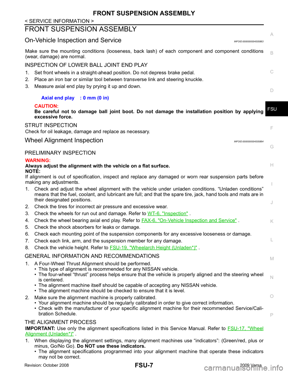
INSPECTION OF LOWER BALL JOINT END PLAY 1. Set front wheels in a straight-ahead position. Do not depress brake pedal.
2. Place an iron bar or similar tool bet ween transverse link and steering knuckle.
3. Measure axial end play by prying it up and down.
CAUTION:
Be careful not to damage ball joint boot. Do not damage the installation position by applying
excessive force.
STRUT INSPECTION Check for oil leakage, damage and replace as necessary.
Wheel Alignment Inspection INFOID:0000000004305864
PRELIMINARY INSPECTION WARNING:
Always adjust the alignment with the vehicle on a flat surface.
NOTE:
If alignment is out of specification, inspect and r eplace any damaged or worn rear suspension parts before
making any adjustments.
1. Check and adjust the wheel alignment with the vehicle under unladen conditions. “Unladen conditions”
means that the fuel, coolant, and lubricant are full; and that the spare tire, jack, hand tools and mats are in
their designated positions.
2. Check the tires for incorrect air pressure and excessive wear.
3. Check the wheels for run out and damage. Refer to WT-6, " Inspection " .
4. Check the wheel bearing axial end play. Refer to FAX-6, " On-Vehicle Inspection and Service " .
5. Check the shock absorbers for leaks or damage.
6. Check each mounting point of the suspension components for any excessive looseness or damage.
7. Check each link, arm, and the suspension member for any damage.
8. Check the vehicle height. Refer to FSU-19, " Wheelarch Height (Unladen*) " .
GENERAL INFORMATION AND RECOMMENDATIONS 1. A Four-Wheel Thrust Alignment should be performed. • This type of alignment is re commended for any NISSAN vehicle.
• The four-wheel “thrust” process helps ensure that the vehicle is properly aligned and the steering wheel
is centered.
• The alignment machine itself should be ca pable of accepting any NISSAN vehicle.
• The alignment machine should be checked to ensure that it is level.
2. Make sure the alignment machine is properly calibrated. • Your alignment machine should be regularly calib rated in order to give correct information.
• Check with the manufacturer of your specific a lignment machine for their recommended Service/Cali-
bration Schedule.
THE ALIGNMENT PROCESS IMPORTANT: Use only the alignment specifications listed in this Service Manual. Refer to FSU-17, " Wheel
Alignment (Unladen*) " .
1. When displaying the alignment settings, many alignm ent machines use “indicators”: (Green/red, plus or
minus, Go/No Go). Do NOT use these indicators.
• The alignment specifications programmed into your alignment machine that operate these indicators
may not be correct. Axial end play : 0 mm (0 in)
Page 4071 of 4331
PS
N
O P
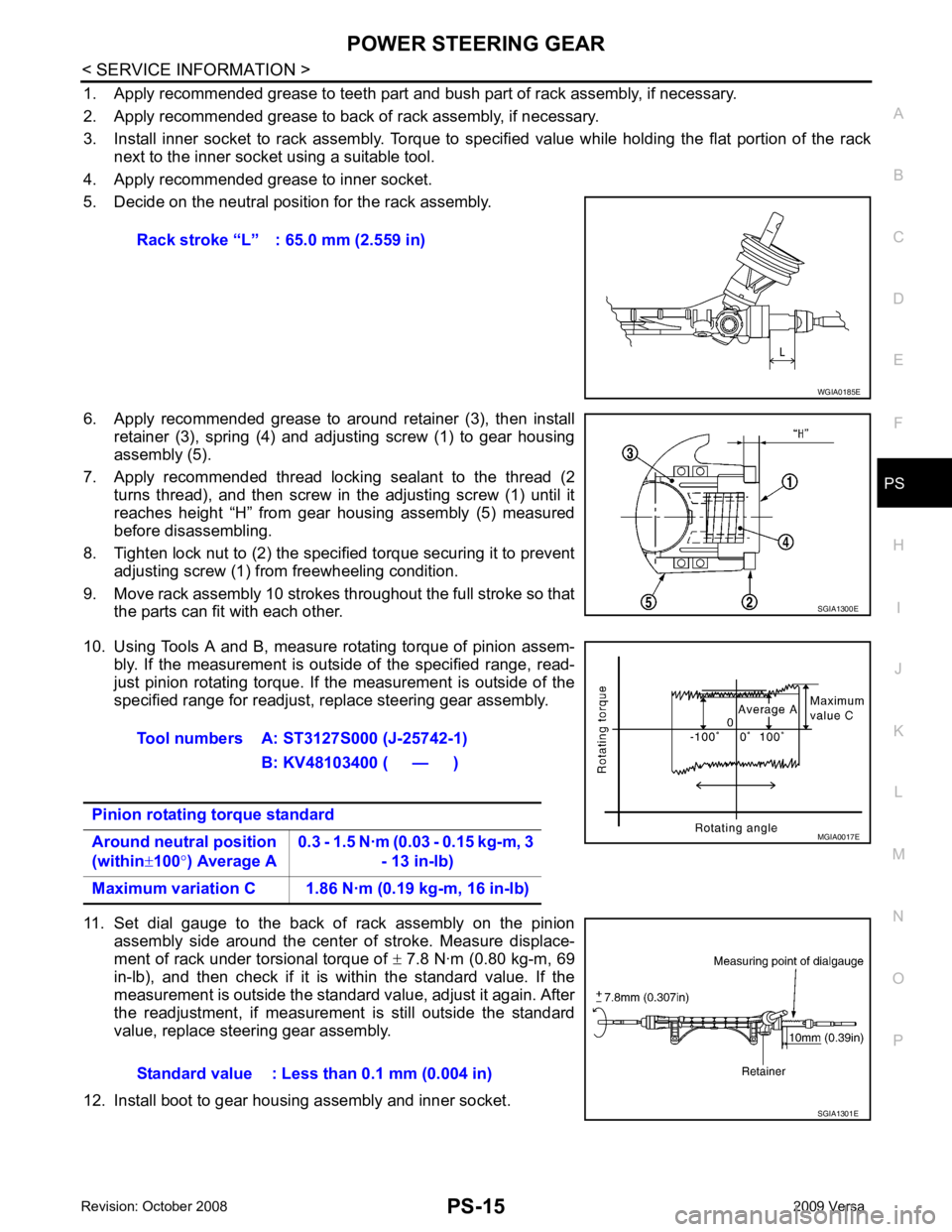
1. Apply recommended grease to teeth part and bush part of rack assembly, if necessary.
2. Apply recommended grease to back of rack assembly, if necessary.
3. Install inner socket to rack assembly. Torque to specified value while holding the flat portion of the rack next to the inner socket using a suitable tool.
4. Apply recommended grease to inner socket.
5. Decide on the neutral position for the rack assembly.
6. Apply recommended grease to around retainer (3), then install retainer (3), spring (4) and adjusting screw (1) to gear housing
assembly (5).
7. Apply recommended thread locking sealant to the thread (2 turns thread), and then screw in the adjusting screw (1) until it
reaches height “H” from gear housing assembly (5) measured
before disassembling.
8. Tighten lock nut to (2) the specified torque securing it to prevent adjusting screw (1) from freewheeling condition.
9. Move rack assembly 10 strokes throughout the full stroke so that the parts can fit with each other.
10. Using Tools A and B, measure rotating torque of pinion assem- bly. If the measurement is outside of the specified range, read-
just pinion rotating torque. If the measurement is outside of the
specified range for readjust, replace steering gear assembly.
11. Set dial gauge to the back of rack assembly on the pinion assembly side around the center of stroke. Measure displace-
ment of rack under torsional torque of ± 7.8 N·m (0.80 kg-m, 69
in-lb), and then check if it is within the standard value. If the
measurement is outside the standard value, adjust it again. After
the readjustment, if measurement is still outside the standard
value, replace steering gear assembly.
12. Install boot to gear housing assembly and inner socket. Rack stroke “L” : 65.0 mm (2.559 in)
Page 4109 of 4331
RF-28< ON-VEHICLE REPAIR >
SUNROOF
HEIGHT ADJUSTMENT
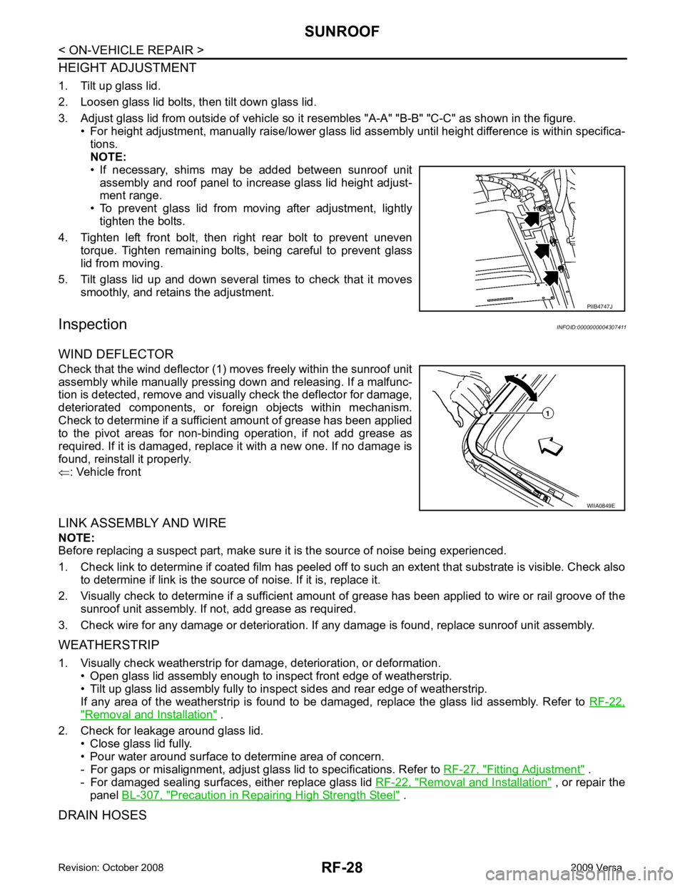
1. Tilt up glass lid.
2. Loosen glass lid bolts, then tilt down glass lid.
3. Adjust glass lid from outside of vehicle so it resembles "A-A" "B-B" "C-C" as shown in the figure.
• For height adjustment, manually raise/lower glass lid assembly until height difference is within specifica-
tions.
NOTE:
• If necessary, shims may be added between sunroof unit
assembly and roof panel to increase glass lid height adjust-
ment range.
• To prevent glass lid from moving after adjustment, lightly
tighten the bolts.
4. Tighten left front bolt, then right rear bolt to prevent uneven torque. Tighten remaining bolts, being careful to prevent glass
lid from moving.
5. Tilt glass lid up and down several times to check that it moves smoothly, and retains the adjustment.
Inspection INFOID:0000000004307411
WIND DEFLECTOR
Check that the wind deflector (1) moves freely within the sunroof unit
assembly while manually pressing down and releasing. If a malfunc-
tion is detected, remove and visually check the deflector for damage,
deteriorated components, or foreign objects within mechanism.
Check to determine if a sufficient amount of grease has been applied
to the pivot areas for non-binding operation, if not add grease as
required. If it is damaged, replace it with a new one. If no damage is
found, reinstall it properly.
⇐ : Vehicle front
LINK ASSEMBLY AND WIRE
NOTE:
Before replacing a suspect part, make sure it is the source of noise being experienced.
1. Check link to determine if coated film has peeled off to such an extent that substrate is visible. Check also
to determine if link is the source of noise. If it is, replace it.
2. Visually check to determine if a sufficient amount of grease has been applied to wire or rail groove of the
sunroof unit assembly. If not, add grease as required.
3. Check wire for any damage or deterioration. If any damage is found, replace sunroof unit assembly.
WEATHERSTRIP
1. Visually check weatherstrip for dam age, deterioration, or deformation.
• Open glass lid assembly enough to inspect front edge of weatherstrip.
• Tilt up glass lid assembly fully to in spect sides and rear edge of weatherstrip.
If any area of the weatherstrip is found to be damaged, replace the glass lid assembly. Refer to RF-22," Removal and Installation " .
2. Check for leakage around glass lid. • Close glass lid fully.
• Pour water around surface to determine area of concern.
- For gaps or misalignment, adjust glass lid to specifications. Refer to RF-27, " Fitting Adjustment " .
- For damaged sealing surfaces, either replace glass lid RF-22, " Removal and Installation " , or repair the
panel BL-307, " Precaution in Repairing High Strength Steel " .
DRAIN HOSES PIIB4747J
WIIA0849E