light NISSAN TIIDA 2009 Service Repair Manual
[x] Cancel search | Manufacturer: NISSAN, Model Year: 2009, Model line: TIIDA, Model: NISSAN TIIDA 2009Pages: 4331, PDF Size: 58.04 MB
Page 8 of 4331

AT
N
O
P
N
Wiring Diagram - AT -
SSV/B ................................
145
Diagnosis Procedure ........................................... ..146
Component Inspection ........................................ ..147
DTC P1760 OVERRUN CLUTCH SOLENOID
VALVE ............................................................ ..149
Description .......................................................... ..149
CONSULT-III Refe rence Value in Data Monitor
Mode ................................................................... ..
149
On Board Diagnosis Logic .................................. ..149
Possible Cause ................................................... ..149
DTC Confirmation Procedure .............................. ..149
Wiring Diagram - AT - OVRCSV ......................... ..150
Diagnosis Procedure ........................................... ..151
Component Inspection ........................................ ..152
DTC VEHICLE SPEED SENSOR MTR .......... ..154
Description .......................................................... ..154
CONSULT-III Refe rence Value in Data Monitor
Mode ................................................................... ..
154
On Board Diagnosis Logic .................................. ..154
Possible Cause ................................................... ..154
DTC Confirmation Procedure .............................. ..154
Wiring Diagram - AT - VSSMTR ...........................155
Diagnosis Procedure ........................................... ..156
DTC BATT/FLUID TEMP SEN (A/T FLUID
TEMP SENSOR CIRCUIT AND TCM POWER
SOURCE) ....................................................... ..
157
Description .......................................................... ..157
CONSULT-III Refe rence Value in Data Monitor
Mode ................................................................... ..
157
On Board Diagnosis Logic .................................. ..157
Possible Cause ................................................... ..157
DTC Confirmation Procedure .............................. ..157
Wiring Diagram - AT - BA/FTS ............................ ..158
Diagnosis Procedure ........................................... ..159
Component Inspection ........................................ ..161
DTC TURBINE REVOLUTION SENSOR ....... ..163
Description .......................................................... ..163
CONSULT-III Refe rence Value in Data Monitor
Mode ................................................................... ..
163
On Board Diagnosis Logic .................................. ..163
Possible Cause ................................................... ..163
DTC Confirmation Procedure .............................. ..163
Wiring Diagram - AT - PT/SEN ........................... ..164
Diagnosis Procedure ........................................... ..165
CONTROL UNIT (RAM), CONTROL UNIT
(ROM) ............................................................. ..
168
Description .......................................................... ..168
On Board Diagnosis Logic .................................. ..168
Possible Cause ................................................... ..168
DTC Confirmation Procedure .............................. ..168
Diagnosis Procedure ........................................... ..168
MAIN POWER SUPPLY AND GROUND CIR-
CUIT ................................................................ ..169
Wiring Diagram - AT - MAIN ............................... ..169 Diagnosis Procedure ...........................................
..170
PNP, OD SWITCH AND CLOSED THROT-
TLE, WIDE OPEN THROTTLE POSITION
SIGNAL CIRCUI T ............................................ 172
CONSULT-III Reference Va lue in Data Monitor
Mode .................................................................... ..
172
TCM Terminal and Refere nce Value .....................172
Diagnosis Procedure ........................................... ..172
Component Inspection ......................................... ..176
SHIFT POSITION INDICATOR CIRCUIT ........ 177
Description ........................................................... ..177
CONSULT-III Reference Va lue in Data Monitor
Mode .................................................................... ..
177
Diagnosis Procedure ........................................... ..177
TROUBLE DIAGNOSIS FOR SYMPTOMS .... 178
Wiring Diagram - AT - NONDTC ......................... ..178
OD OFF Indicator Lamp Does Not Come On ...... ..181
Engine Cannot Be Started in "P" and "N" Position ..183
In "P" Position, Vehicle Moves Forward or Back-
ward When Pushed ............................................. ..
184
In "N" Position, Vehicle Moves ............................ ..184
Large Shock "N" → "R" Position .......................... ..185
Vehicle Does Not Creep Backward in "R" Position ..186
Vehicle Does Not Creep Forw ard in "D", "2" or "1"
Position ................................................................ ..
187
Vehicle Cannot Be Started from D 1 ..................... ..188
A/T Does Not Shift: D 1→ D 2or Does Not Kick-
down: D 4→ D 2 ..................................................... ..190
A/T Does Not Shift: D 2→ D 3 ................................ ..192
A/T Does Not Shift: D 3→ D 4 ................................ ..193
A/T Does Not Perform Lock-up ........................... ..194
A/T Does Not Hold Lock-up Condition ................. ..195
Lock-up Is Not Released ..................................... ..196
Engine Speed Does Not Return to Idle (Light
Braking D 4→ D 3) ................................................. ..197
A/T Does Not Shift: D 4→ D 3, When OD OFF ...... ..198
A/T Does Not Shift: D 3→ 22, When Selector Lever
"D" → "2" Position ............................................... ..
199
A/T Does Not Shift: 2 2→ 11, When Selector Lever
"2" → "1" Position ................................................ ..
200
Vehicle Does Not Decelerate by Engine Brake ... ..202
TCM Self-Diagnosis Does Not Activate ............... ..205
A/T SHIFT LOCK SYSTEM ............................. 207
Description ........................................................... ..207
Shift Lock System Parts Location ........................ ..207
Wiring Diagram - AT - SHIFT .............................. ..208
Diagnosis Procedure ........................................... ..208
TRANSMISSION CONTROL MODULE .......... 211
Removal and Installation ..................................... ..211
SHIFT CONTROL SYSTEM ............................ 212
Control Device Removal an d Installation ...............212
Control Device Disassembly and Assembly ..........215
Selector Lever Knob Remo val and Installation ......215
Adjustment of A/T Position .................................. ..216
Page 46 of 4331
AT
N
O P
The OD OFF indicator lamp is located on the combination meter.
1. If the ignition switch stays ON after repair work, be su re to turn ignition switch OFF once. Wait at least 10
seconds and then turn it ON (engine stopped) again.
2. Perform “TCM SELF-DIAGNOSTIC PR OCEDURE (No Tools)”. Refer to AT-83, " Diagnosis Procedure
without CONSULT-III " . (The engine warm-up step can be ski
pped when performing the diagnosis only to
erase the DTC.)
3. Perform “OBD-II SELF-DIAGNOSTIC PROCEDURE (No tools)”. Refer to EC-90, " Diagnosis Description "
(HR16DE),
EC-542, " Emission-related Diagnostic Information " (MR Type 1) or
EC-1052, " Emission-
related Diagnostic Information " (MR Type 2).
Malfunction Indicator Lamp (MIL) INFOID:0000000004305313
DESCRIPTION The MIL is located on the instrument panel.
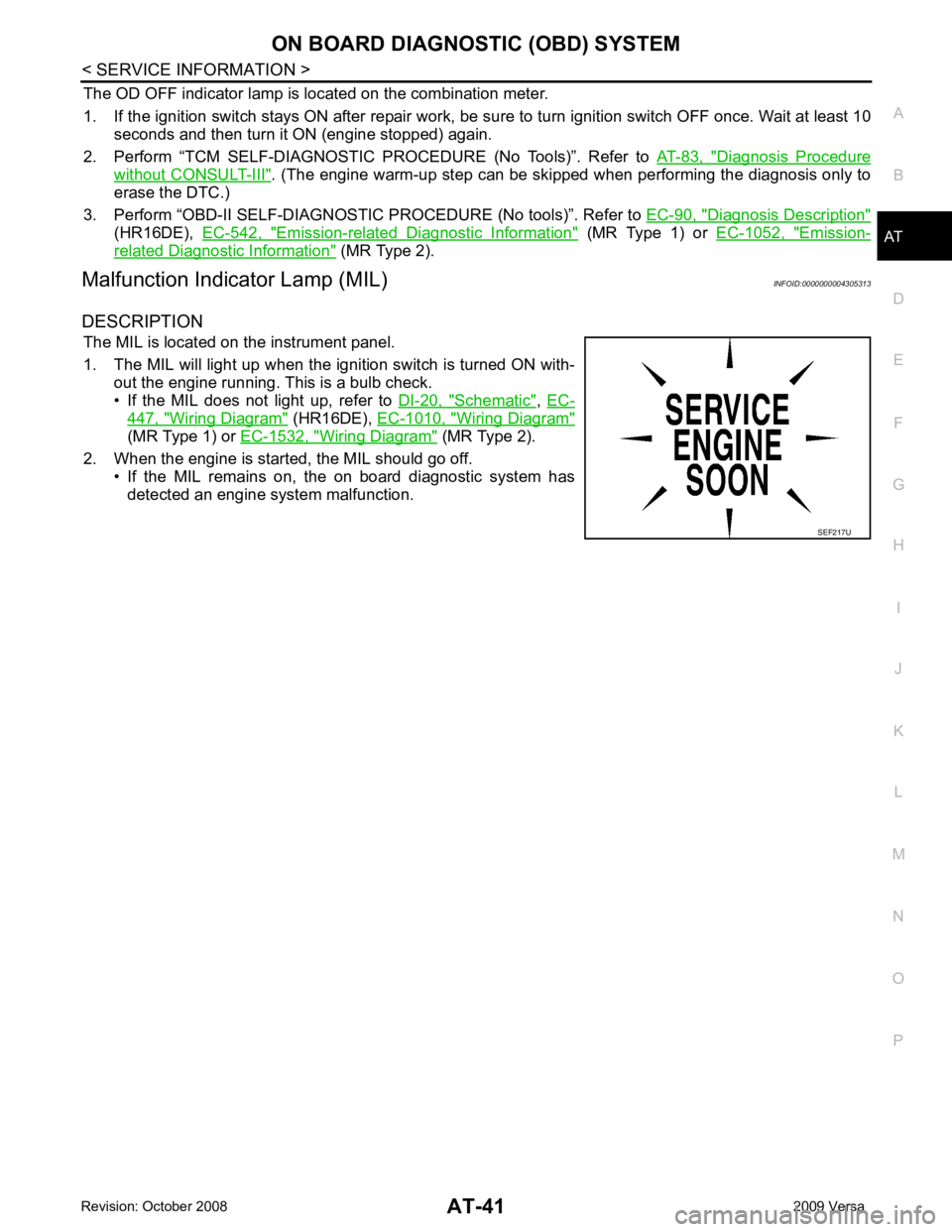
1. The MIL will light up when the ignition switch is turned ON with- out the engine running. This is a bulb check.
• If the MIL does not light up, refer to DI-20, " Schematic " ,
EC- 447, " Wiring Diagram " (HR16DE),
EC-1010, " Wiring Diagram "
(MR Type 1) or
EC-1532, " Wiring Diagram " (MR Type 2).
2. When the engine is start ed, the MIL should go off.
• If the MIL remains on, the on board diagnostic system has
detected an engine system malfunction.
Page 53 of 4331
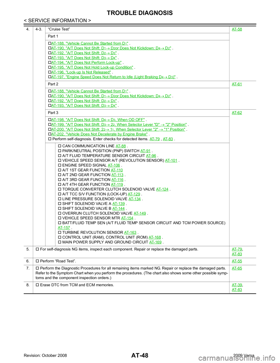
Part 1
�† AT-188, " Vehicle Cannot Be Started from D .
�† AT-190, " A/T Does Not Shift: D .
�† AT-192, " A/T Does Not Shift: D .
�† AT-193, " A/T Does Not Shift: D .
�† AT-194, " A/T Does Not Perform Lock-up " .
�† AT-195, " A/T Does Not Hold
Lock-up Condition " .
�† AT-196, " Lock-up Is Not Released " .
�† AT-197, " Engine Speed Does Not Return to Idle (Light Braking D " .
Part 2 AT-61Vehicle Cannot Be Started from D .
�† AT-190, " A/T Does Not Shift: D .
�† AT-192, " A/T Does Not Shift: D .
�† AT-193, " A/T Does Not Shift: D .
Part 3 AT-62A/T Does Not Shift: D " .
�† AT-199, " A/T Does Not Shift: D " .
�† AT-200, " A/T Does Not Shift: 2 " .
�† AT-202, " Vehicle Does Not Decelerate by Engine Brake " .
�† Perform self-diagnosis. Enter checks for detected items. AT-79 ,
AT-83 .
�† CAN COMMUNICATION LINE AT-88 .
�† PARK/NEUTRAL POSITION (PNP) SWITCH AT-91 .
�† A/T FLUID TEMPERATURE SENSOR CIRCUIT AT-96 .
�† VEHICLE SPEED SENSOR A/T (REVOLUTION SENSOR) AT-101 .
�† ENGINE SPEED SIGNAL AT-106 .
�† A/T 1ST GEAR FUNCTION AT-110 .
�† A/T 3RD GEAR FUNCTION AT-116 .
�† A/T 4TH GEAR FUNCTION AT-119 .
�† TORQUE CONVERTER CLUTCH SOLENOID VALVE AT-124 .
�† A/T TCC S/V FUNCTION (LOCK-UP) AT-129 .
�† LINE PRESSURE SOLENOID VALVE AT-134 .
�† SHIFT SOLENOID VALVE A AT-139 .
�† SHIFT SOLENOID VALVE B AT-144 .
�† OVERRUN CLUTCH SOLENOID VALVE AT-149 .
�† VEHICLE SPEED SENSOR MTR AT-154 .
�† BATT/FLUID TEMP SEN (A/T FLUID TEMP SENSOR CIRCUIT AND TCM POWER SOURCE)
AT-157 .
�† TURBINE REVOLUTION SENSOR AT-163 .
�† CONTROL UNIT (RAM), CONTROL UNIT (ROM) AT-168 .
�† MAIN POWER SUPPLY AND GROUND CIRCUIT AT-169 .
5. �† For self-diagnosis NG items, inspect each component. Repair or replace the damaged parts. AT-79 ,
AT-83 6.
�† Perform “Road Test”. AT-557.
�† Perform the Diagnostic Procedures for all remaining items marked NG. Repair or replace the damaged parts.
Refer to the Symptom Chart when you perform the procedures. (The chart also shows some other possible symp-
toms and the component inspection orders.) AT-658.
�† Erase DTC from TCM and ECM memories. AT-39 ,
AT-83
Page 66 of 4331
TROUBLE DIAGNOSIS
AT-61
< SERVICE INFORMATION >
D
E
F
G H
I
J
K L
M A
B AT
N
O P
• Continue “Road Test”. 8.
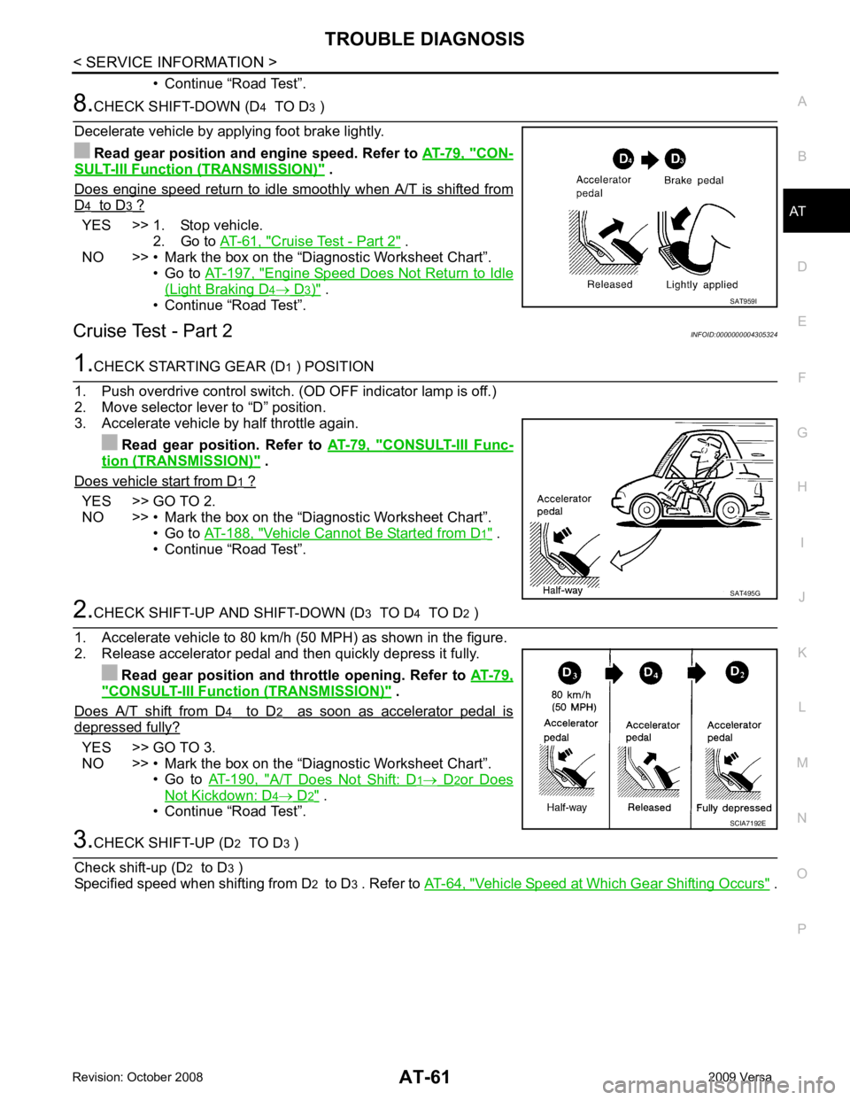
CHECK SHIFT-DOWN (D 4 TO D 3 )
Decelerate vehicle by applying foot brake lightly. Read gear position and engine speed. Refer to AT-79, " CON-
SULT-III Functi
on (TRANSMISSION) " .
Does engine speed return to idle smoothly when A/T is shifted from D 4 to D 3 ?
YES >> 1. Stop vehicle.
2. Go to AT-61, " Cruise Test - Part 2 " .
NO >> • Mark the box on the “D iagnostic Worksheet Chart”.
• Go to AT-197, " Engine Speed Does Not Return to Idle
(Light Braking D 4 → D 3 ) " .
• Continue “Road Test”.
Cruise Test - Part 2 INFOID:00000000043053241.
CHECK STARTING GEAR (D 1 ) POSITION
1. Push overdrive control switch. (OD OFF indicator lamp is off.)
2. Move selector lever to “D” position.
3. Accelerate vehicle by half throttle again.
Read gear position. Refer to AT-79, " CONSULT-III Func-
tion (TRANSMISSION) " .
Does vehicle start from D 1 ?
YES >> GO TO 2.
NO >> • Mark the box on the “D iagnostic Worksheet Chart”.
• Go to AT-188, " Vehicle Cannot Be Started from D 1 " .
• Continue “Road Test”. 2.
CHECK SHIFT-UP AND SHIFT-DOWN (D 3 TO D 4 TO D 2 )
1. Accelerate vehicle to 80 km/h (50 MPH) as shown in the figure.
2. Release accelerator pedal and then quickly depress it fully.
Read gear position and th rottle opening. Refer to AT-79," CONSULT-III Function (TRANSMISSION) " .
Does A/T shift from D 4 to D 2 as soon as accelerator pedal is
depressed fully?
YES >> GO TO 3.
NO >> • Mark the box on the “D iagnostic Worksheet Chart”.
• Go to AT-190, " A/T Does Not Shift: D 1 → D 2 or Does
Not Kickdown: D 4 → D 2 " .
• Continue “Road Test”. 3.
CHECK SHIFT-UP (D 2 TO D 3 )
Check shift-up (D 2 to D 3 )
Specified speed when shifting from D 2 to D 3 . Refer to AT-64, " Vehicle Speed at Which Gear Shifting Occurs " .SAT959I
SAT495G
SCIA7192E
Page 84 of 4331
AT
N
O P
*1
: These terminals are connected to the data link connector.
*2 : These terminals are connected to the ECM.
CONSULT-III Function (TRANSMISSION) INFOID:0000000004305330
CONSULT-III can display each diagnostic item using the diagnostic test models shown following.
FUNCTION
CONSULT-III REFERENCE VALUE NOTICE:
1. The CONSULT-III electrically displays shift timi ng and lock-up timing (that is, operation timing of each
solenoid).
Check for time difference between actual shift timi ng and the CONSULT-III display. If the difference is
noticeable, mechanical parts (except solenoids, sens ors, etc.) may be malfunctioning. Check mechanical
parts using applicable diagnostic procedures.
2. Shift schedule (which implies gear position) display ed on CONSULT-III and that indicated in Service Man-
ual may differ slightly. This occurs because of the following reasons:
- Actual shift schedule has more or less tolerance or allowance,
- Shift schedule indicated in Service Manual re fers to the point where shifts start, and
- Gear position displayed on CONSULT-III indicates the point where shifts are completed.
3. Shift solenoid valve “A” or “B” is displayed on CONSUL T-III at the start of shifting. Gear position is dis-
played upon completion of shifting (which is computed by TCM).
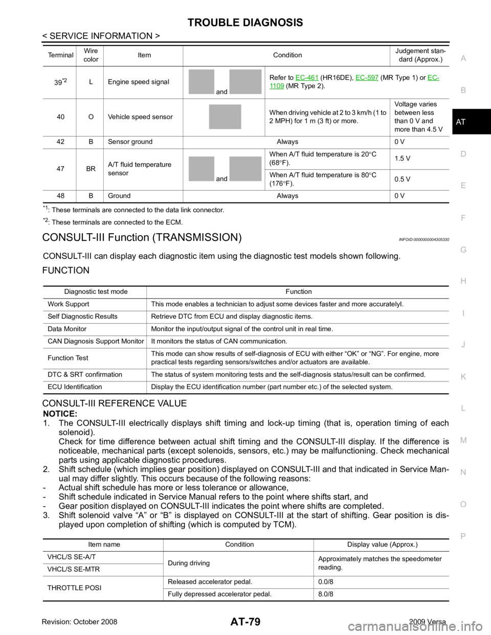
39
*2
L Engine speed signal
and Refer to
EC-461 (HR16DE),
EC-597 (MR Type 1) or
EC- 1109 (MR Type 2).
40 O Vehicle speed sensor When driving vehicle at 2 to 3 km/h (1 to
2 MPH) for 1 m (3 ft) or more. Voltage varies
between less
than 0 V and
more than 4.5 V
42 B Sensor ground Always 0 V
47 BR A/T fluid temperature
sensor and When A/T fluid temperature is 20
°C
(68 °F). 1.5 V
When A/T fluid temperature is 80 °C
(176 °F). 0.5 V
48 B Ground Always 0 V
Terminal
Wire
color Item Condition Judgement stan-
dard (Approx.) Diagnostic test mode Function
Work Support This mode enables a technician to adjust some devices faster and more accuratelyI.
Self Diagnostic Results Retrieve DTC from ECU and display diagnostic items.
Data Monitor Monitor the input/output signal of the control unit in real time.
CAN Diagnosis Support Monitor It monitors the status of CAN communication.
Function Test This mode can show results of self-diagnosis of ECU with either “OK” or “NG”. For engine, more
practical tests regarding sensors/switches and/or actuators are available.
DTC & SRT confirmation The status of system monitoring tests and the self-diagnosis status/result can be confirmed.
ECU Identification Display the ECU identification number (part number etc.) of the selected system. Item name Condition Display value (Approx.)
VHCL/S SE-A/T During driving Approximately matches the speedometer
reading.
VHCL/S SE-MTR
THROTTLE POSI Released accelerator pedal. 0.0/8
Fully depressed accelerator pedal. 8.0/8
Page 89 of 4331
AT-84< SERVICE INFORMATION >
TROUBLE DIAGNOSIS
Description
If a malfunction occurs in electrical system, turning igni tion switch ON will illuminate OD OFF indicator lamp for
2 seconds. To detect a malfunction, entering a self-diagnosis start signal retrieves information on malfunctions
from memory and indicates malfunction by blinking OD OFF indicator lamp.
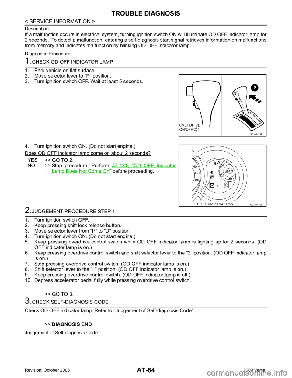
Diagnostic Procedure 1.
CHECK OD OFF INDICATOR LAMP
1. Park vehicle on flat surface.
2. Move selector lever to “P” position.
3. Turn ignition switch OFF. Wait at least 5 seconds.
4. Turn ignition switch ON. (Do not start engine.)
Does OD OFF indicator lamp come on about 2 seconds? YES >> GO TO 2.
NO >> Stop procedure. Perform AT-181, " OD OFF Indicator
Lamp Does Not Come On " before proceeding.
2.
JUDGEMENT PROCEDURE STEP 1
1. Turn ignition switch OFF.
2. Keep pressing shift lock release button.
3. Move selector lever from “P” to “D” position.
4. Turn ignition switch ON. (Do not start engine.)
5. Keep pressing overdrive control switch while OD OF F indicator lamp is lighting up for 2 seconds. (OD
OFF indicator lamp is on.)
6. Keep pressing overdrive control switch and shift select or lever to the “2” position. (OD OFF indicator lamp
is on.)
7. Stop pressing overdrive control switch. (OD OFF indicator lamp is on.)
8. Shift selector lever to the “1” position. (OD OFF indicator lamp is on.)
9. Keep pressing overdrive control switch. (OD OFF indicator lamp is off.)
10. Depress accelerator pedal fully while pressing overdrive control switch.
>> GO TO 3. 3.
CHECK SELF-DIAGNOSIS CODE
Check OD OFF indicator lamp. Refer to "Judgement of Self-diagnosis Code" .
>>DIAGNOSIS END
Judgement of Self-diagnosis Code SCIA5472E
SCIA7140E
Page 202 of 4331
AT
N
O P
Check again. Refer to
AT-58, " Cruise Test - Part 1 " .
OK or NG OK >>
INSPECTION END
NG >> GO TO 3. TCM Terminal and Reference Value " .
2. If NG, recheck TCM pin terminals for dam age or loose connection with harness connector.
OK or NG OK >>
INSPECTION END
NG >> Repair or replace damaged parts.
Engine Speed Does Not Return to Idle (Light Braking D4→ D 3) INFOID:0000000004305486
SYMPTOM: Engine speed does not smoothly return to idle when A/T shifts from D4 to D 3 on “Cruise Test — Part
1”.
DIAGNOSTIC PROCEDURE CONSULT-III Functi
on (TRANSMISSION) " or
AT-83, " Diagnosis Pro-
cedure without CONSULT-III " .
Is any malfunction detected by self-diagnostic results? YES >> Check the malfuncti
oning system. Refer to AT-79, " CONSULT-III Functi
on (TRANSMISSION) " or
AT-83, " Diagnosis Procedure without CONSULT-III " .
NO >> GO TO 2. Description " (HR16DE),
EC-959, " Component
Description " (MR Type 1) or
EC-1481, " Component Description " (MR Type 2).
OK or NG OK >> GO TO 3.
NG >> Repair or replace accelerator pedal position sensor. Component " .
2. Check A/T fluid condition. Refer to AT-51, " Inspections Before Trouble Diagnosis " .
OK or NG OK >> GO TO 5.
NG >> GO TO 4. Control Valve Assembly and Accumulators " .
2. Check the following items:
- Overrun clutch control valve
- Overrun clutch reducing valve
- Overrun clutch solenoid valve
3. Disassemble A/T. Refer to AT-256, " Disassembly " .
4. Check the following items:
- Overrun clutch assembly. Refer to AT-306, " Forward and Overrun Clutches " .
OK or NG OK >> GO TO 6.
NG >> Repair or replace damaged parts. Control Valve Assembly and Accumulators " .
2. Check the following items:
Page 220 of 4331
AT
N
O P
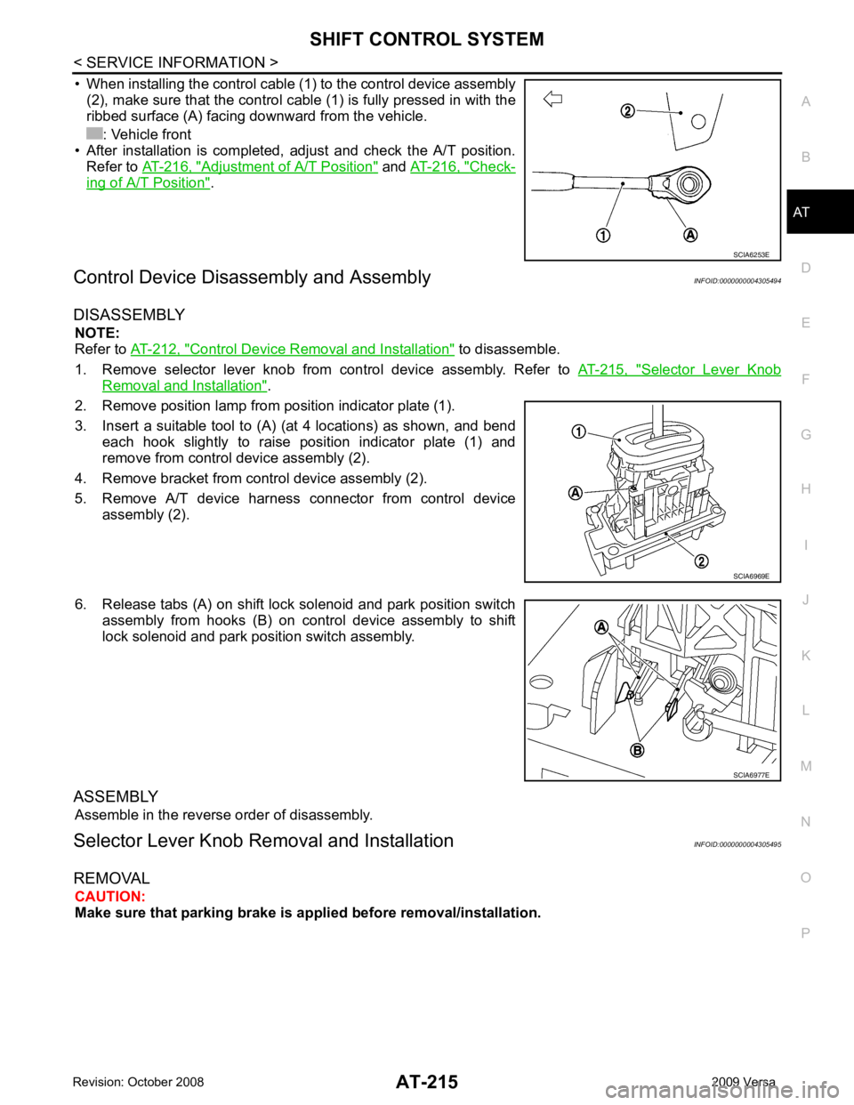
• When installing the control cable (1) to the control device assembly
(2), make sure that the control cable (1) is fully pressed in with the
ribbed surface (A) facing downward from the vehicle.
: Vehicle front
• After installation is completed, adjust and check the A/T position.
Refer to AT-216, " Adjustment of A/T Position " and
AT-216, " Check-
ing of A/T Position " .
Control Device Disassembly and Assembly INFOID:0000000004305494
DISASSEMBLY NOTE:
Refer to AT-212, " Control Device Removal and Installation " to disassemble.
1. Remove selector lever knob from control device assembly. Refer to AT-215, " Selector Lever Knob
Removal and Installation " .
2. Remove position lamp from position indicator plate (1).
3. Insert a suitable tool to (A) (at 4 locations) as shown, and bend each hook slightly to raise position indicator plate (1) and
remove from control device assembly (2).
4. Remove bracket from control device assembly (2).
5. Remove A/T device harness connector from control device assembly (2).
6. Release tabs (A) on shift lock solenoid and park position switch assembly from hooks (B) on control device assembly to shift
lock solenoid and park position switch assembly.
ASSEMBLY Assemble in the reverse order of disassembly.
Selector Lever Knob Re moval and Installation INFOID:0000000004305495
REMOVAL CAUTION:
Make sure that parking brake is a pplied before removal/installation.
Page 266 of 4331
AT
N
O P
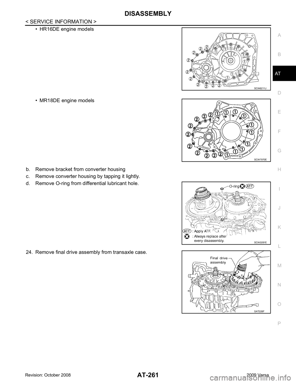
• HR16DE engine models
• MR18DE engine models
b. Remove bracket from converter housing
c. Remove converter housing by tapping it lightly.
d. Remove O-ring from differential lubricant hole.
24. Remove final drive assembly from transaxle case. SCIA7970E
SAT228F
Page 276 of 4331
AT
N
O P
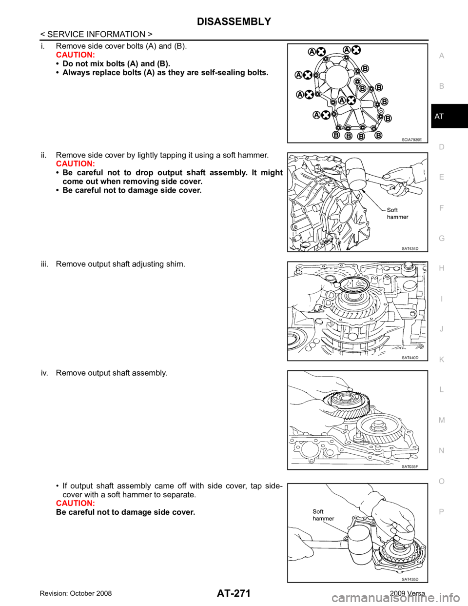
i. Remove side cover bolts (A) and (B).
CAUTION:
• Do not mix bolts (A) and (B).
• Always replace bolts (A) as they are self-sealing bolts.
ii. Remove side cover by lightly tapping it using a soft hammer. CAUTION:
• Be careful not to drop output shaft assembly. It might
come out when removing side cover.
• Be careful not to damage side cover.
iii. Remove output shaft adjusting shim.
iv. Remove output shaft assembly.
• If output shaft assembly came off with side cover, tap side-cover with a soft hammer to separate.
CAUTION:
Be careful not to damage side cover. SAT434D
SAT440D
SAT435D