overheating NISSAN TIIDA 2009 Service Repair Manual
[x] Cancel search | Manufacturer: NISSAN, Model Year: 2009, Model line: TIIDA, Model: NISSAN TIIDA 2009Pages: 4331, PDF Size: 58.04 MB
Page 14 of 4331
AT
N
O P
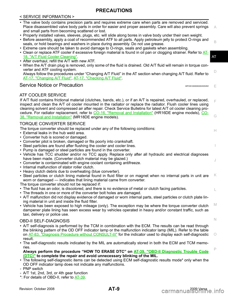
• The valve body contains precision parts and requires extreme care when parts are removed and serviced.
Place disassembled valve body parts in order for easier and proper assembly. Care will also prevent springs
and small parts from becoming scattered or lost.
• Properly installed valves, sleeves, plugs, etc. will slide along bores in valve body under their own weight.
• Before assembly, apply a coat of recommended ATF to all parts. Apply petroleum jelly to protect O-rings and
seals, or hold bearings and washers in pl ace during assembly. Do not use grease.
• Extreme care should be taken to avoid damage to O-rings, seals and gaskets when assembling.
• Clean or replace ATF cooler if excessive foreign material is found in oil pan or clogging strainer. Refer to AT-18, " A/T Fluid Cooler Cleaning " .
• After overhaul, refill the A/T with new ATF.
• When the A/T drain plug is removed, only some of the fluid is drained. Old A/T fluid will remain in torque con- verter and ATF cooling system.
Always follow the procedures under “Changing A/T Fluid” in the AT section when changing A/T fluid. Refer to
AT-17, " Changing A/T Fluid " ,
AT-17, " Checking A/T Fluid " .
Service Notice or Precaution INFOID:0000000004305292
ATF COOLER SERVICE If A/T fluid contains frictional material (clutches, bands, etc.), or if an A/T is repaired, overhauled, or replaced,
inspect and clean the A/T oil cooler mounted in the radiator or replace the radiator. Flush cooler lines using
cleaning solvent and compressed air after repair. Check Serv ice Bulletins for latest A/T oil cooler cleaning pro-
cedure. For radiator replacement, refer to CO-16, " Removal and Installation " (HR16DE engine models),
CO-38, " Removal and Installation " (MR18DE engine models).
TORQUE CONVERTER SERVICE The torque converter should be replaced under any of the following conditions:
• External leaks in the hub weld area.
• Converter hub is scored or damaged.
• Converter pilot is broken, damaged or fits poorly into crankshaft.
• Steel particles are found after flushing the cooler and cooler lines.
• Pump is damaged or steel particles are found in the converter.
• Vehicle has TCC shudder and/or no TCC apply. Replace only after all hydraulic and electrical diagnoses
have been made. (Converter clutch material may be glazed.)
• Converter is contaminated with engi ne coolant containing antifreeze.
• Internal malfunction of stator roller clutch.
• Heavy clutch debris due to overheating (blue converter).
• Steel particles or clutch lining material found in flui d filter or on magnet when no internal parts in unit are
worn or damaged — indicates that lining material came from converter.
The torque converter should not be replaced if:
• The fluid has an odor, is discolored, and there is no evidence of metal or clutch facing particles.
• The threads in one or more of the converter bolt holes are damaged.
• A/T malfunction did not display evidence of damaged or worn internal parts, steel particles or clutch plate lin-
ing material in unit and inside the fluid filter.
• Vehicle has been exposed to high mileage (only). The e xception may be where the torque converter clutch
dampener plate lining has seen excess wear by vehicles operated in heavy and/or constant traffic, such as
taxi, delivery or police use.
OBD-II SELF-DIAGNOSIS • A/T self-diagnosis is performed by the TCM in combination with the ECM. The results can be read through the blinking pattern of the OD OFF indicator lamp or the malfunction indicator lamp (MIL). Refer to the table
on AT-83, " Diagnosis Procedure without CONSULT-III " for the indicator used to display each self-diagnostic
result.
• The self-diagnostic results indicated by the MIL ar e automatically stored in both the ECM and TCM memo-
ries.
Always perform the procedure “HOW TO ERASE DTC” on AT-39, " OBD-II Diagnostic Trouble Code
(DTC) " to complete the repair and avo
id unnecessary blinking of the MIL.
• The following self-diagnostic items can be detected us ing ECM self-diagnostic results mode* only when the
OD OFF indicator lamp does not indicate any malfunctions.
- PNP switch
- A/T 1st, 2nd, 3rd, or 4th gear function
*: For details of OBD-II, refer to AT-39 .
Page 895 of 4331

CO
N
O P
CONTENTS
ENGINE COOLING SYSTEM
HR16DE
PRECAUTION ....... ........................................
3
PRECAUTIONS .............................................. .....3
Precaution for Supplemental Restraint System
(SRS) "AIR BAG" and "SEAT BELT PRE-TEN-
SIONER" ............................................................. ......
3
Precaution Necessary fo r Steering Wheel Rota-
tion After Battery Disconnect ............................... ......
3
Precaution for Liquid Gasket ............................... ......4
PREPARATION .... ........................................5
PREPARATION .............................................. .....5
Special Service Tool ........................................... ......5
Commercial Service Tool .................................... ......5
SYMPTOM DIAGNOSIS ..... ..........................7
OVERHEATING CAUSE ANALYSIS ............. .....7
Troubleshooting Chart ..... ..........................................7
FUNCTION DIAGNOSIS .. .............................9
DESCRIPTION ............................................... .....9
Engine Cooling System ....................................... ......9
Engine Cooling System Schematic ..................... ....10
ON-VEHICLE MAINTENA NCE ....................11
ENGINE COOLANT ....................................... ....11
Inspection ............................................................ ....11
Changing Engine Coolant ................................... ....11
RADIATOR ..................................................... ....14
Checking Radiator Cap ....................................... ....14
Checking Radiator ............................................... ....14
ON-VEHICLE REPAIR .... .............................16
RADIATOR ..................................................... ....16 Component ..........................................................
....16
Removal and Installation ..................................... ....16
COOLING FAN .................................................. 18
Component (Models with A/C) ............................. ....18
Component (Models without A/C) ........................ ....18
Removal and Installation ..................................... ....19
WATER PUMP .................................................. 20
Exploded View ..................................................... ....20
Removal and Installation ..................................... ....20
Inspection ............................................................ ....21
THERMOSTAT .................................................. 22
Exploded View ..................................................... ....22
Removal and Installation ..................................... ....22
Inspection ............................................................ ....23
WATER OUTLET .............................................. 24
Exploded View ..................................................... ....24
Removal and Installation ..................................... ....24
Inspection ............................................................ ....25
DISASSEMBLY AND AS SEMBLY ..............26
COOLING FAN .................................................. 26
Disassembly and Assembly ................................. ....26
SERVICE DATA AND SPECIFICATIONS
(SDS) ............... .............................................
27
SERVICE DATA AND SPECIFICATIONS
(SDS) ................................................................. 27
Periodical Maintenance Specification .................. ....27
Radiator ............................................................... ....27
Thermostat .......................................................... ....27
MR18DE
SERVICE INFORMATION .. .........................28
PRECAUTIONS ................................................. 28
Page 901 of 4331
CO
NP
O
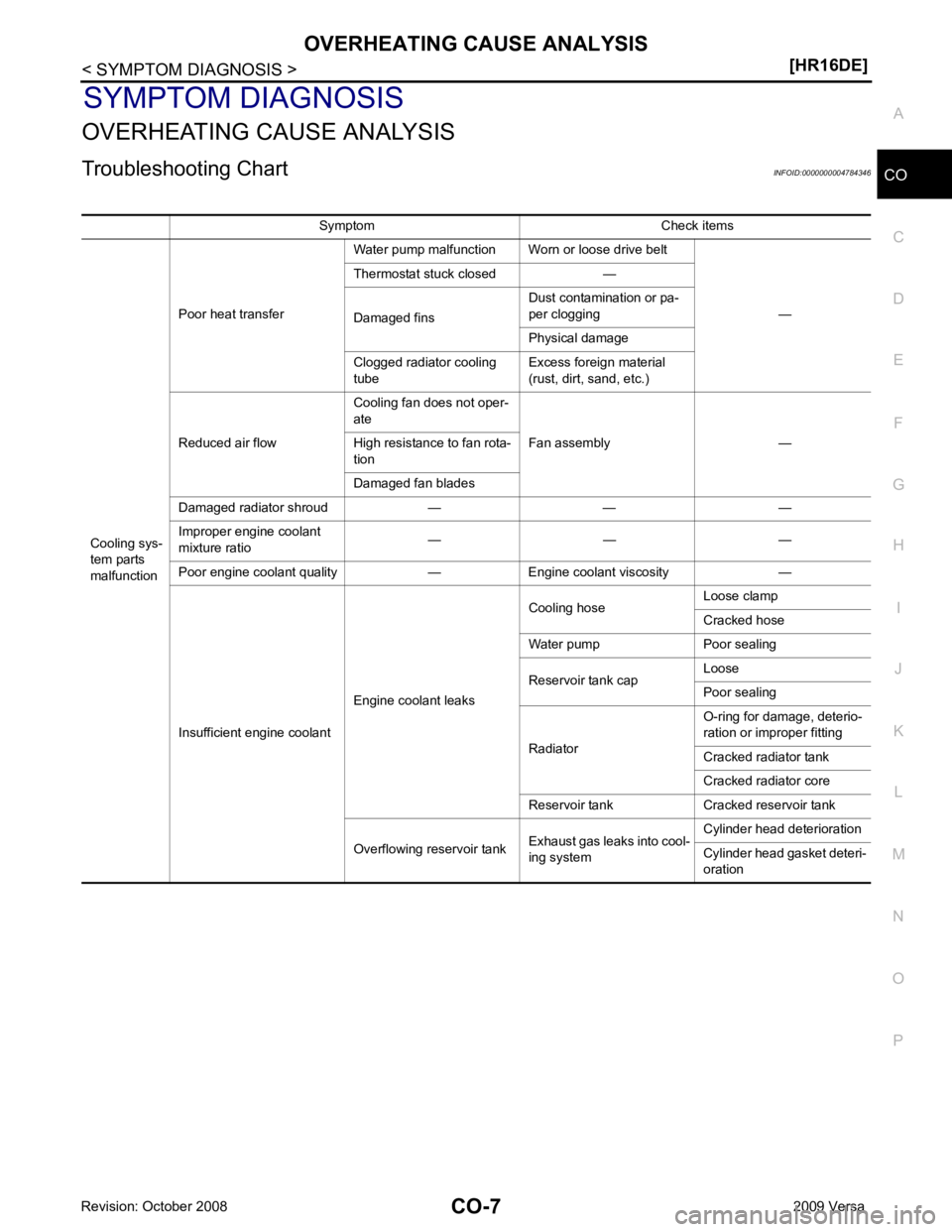
SYMPTOM DIAGNOSIS
OVERHEATING CAUSE ANALYSIS
Troubleshooting Chart INFOID:0000000004784346
Symptom Check items
Cooling sys-
tem parts
malfunction Poor heat transfer
Water pump malfunction Worn or loose drive belt
—
Thermostat stuck closed —
Damaged fins Dust contamination or pa-
per clogging
Physical damage
Clogged radiator cooling
tube Excess foreign material
(rust, dirt, sand, etc.)
Reduced air flow Cooling fan does not oper-
ate
Fan assembly —
High resistance to fan rota-
tion
Damaged fan blades
Damaged radiator shroud — — —
Improper engine coolant
mixture ratio — — —
Poor engine coolant quality — Engine coolant viscosity —
Insufficient engine coolant Engine coolant leaks Cooling hose
Loose clamp
Cracked hose
Water pump Poor sealing
Reservoir tank cap Loose
Poor sealing
Radiator O-ring for damage, deterio-
ration or improper fitting
Cracked radiator tank
Cracked radiator core
Reservoir tank Cracked reservoir tank
Overflowing reservoir tank Exhaust gas leaks into cool-
ing system Cylinder head deterioration
Cylinder head gasket deteri-
oration
Page 1375 of 4331

EC
A
N
O P
DTC P0850 PNP SWITCH ..............................
1401
Component Description ....................................... 1401
CONSULT-III Refe rence Value in Data Monitor
Mode ................................................................... 1401
On Board Diagnosis Logic .................................. 1401
DTC Confirmation Procedure .............................. 1401
Overall Function Check ....................................... 1402
Wiring Diagram ................................................... 1403
Diagnosis Procedure ........................................... 1404
DTC P1148 CLOSED LOOP CONTROL ....... 1407
On Board Diagnosis Logic .................................. 1407
DTC P1217 ENGINE OVER TEMPERATURE 1408
System Description ............................................. 1408
CONSULT-III Refe rence Value in Data Monitor
Mode ................................................................... 1409
On Board Diagnosis Logic .................................. 1409
Overall Function Check ....................................... 1409
Wiring Diagram ................................................... 1411
Diagnosis Procedure ........................................... 1412
Main 13 Causes of Overheating .......................... 1415
Component Inspection ........................................ 1416
DTC P1225 TP SENSOR ............................... 1417
Component Description ....................................... 1417
On Board Diagnosis Logic .................................. 1417
DTC Confirmation Procedure .............................. 1417
Diagnosis Procedure ........................................... 1417
Removal and Installation .....................................1418
DTC P1226 TP SENSOR ............................... 1419
Component Description ....................................... 1419
On Board Diagnosis Logic .................................. 1419
DTC Confirmation Procedure .............................. 1419
Diagnosis Procedure ........................................... 1419
Removal and Installation .....................................1420
DTC P1421 COLD START CONTROL .......... 1421
Description .......................................................... 1421
On Board Diagnosis Logic .................................. 1421
DTC Confirmation Procedure .............................. 1421
Diagnosis Procedure ........................................... 1421
DTC P1564 ASCD STEERING SWITCH ....... 1423
Component Description ....................................... 1423
CONSULT-III Refe rence Value in Data Monitor
Mode ................................................................... 1423
On Board Diagnosis Logic .................................. 1423
DTC Confirmation Procedure .............................. 1424
Wiring Diagram ................................................... 1425
Diagnosis Procedure ........................................... 1426
Component Inspection ........................................ 1428
DTC P1572 ASCD BRAKE SWITCH ............. 1429
Component Description ....................................... 1429
CONSULT-III Refe rence Value in Data Monitor
Mode ................................................................... 1429
On Board Diagnosis Logic .................................. 1429
DTC Confirmation Procedure .............................. 1430Wiring Diagram ....................................................
1431
Diagnosis Procedure ........................................... 1432
Component Inspection ......................................... 1436
DTC P1574 ASCD VEH ICLE SPEED SEN-
SOR ................................................................ 1438
Component Description ....................................... 1438
On Board Diagnosis Logic ................................... 1438
DTC Confirmation Procedure .............................. 1438
Diagnosis Procedure ........................................... 1438
DTC P1715 INPUT SPEED SENSOR (TUR-
BINE REVOLUTION SENSOR) ..................... 1440
Description ........................................................... 1440
CONSULT-III Reference Va lue in Data Monitor
Mode .................................................................... 1440
On Board Diagnosis Logic ................................... 1440
Diagnosis Procedure ........................................... 1440
DTC P1715 INPUT SPEED SENSOR (PRIMA-
RY SPEED SENSOR) ....................................
1441
Description ........................................................... 1441
CONSULT-III Reference Va lue in Data Monitor
Mode .................................................................... 1441
On Board Diagnosis Logic ................................... 1441
DTC Confirmation Procedure .............................. 1441
Diagnosis Procedure ........................................... 1441
DTC P1805 BRAKE SWITCH ........................ 1443
Description ........................................................... 1443
CONSULT-III Reference Va lue in Data Monitor
Mode .................................................................... 1443
On Board Diagnosis Logic ................................... 1443
DTC Confirmation Procedure .............................. 1443
Wiring Diagram .................................................... 1444
Diagnosis Procedure ........................................... 1445
Component Inspection ......................................... 1446
DTC P2100, P2103 THROTTLE CONTROL
MOTOR RELAY ............................................. 1447
Component Description ....................................... 1447
CONSULT-III Reference Va lue in Data Monitor
Mode .................................................................... 1447
On Board Diagnosis Logic ................................... 1447
DTC Confirmation Procedure .............................. 1447
Wiring Diagram .................................................... 1448
Diagnosis Procedure ........................................... 1449
DTC P2101 ELECTRIC THROTTLE CON-
TROL FUNCTION .......................................... 1451
Description ........................................................... 1451
On Board Diagnosis Logic ................................... 1451
DTC Confirmation Procedure .............................. 1451
Wiring Diagram .................................................... 1452
Diagnosis Procedure ........................................... 1453
Component Inspection ......................................... 1456
Removal and Installation ..................................... 1456
DTC P2118 THROTTLE CONTROL MOTOR 1457
Component Description ....................................... 1457
Page 1609 of 4331

EC
NP
O
P0300, P0301, P0302, P0303, P0304 MISFIRE
DTC Logic INFOID:0000000004780152
DTC DETECTION LOGIC When a misfire occurs, engine speed will fluctuate. If the engine speed fluctuates enough to cause the crank-
shaft position (CKP) sensor (POS) signal to vary , ECM can determine that a misfire is occurring.
The misfire detection logic consists of the following two conditions.
1. One Trip Detection Logic (Three Way Catalyst Damage) On the 1st trip , when a misfire condition occurs that can damage the three way catalyst (TWC) due to
overheating, the MIL will blink.
When a misfire condition occurs, the ECM monitors the CKP sensor signal every 200 engine revolutions
for a change.
When the misfire condition decreases to a level t hat will not damage the TWC, the MIL will turn off.
If another misfire condition occurs that can damage the TWC on a second trip, the MIL will blink.
When the misfire condition decreases to a level t hat will not damage the TWC, the MIL will remain on.
If another misfire condition occurs that can damage the TWC, the MIL will begin to blink again.
2. Two Trip Detection Logic (Exhaust quality deterioration) For misfire conditions that will not damage the TWC (but will affect vehicle emissions), the MIL will only
light when the misfire is detected on a second trip. Du ring this condition, the ECM monitors the CKP sen-
sor signal every 1,000 engine revolutions.
A misfire malfunction can be detected on any one cylinder or on multiple cylinders.
DTC CONFIRMATION PROCEDURE YES >> Go to
EC-254, " Diagnosis Procedure " .
NO >> GO TO 3. DTC No. Trouble diagnosis name DTC detecting condition Possible cause
P0300 Multiple cylinder misfire detected Multiple cylinders misfire. • Improper spark plug • Insufficient compression
• Incorrect fuel pressure
• The fuel injector circuit is open or shorted
• Fuel injector
• Intake air leak
• The ignition signal circuit is open or shorted
• Lack of fuel
• Signal plate
• A/F sensor 1
• Incorrect PCV hose connection
P0301 No.1 cylinder misfire detected No. 1 cylinder misfires.
P0302 No. 2 cylinder misfire detected No. 2 cylinder misfires.
P0303 No. 3 cylinder misfire detected No. 3 cylinder misfires.
P0304 No. 4 cylinder misfire detected No. 4 cylinder misfires.
Page 2243 of 4331
EC
NP
O
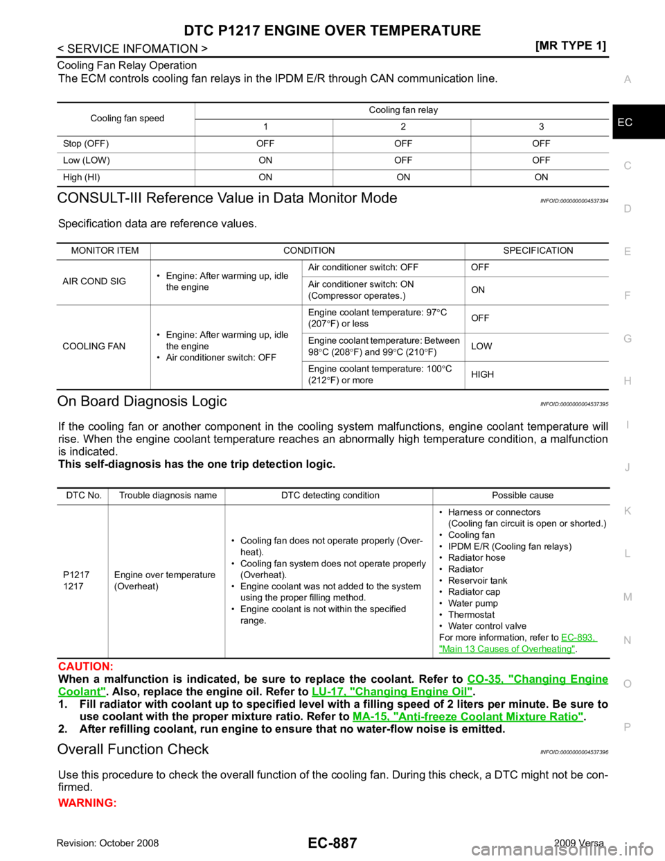
Cooling Fan Relay Operation
The ECM controls cooling fan relays in the IPDM E/R through CAN communication line.
CONSULT-III Reference Val ue in Data Monitor Mode INFOID:0000000004537394
Specification data are reference values.
On Board Diagnosis Logic INFOID:0000000004537395
If the cooling fan or another component in the cooli ng system malfunctions, engine coolant temperature will
rise. When the engine coolant temperature reaches an abnormally high temperature condition, a malfunction
is indicated.
This self-diagnosis has the on e trip detection logic.
CAUTION:
When a malfunction is in dicated, be sure to replace the coolant. Refer to CO-35, " Changing Engine
Coolant " . Also, replace the engine oil. Refer to
LU-17, " Changing Engine Oil " .
1. Fill radiator with coolant up to specified level with a filling speed of 2 liters per minute. Be sure to
use coolant with the proper mixture ratio. Refer to MA-15, " Anti-freeze Coolant Mixture Ratio " .
2. After refilling coolant, run engine to ensure that no water-flow noise is emitted.
Overall Function Check INFOID:0000000004537396
Use this procedure to check the overall function of the cooling fan. During this check, a DTC might not be con-
firmed.
WARNING: Cooling fan speed
Cooling fan relay
1 2 3
Stop (OFF) OFF OFF OFF
Low (LOW) ON OFF OFF
High (HI) ON ON ON MONITOR ITEM CONDITION SPECIFICATION
AIR COND SIG • Engine: After warming up, idle
the engine Air conditioner switch: OFF OFF
Air conditioner switch: ON
(Compressor operates.) ON
COOLING FAN • Engine: After warming up, idle
the engine
• Air conditioner switch: OFF Engine coolant temperature: 97
°C
(207 °F) or less OFF
Engine coolant temperature: Between
98 °C (208 °F) and 99 °C (210 °F) LOW
Engine coolant temperature: 100 °C
(212 °F) or more HIGHDTC No. Trouble diagnosis name DTC detecting condition Possible cause
P1217
1217 Engine over temperature
(Overheat) • Cooling fan does not operate properly (Over-
heat).
• Cooling fan system does not operate properly (Overheat).
• Engine coolant was not added to the system using the proper filling method.
• Engine coolant is not within the specified
range. • Harness or connectors
(Cooling fan circuit is open or shorted.)
• Cooling fan
• IPDM E/R (Cooling fan relays)
• Radiator hose
• Radiator
• Reservoir tank
• Radiator cap
• Water pump
• Thermostat
• Water control valve
For more information, refer to EC-893, " Main 13 Causes of Overheating " .
Page 2247 of 4331
EC
NP
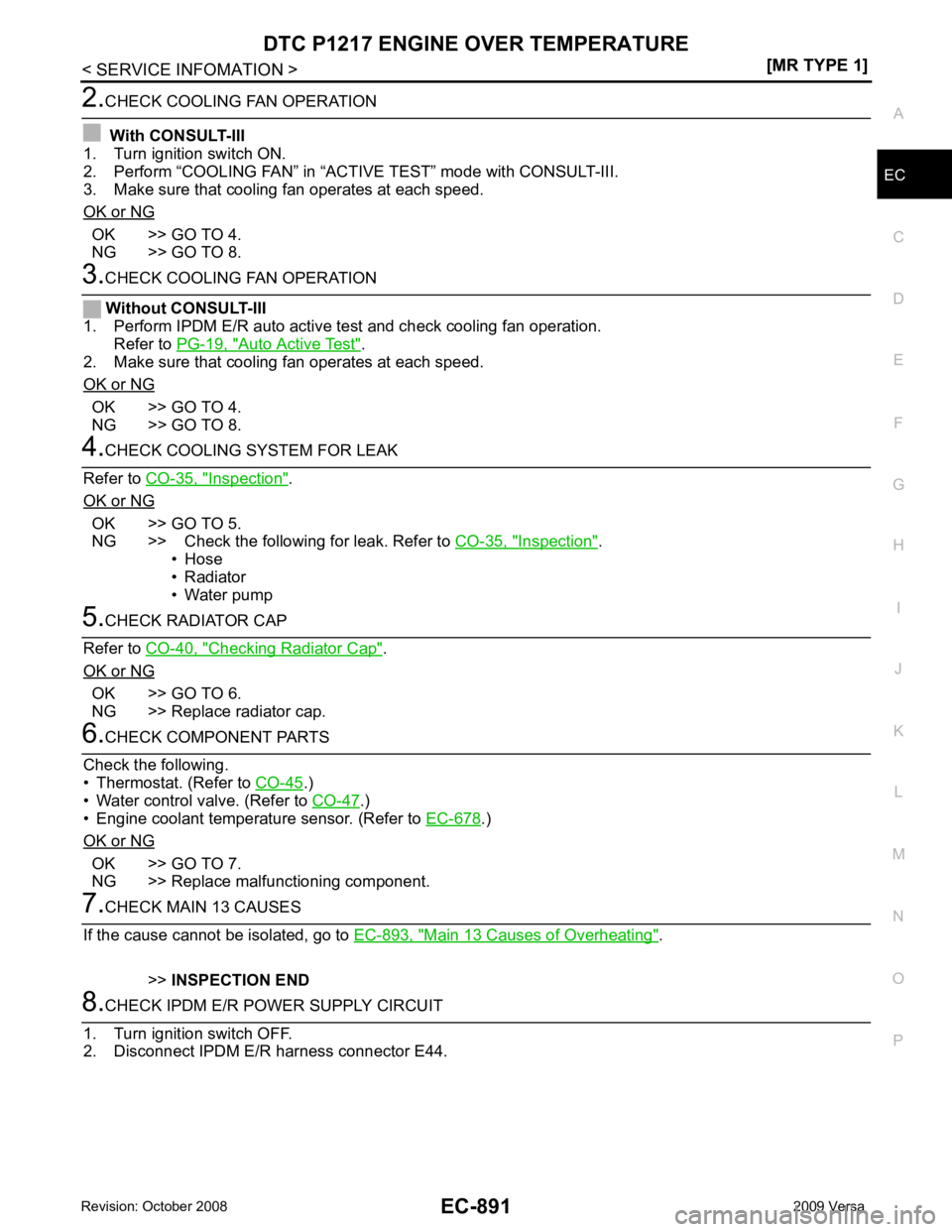
O OK >> GO TO 4.
NG >> GO TO 8. Auto Active Test " .
2. Make sure that cooling fan operates at each speed.
OK or NG OK >> GO TO 4.
NG >> GO TO 8. Inspection " .
OK or NG OK >> GO TO 5.
NG >> Check the following for leak. Refer to CO-35, " Inspection " .
• Hose
• Radiator
• Water pump Checking Radiator Cap " .
OK or NG OK >> GO TO 6.
NG >> Replace radiator cap. .)
• Water control valve. (Refer to CO-47 .)
• Engine coolant temperature sensor. (Refer to EC-678 .)
OK or NG OK >> GO TO 7.
NG >> Replace malfunctioning component. Main 13 Causes of Overheating " .
>> INSPECTION END
Page 2249 of 4331
EC
NP
O
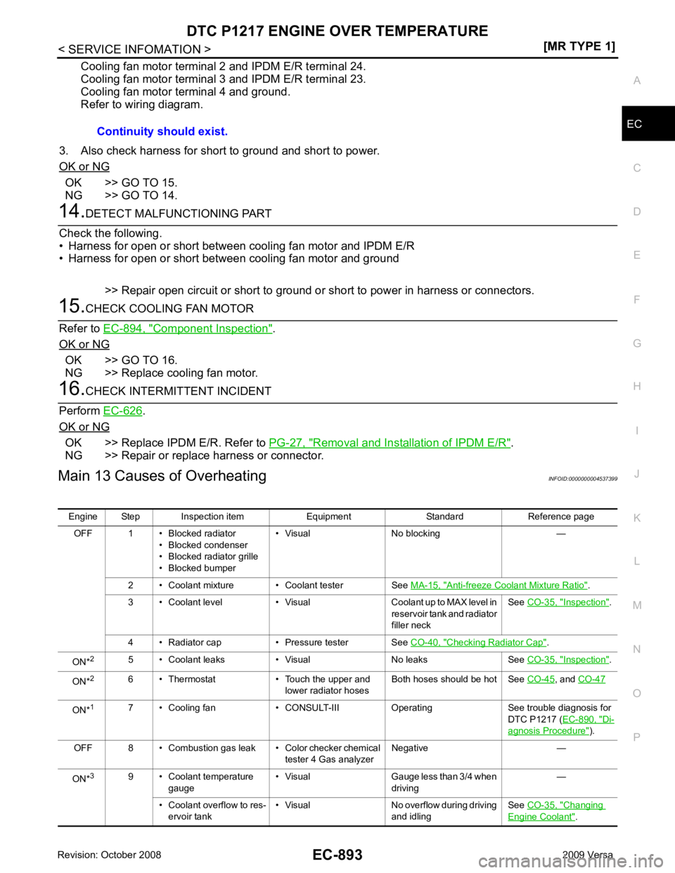
Cooling fan motor terminal 2 and IPDM E/R terminal 24.
Cooling fan motor terminal 3 and IPDM E/R terminal 23.
Cooling fan motor terminal 4 and ground.
Refer to wiring diagram.
3. Also check harness for short to ground and short to power.
OK or NG OK >> GO TO 15.
NG >> GO TO 14. Component Inspection " .
OK or NG OK >> GO TO 16.
NG >> Replace cooling fan motor. .
OK or NG OK >> Replace IPDM E/R. Refer to
PG-27, " Removal and Installation of IPDM E/R " .
NG >> Repair or replace harness or connector.
Main 13 Causes of Overheating INFOID:0000000004537399
Continuity should exist.
Engine Step Inspection item Equipment Standard Reference page OFF 1 • Blocked radiator • Blocked condenser
• Blocked radiator grille
• Blocked bumper • Visual No blocking —
2 • Coolant mixture • Coolant tester See MA-15, " Anti-freeze Coolant Mixture Ratio " .
3 • Coolant level • Visual Coolant up to MAX level in reservoir tank and radiator
filler neck See
CO-35, " Inspection " .
4 • Radiator cap • Pressure tester See CO-40, " Checking Radiator Cap " .
ON* 2
5 • Coolant leaks • Visual No leaks See CO-35, " Inspection " .
ON* 2
6 • Thermostat • Touch the upper and
lower radiator hosesBoth hoses should be hot See
CO-45 , and
CO-47 ON*
1
7 • Cooling fan • CONSULT-III Operating See trouble diagnosis for
DTC P1217 (EC-890, " Di-
agnosis Procedure " ).
OFF 8 • Combustion gas leak • Color checker chemical tester 4 Gas analyzerNegative —
ON* 3
9 • Coolant temperature
gauge • Visual Gauge less than 3/4 when
driving —
• Coolant overflow to res- ervoir tank • Visual No overflow during driving
and idling See
CO-35, " Changing
Engine Coolant " .
Page 2639 of 4331
EC
NP
O
DTC P0300 - P0304 MULTIPLE CYLINDER
MISFIRE, NO. 1 - 4 CYLINDER
MISFIRE
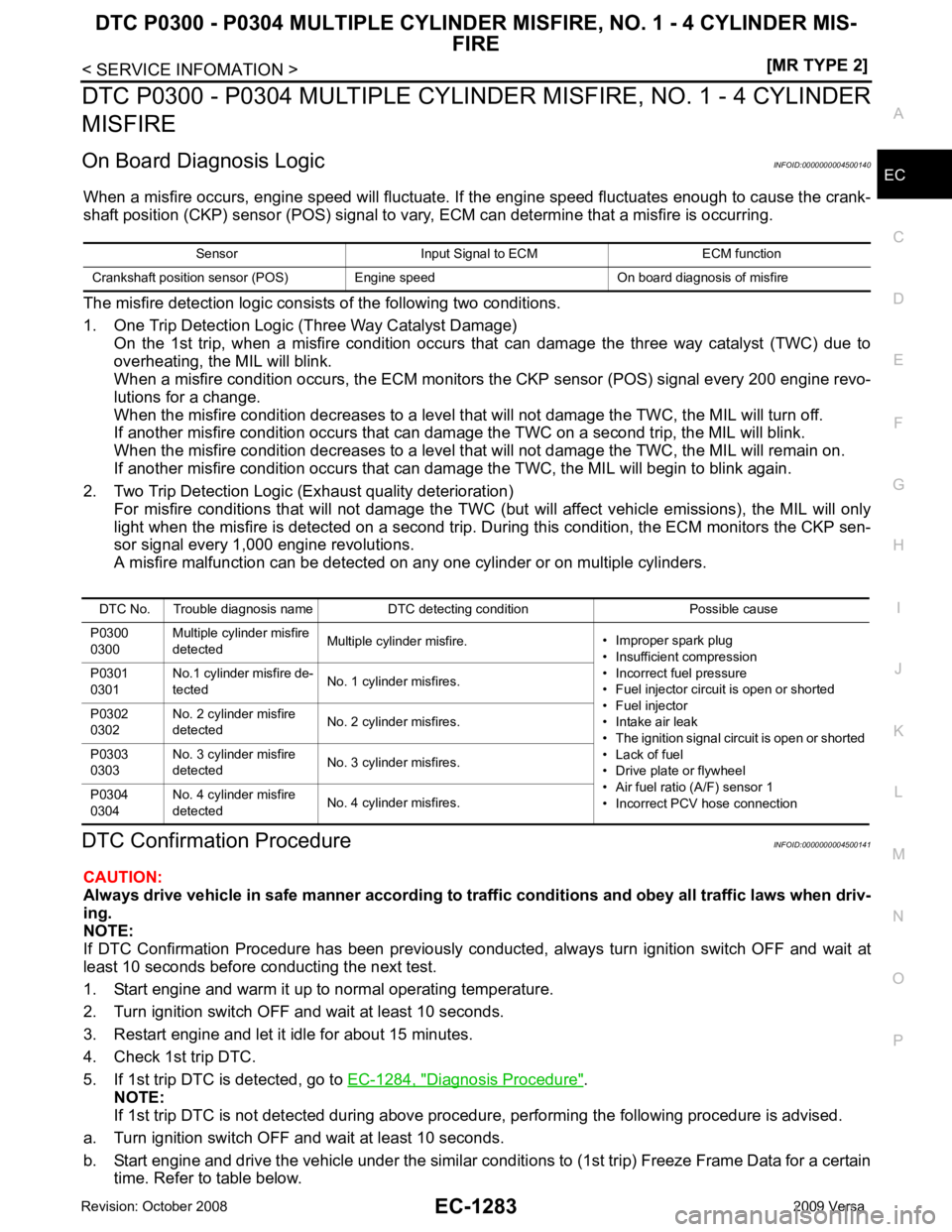
On Board Diagnosis Logic INFOID:0000000004500140
When a misfire occurs, engine speed will fluctuate. If the engine speed fluctuates enough to cause the crank-
shaft position (CKP) sensor (POS) signal to vary , ECM can determine that a misfire is occurring.
The misfire detection logic consists of the following two conditions.
1. One Trip Detection Logic (Three Way Catalyst Damage) On the 1st trip, when a misfire condition occurs that can damage the three way catalyst (TWC) due to
overheating, the MIL will blink.
When a misfire condition occurs, the ECM monitors the CKP sensor (POS) signal every 200 engine revo-
lutions for a change.
When the misfire condition decreases to a level t hat will not damage the TWC, the MIL will turn off.
If another misfire condition occurs that can damage the TWC on a second trip, the MIL will blink.
When the misfire condition decreases to a level t hat will not damage the TWC, the MIL will remain on.
If another misfire condition occurs that can damage the TWC, the MIL will begin to blink again.
2. Two Trip Detection Logic (Exhaust quality deterioration) For misfire conditions that will not damage the TWC (but will affect vehicle emissions), the MIL will only
light when the misfire is detected on a second trip. Du ring this condition, the ECM monitors the CKP sen-
sor signal every 1,000 engine revolutions.
A misfire malfunction can be detected on any one cylinder or on multiple cylinders.
DTC Confirmation Procedure INFOID:0000000004500141
CAUTION:
Always drive vehicle in safe manner according to traf fic conditions and obey all traffic laws when driv-
ing.
NOTE:
If DTC Confirmation Procedure has been previously conduc ted, always turn ignition switch OFF and wait at
least 10 seconds before conducting the next test.
1. Start engine and warm it up to normal operating temperature.
2. Turn ignition switch OFF and wait at least 10 seconds.
3. Restart engine and let it idle for about 15 minutes.
4. Check 1st trip DTC.
5. If 1st trip DTC is detected, go to EC-1284, " Diagnosis Procedure " .
NOTE:
If 1st trip DTC is not detected during above proc edure, performing the following procedure is advised.
a. Turn ignition switch OFF and wait at least 10 seconds.
b. Start engine and drive the vehicle under the similar conditi ons to (1st trip) Freeze Frame Data for a certain
time. Refer to table below. Sensor Input Signal to ECM ECM function
Crankshaft position sensor (POS) Engine speed On board diagnosis of misfire DTC No. Trouble diagnosis name DTC detecting condition Possible cause
P0300
0300 Multiple cylinder misfire
detected Multiple cylinder misfire.
• Improper spark plug
• Insufficient compression
• Incorrect fuel pressure
• Fuel injector circuit is open or shorted
• Fuel injector
• Intake air leak
• The ignition signal circuit is open or shorted
• Lack of fuel
• Drive plate or flywheel
• Air fuel ratio (A/F) sensor 1
• Incorrect PCV hose connection
P0301
0301 No.1 cylinder misfire de-
tected No. 1 cylinder misfires.
P0302
0302 No. 2 cylinder misfire
detected No. 2 cylinder misfires.
P0303
0303 No. 3 cylinder misfire
detected No. 3 cylinder misfires.
P0304
0304 No. 4 cylinder misfire
detected No. 4 cylinder misfires.
Page 2765 of 4331
EC
NP
O
Cooling Fan Relay Operation
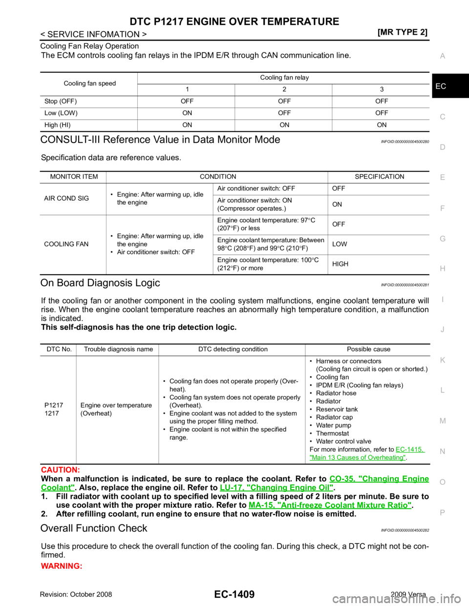
The ECM controls cooling fan relays in the IPDM E/R through CAN communication line.
CONSULT-III Reference Val ue in Data Monitor Mode INFOID:0000000004500280
Specification data are reference values.
On Board Diagnosis Logic INFOID:0000000004500281
If the cooling fan or another component in the cooli ng system malfunctions, engine coolant temperature will
rise. When the engine coolant temperature reaches an abnormally high temperature condition, a malfunction
is indicated.
This self-diagnosis has the on e trip detection logic.
CAUTION:
When a malfunction is in dicated, be sure to replace the coolant. Refer to CO-35, " Changing Engine
Coolant " . Also, replace the engine oil. Refer to
LU-17, " Changing Engine Oil " .
1. Fill radiator with coolant up to specified level with a filling speed of 2 liters per minute. Be sure to
use coolant with the proper mixture ratio. Refer to MA-15, " Anti-freeze Coolant Mixture Ratio " .
2. After refilling coolant, run engine to ensure that no water-flow noise is emitted.
Overall Function Check INFOID:0000000004500282
Use this procedure to check the overall function of the cooling fan. During this check, a DTC might not be con-
firmed.
WARNING: Cooling fan speed
Cooling fan relay
1 2 3
Stop (OFF) OFF OFF OFF
Low (LOW) ON OFF OFF
High (HI) ON ON ON MONITOR ITEM CONDITION SPECIFICATION
AIR COND SIG • Engine: After warming up, idle
the engine Air conditioner switch: OFF OFF
Air conditioner switch: ON
(Compressor operates.) ON
COOLING FAN • Engine: After warming up, idle
the engine
• Air conditioner switch: OFF Engine coolant temperature: 97
°C
(207 °F) or less OFF
Engine coolant temperature: Between
98 °C (208 °F) and 99 °C (210 °F) LOW
Engine coolant temperature: 100 °C
(212 °F) or more HIGHDTC No. Trouble diagnosis name DTC detecting condition Possible cause
P1217
1217 Engine over temperature
(Overheat) • Cooling fan does not operate properly (Over-
heat).
• Cooling fan system does not operate properly (Overheat).
• Engine coolant was not added to the system using the proper filling method.
• Engine coolant is not within the specified
range. • Harness or connectors
(Cooling fan circuit is open or shorted.)
• Cooling fan
• IPDM E/R (Cooling fan relays)
• Radiator hose
• Radiator
• Reservoir tank
• Radiator cap
• Water pump
• Thermostat
• Water control valve
For more information, refer to EC-1415, " Main 13 Causes of Overheating " .