radio antenna NISSAN TIIDA 2009 Service Repair Manual
[x] Cancel search | Manufacturer: NISSAN, Model Year: 2009, Model line: TIIDA, Model: NISSAN TIIDA 2009Pages: 4331, PDF Size: 58.04 MB
Page 385 of 4331

AV
N
O P
CONTENTS
AUDIO, VISUAL, NAVIGATION & TELEPHONE SYS-
TEM
SERVICE INFORMATION .. ..........................2
PRECAUTIONS .............................................. .....2
Precaution for Supplemental Restraint System
(SRS) "AIR BAG" and "SEAT BELT PRE-TEN-
SIONER" ............................................................. ......
2
PREPARATION .............................................. .....3
Commercial Service Tool .................................... ......3
AUDIO ............................................................ .....4
Component Parts Location .................................. ......4
System Description ............................................. ......4
Schematic ........................................................... ......6
Wiring Diagram - AUDIO - ................................... ......8
Audio Unit (Base System) Harness Connector
Terminal Layout .................................................. ....
16
Terminal and Reference Value for Audio Unit
(Base System) ..................................................... ....
16
Audio Unit (Mid Level and Premium System) Har-
ness Connector Terminal Layout ........................ ....
17
Terminal and Reference Value for Audio Unit (Mid
Level and Premium System) ............................... ....
17
Subwoofer Harness Connector Terminal Layout
(Premium Audio System) .................................... ....
20
Terminal and Reference Value for Subwoofer
(Premium Audio System) .................................... ....
20
Satellite Radio Tuner Ha rness Connector Termi-
nal Layout ............................................................ ....
20
Terminal and Reference Value for Satellite Radio
Tuner ................................................................... ....
21
Trouble Diagnosis ............................................... ....21
Noise Inspection .................................................. ....22
Power Supply Circuit Inspection ......................... ....23
Satellite Radio Tuner (Fac tory Installed) Power
and Ground Supply Circuit Inspection ................. ....
24
Satellite Radio Tuner (Fac tory Installed) Commu-
nication Circuit Inspection ................................... ....
25
Satellite Radio Tuner (Fac tory Installed) Left
Channel Audio Signal Circuit Inspection ............. ....
27 Satellite Radio Tuner (Fac
tory Installed) Right
Channel Audio Signal Circuit Inspection ............. ....
27
Steering Switch Check (With Bluetooth) .............. ....28
Sound Is Not Heard from Front Door Speaker
(Base System) ..................................................... ....
30
Sound Is Not Heard from Rear Door Speaker
(Base System) ..................................................... ....
31
Sound Is Not Heard from Front Door Speaker or
Tweeter (Mid Level and Premium System) .............
32
Sound Is Not Heard from Rear Door Speaker (Mid
Level and Premium System) ............................... ....
33
Sound Is Not Heard from Subwoofer (Premium
System) ............................................................... ....
35
Removal and Installation ..................................... ....37
AUDIO ANTENNA ............................................. 42
Location of Antenna ............................................. ....42
Removal and Installation of Roof Antenna ..............42
TELEPHONE ..................................................... 44
Component Parts and Harness Connector Loca-
tion ....................................................................... ....
44
System Description .............................................. ....44
Wiring Diagram - H/PHON - ................................ ....46
Bluetooth Control Unit Harness Connector Termi-
nal Layout ............................................................ ....
48
Terminal and Reference Value for Bluetooth Con-
trol Unit ................................................................ ....
48
Bluetooth Control Unit Se lf-Diagnosis Function ......49
Workflow .............................................................. ....50
Power Supply and Ground Circuit Inspection for
Bluetooth Control Unit .. ...........................................
50
Basic Inspection of Hands-Free Phone ............... ....51
Steering Wheel Audio Co ntrol Switch Does Not
Operate ................................................................ ....
52
Voice Activated Control Fu nction Does Not Oper-
ate ........................................................................ ....
53
Removal and Installation ..................................... ....55
Page 405 of 4331
AUDIO
AV-21
< SERVICE INFORMATION >
C
D E
F
G H
I
J
L
M A
B AV
N
O P
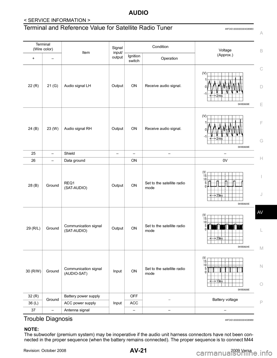
Terminal and Reference Valu
e for Satellite Radio Tuner INFOID:0000000004306965
Trouble Diagnosis INFOID:0000000004306966
NOTE:
The subwoofer (premium system) may be inoperative if the audio unit harness connectors have not been con-
nected in the proper sequence (when the battery remain s connected). The proper sequence is to connect M44
Terminal
(Wire color) ItemSignal
input/
output Condition
Voltage
(Approx.)
+ – Ignition
switch Operation
22 (R) 21 (G) Audio signal LH Output ON Receive audio signal.
24 (B) 23 (W) Audio signal RH Output ON Receive audio signal. 25 – Shield – – – –
26 – Data ground ON 0V
28 (B) Ground REQ1
(SAT-AUDIO) Output ONSet to the satellite radio
mode
29 (R/L) Ground Communication signal
(SAT-AUDIO) Output ONSet to the satellite radio
mode
30 (R/W) Ground Communication signal
(AUDIO-SAT) Input ON
Set to the satellite radio
mode
32 (R) GroundBattery power supply
InputOFF
− Battery voltage
36 (L) ACC power supply ACC
37 – Antenna signal – – – SKIB3609E
SKIB3609E
SKIB3825E
SKIB3824E
SKIB3826E
Page 406 of 4331
35, " Sound Is Not Heard from S
ubwoofer (Premium System) " .
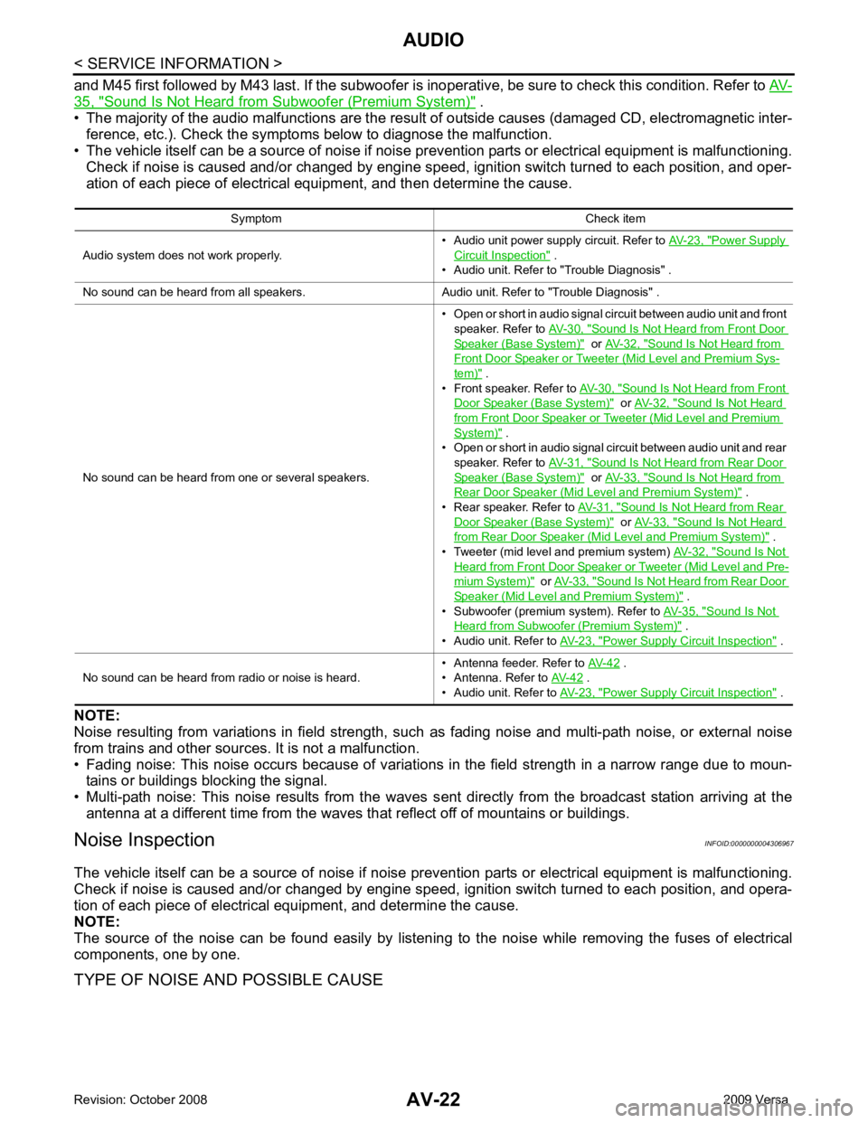
• The majority of the audio malfunctions are the result of outside causes (damaged CD, electromagnetic inter-
ference, etc.). Check the symptom s below to diagnose the malfunction.
• The vehicle itself can be a source of noise if noise prevention parts or electrical equipment is malfunctioning.
Check if noise is caused and/or changed by engine speed, ignition switch turned to each position, and oper-
ation of each piece of electrical equipment, and then determine the cause.
NOTE:
Noise resulting from variations in field strength, such as fading noise and multi-path noise, or external noise
from trains and other sources. It is not a malfunction.
• Fading noise: This noise occurs because of variations in the field strength in a narrow range due to moun- tains or buildings blocking the signal.
• Multi-path noise: This noise results from the waves s ent directly from the broadcast station arriving at the
antenna at a different time from the waves that reflect off of mountains or buildings.
Noise Inspection INFOID:0000000004306967
The vehicle itself can be a source of noise if noise prevention parts or electrical equipment is malfunctioning.
Check if noise is caused and/or changed by engine speed, ignition switch turned to each position, and opera-
tion of each piece of electrical equipment, and determine the cause.
NOTE:
The source of the noise can be found easily by listening to the noise while removing the fuses of electrical
components, one by one.
TYPE OF NOISE AND POSSIBLE CAUSE Symptom Check item
Audio system does not work properly. • Audio unit power supply circuit. Refer to
AV-23, " Power Supply
Circuit Inspection " .
• Audio unit. Refer to "Trouble Diagnosis" .
No sound can be heard from all speakers. Audio unit. Refer to "Trouble Diagnosis" .
No sound can be heard from one or several speakers. • Open or short in audio signal circuit between audio unit and front
speaker. Refer to AV-30, " Sound Is Not Heard from Front Door
Speaker (Base System) " or
AV-32, " Sound Is Not Heard from
Front Door Speaker or Tweeter (Mid Level and Premium Sys-
tem) " .
• Front speaker. Refer to AV-30, " Sound Is Not Heard from Front
Door Speaker (Base System) " or
AV-32, " Sound Is Not Heard
from Front Door Speaker or Tweeter (Mid Level and Premium
System) " .
• Open or short in audio signal circuit between audio unit and rear
speaker. Refer to AV-31, " Sound Is Not Heard from Rear Door
Speaker (Base System) " or
AV-33, " Sound Is Not Heard from
Rear Door Speaker (Mid Level and Premium System) " .
• Rear speaker. Refer to AV-31, " Sound Is Not Heard from Rear
Door Speaker (Base System) " or
AV-33, " Sound Is Not Heard
from Rear Door Speaker (Mid Level and Premium System) " .
• Tweeter (mid level and premium system) AV-32, " Sound Is Not
Heard from Front Door Speaker or Tweeter (Mid Level and Pre-
mium System) " or
AV-33, " Sound Is Not Heard from Rear Door
Speaker (Mid Level and Premium System) " .
• Subwoofer (premium system). Refer to AV-35, " Sound Is Not
Heard from Subwoofer (Premium System) " .
• Audio unit. Refer to AV-23, " Power Supply Circuit Inspection " .
No sound can be heard from radio or noise is heard. • Antenna feeder. Refer to
AV-42 .
• Antenna. Refer to AV-42 .
• Audio unit. Refer to AV-23, " Power Supply Circuit Inspection " .
Page 423 of 4331
AV
N
O P
Sedan
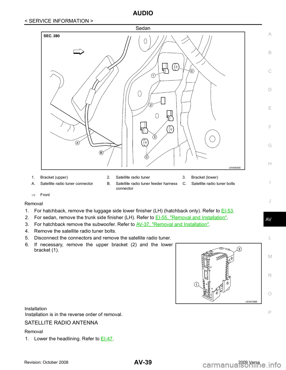
Removal 1. For hatchback, remove the luggage side lower finisher (LH) (hatchback only). Refer to EI-53 .
2. For sedan, remove the trunk side finisher (LH). Refer to EI-55, " Removal and Installation " .
3. For hatchback remove the subwoofer. Refer to AV-37, " Removal and Installation " .
4. Remove the satellite radio tuner bolts.
5. Disconnect the connectors and remove the satellite radio tuner.
6. If necessary, remove the upper bracket (2) and the lower bracket (1).
Installation Installation is in the reverse order of removal.
SATELLITE RADIO ANTENNA
Removal 1. Lower the headlining. Refer to EI-47 .
Page 843 of 4331
BRC
N
O P
Precaution for Brake Control
INFOID:0000000004307252
• During ABS operation, the brake pedal may vibrate lightly and a mechanical noise may be heard. This is normal.
• Just after starting the vehicle, the brake pedal may vibrate or motor operating noises may be heard from
engine compartment. This is normal due to the self check operation.
• Stopping distance may be longer than that of vehicles without ABS when vehicle drives on rough, gravel, or
snow-covered (fresh, deep snow) roads.
• When an error is indicated by ABS or another warning lamp, collect all necessary information from customer
(what symptoms are present under what conditions) and check for simple causes before starting diagnosis.
Besides electrical system inspection, check brake booster operation, brake fluid level, and fluid leaks.
• If incorrect tire sizes or types are installed on the vehicle or brake pads are not Genuine NISSAN parts, stop-
ping distance or steering stability may deteriorate.
• If there is a radio, antenna or related wiring near t he control module, ABS function may have a malfunction
or error.
• If aftermarket parts (car stereo, CD player, etc.) have been installed, check for incidents such as harness pinches, open circuits or improper wiring.
Precaution for CAN System INFOID:0000000004307253
• Do not apply voltage of 7.0V or higher to terminal to be measured.
• Maximum open terminal voltage of tester in use must be less than 7.0V.
• Before checking harnesses, turn ignition switch OFF and disconnect battery negative cable.
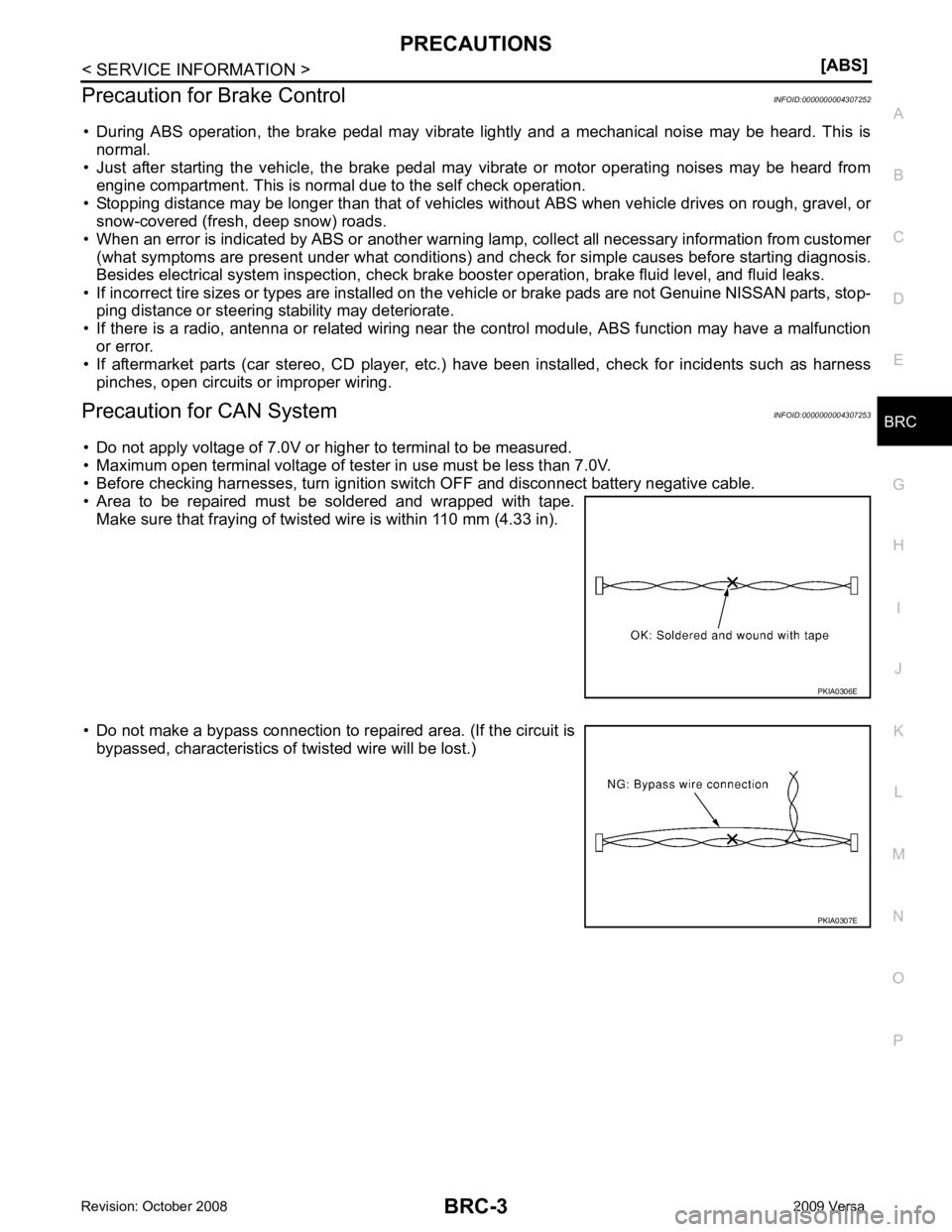
• Area to be repaired must be soldered and wrapped with tape. Make sure that fraying of twisted wire is within 110 mm (4.33 in).
• Do not make a bypass connection to repaired area. (If the circuit is bypassed, characteristics of twisted wire will be lost.)
Page 1851 of 4331
EC
NP
O
•
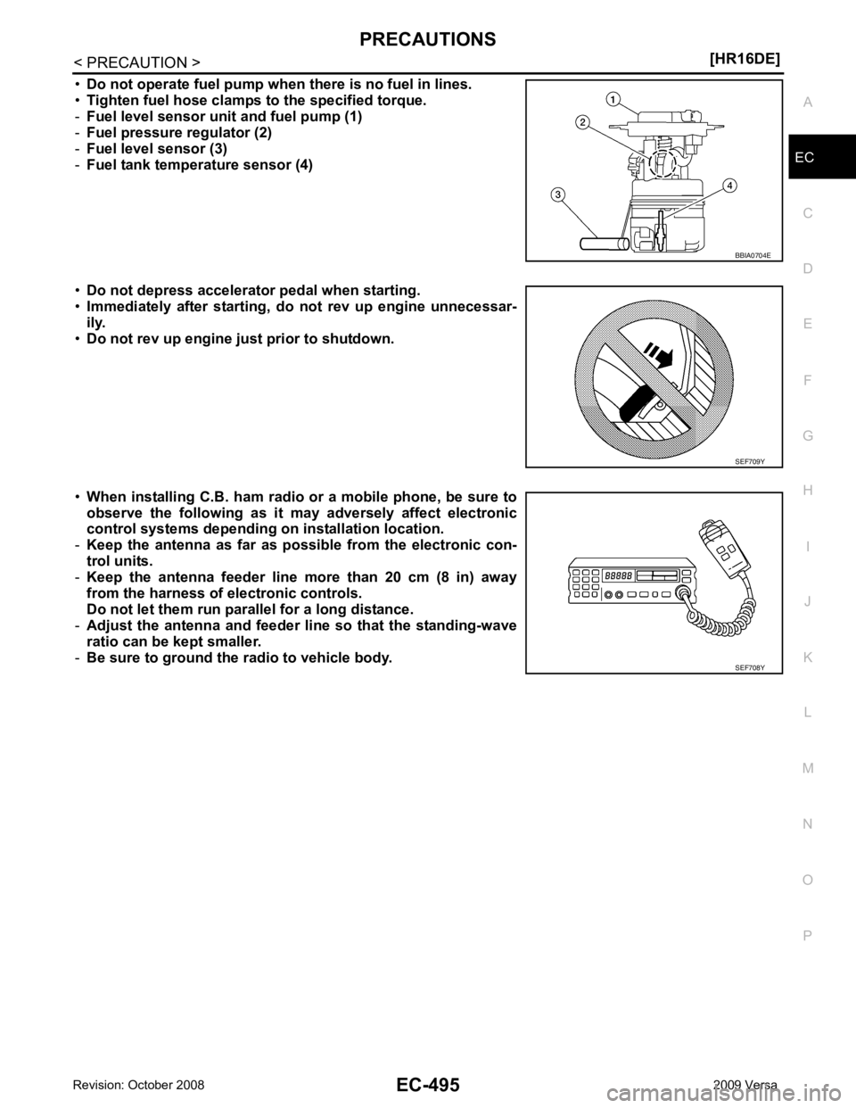
Do not operate fuel pump when there is no fuel in lines.
• Tighten fuel hose clamps to the specified torque.
- Fuel level sensor unit and fuel pump (1)
- Fuel pressure regulator (2)
- Fuel level sensor (3)
- Fuel tank temperature sensor (4)
• Do not depress accelerator pedal when starting.
• Immediately after starting, do not rev up engine unnecessar-
ily.
• Do not rev up engine ju st prior to shutdown.
• When installing C.B. ham radio or a mobile phone, be sure to
observe the following as it may adversely affect electronic
control systems depending on installation location.
- Keep the antenna as far as possible from the electronic con-
trol units.
- Keep the antenna feeder line more than 20 cm (8 in) away
from the harness of electronic controls.
Do not let them run para llel for a long distance.
- Adjust the antenna and feeder line so that the standing-wave
ratio can be kept smaller.
- Be sure to ground the radio to vehicle body.
Page 1871 of 4331
![NISSAN TIIDA 2009 Service Repair Manual PRECAUTIONS
EC-515
< SERVICE INFOMATION >
[MR TYPE 1] C
D E
F
G H
I
J
K L
M A EC
NP
O
•
Do not operate fuel pump when there is no fuel in lines.
• Tighten fuel hose clamps to the specified torqu NISSAN TIIDA 2009 Service Repair Manual PRECAUTIONS
EC-515
< SERVICE INFOMATION >
[MR TYPE 1] C
D E
F
G H
I
J
K L
M A EC
NP
O
•
Do not operate fuel pump when there is no fuel in lines.
• Tighten fuel hose clamps to the specified torqu](/img/5/57398/w960_57398-1870.png)
PRECAUTIONS
EC-515
< SERVICE INFOMATION >
[MR TYPE 1] C
D E
F
G H
I
J
K L
M A EC
NP
O
•
Do not operate fuel pump when there is no fuel in lines.
• Tighten fuel hose clamps to the specified torque.
- Fuel level sensor unit and fuel pump (1)
- Fuel pressure regulator (2)
- Fuel level sensor (3)
- Fuel tank temperature sensor (4)
• Do not depress accelerator pedal when starting.
• Immediately after starting, do not rev up engine unnecessar-
ily.
• Do not rev up engine ju st prior to shutdown.
• When installing C.B. ham radio or a mobile phone, be sure to
observe the following as it may adversely affect electronic
control systems depending on installation location.
- Keep the antenna as far as possible from the electronic con-
trol units.
- Keep the antenna feeder line more than 20 cm (8 in) away
from the harness of electronic controls.
Do not let them run para llel for a long distance.
- Adjust the antenna and feeder line so that the standing-wave
radio can be kept smaller.
- Be sure to ground the radio to vehicle body. BBIA0704E
SEF709Y
SEF708Y
Page 2380 of 4331
![NISSAN TIIDA 2009 Service Repair Manual EC-1024< SERVICE INFOMATION >
[MR TYPE 2]
PRECAUTIONS
• Do not operate fuel pump when there is no fuel in lines.
• Tighten fuel hose clamps to the specified torque.
- Fuel level sensor unit and NISSAN TIIDA 2009 Service Repair Manual EC-1024< SERVICE INFOMATION >
[MR TYPE 2]
PRECAUTIONS
• Do not operate fuel pump when there is no fuel in lines.
• Tighten fuel hose clamps to the specified torque.
- Fuel level sensor unit and](/img/5/57398/w960_57398-2379.png)
EC-1024< SERVICE INFOMATION >
[MR TYPE 2]
PRECAUTIONS
• Do not operate fuel pump when there is no fuel in lines.
• Tighten fuel hose clamps to the specified torque.
- Fuel level sensor unit and fuel pump (1)
- Fuel pressure regulator (2)
- Fuel level sensor (3)
- Fuel tank temperature sensor (4)
• Do not depress accelerator pedal when starting.
• Immediately after starting, do not rev up engine unnecessar-
ily.
• Do not rev up engine just prior to shutdown.
• When installing C.B. ham radio or a mobile phone, be sure to
observe the following as it m ay adversely affect electronic
control systems depending on installation location.
- Keep the antenna as far as possi ble from the electronic con-
trol units.
- Keep the antenna feeder line more than 20 cm (8 in) away
from the harness of electronic controls.
Do not let them run parallel for a long distance.
- Adjust the antenna and feeder line so that the standing-wave
radio can be kept smaller.
- Be sure to ground the radio to vehicle body. BBIA0704E
SEF709Y
SEF708Y