throttle NISSAN TIIDA 2009 Service Repair Manual
[x] Cancel search | Manufacturer: NISSAN, Model Year: 2009, Model line: TIIDA, Model: NISSAN TIIDA 2009Pages: 4331, PDF Size: 58.04 MB
Page 8 of 4331

AT
N
O
P
N
Wiring Diagram - AT -
SSV/B ................................
145
Diagnosis Procedure ........................................... ..146
Component Inspection ........................................ ..147
DTC P1760 OVERRUN CLUTCH SOLENOID
VALVE ............................................................ ..149
Description .......................................................... ..149
CONSULT-III Refe rence Value in Data Monitor
Mode ................................................................... ..
149
On Board Diagnosis Logic .................................. ..149
Possible Cause ................................................... ..149
DTC Confirmation Procedure .............................. ..149
Wiring Diagram - AT - OVRCSV ......................... ..150
Diagnosis Procedure ........................................... ..151
Component Inspection ........................................ ..152
DTC VEHICLE SPEED SENSOR MTR .......... ..154
Description .......................................................... ..154
CONSULT-III Refe rence Value in Data Monitor
Mode ................................................................... ..
154
On Board Diagnosis Logic .................................. ..154
Possible Cause ................................................... ..154
DTC Confirmation Procedure .............................. ..154
Wiring Diagram - AT - VSSMTR ...........................155
Diagnosis Procedure ........................................... ..156
DTC BATT/FLUID TEMP SEN (A/T FLUID
TEMP SENSOR CIRCUIT AND TCM POWER
SOURCE) ....................................................... ..
157
Description .......................................................... ..157
CONSULT-III Refe rence Value in Data Monitor
Mode ................................................................... ..
157
On Board Diagnosis Logic .................................. ..157
Possible Cause ................................................... ..157
DTC Confirmation Procedure .............................. ..157
Wiring Diagram - AT - BA/FTS ............................ ..158
Diagnosis Procedure ........................................... ..159
Component Inspection ........................................ ..161
DTC TURBINE REVOLUTION SENSOR ....... ..163
Description .......................................................... ..163
CONSULT-III Refe rence Value in Data Monitor
Mode ................................................................... ..
163
On Board Diagnosis Logic .................................. ..163
Possible Cause ................................................... ..163
DTC Confirmation Procedure .............................. ..163
Wiring Diagram - AT - PT/SEN ........................... ..164
Diagnosis Procedure ........................................... ..165
CONTROL UNIT (RAM), CONTROL UNIT
(ROM) ............................................................. ..
168
Description .......................................................... ..168
On Board Diagnosis Logic .................................. ..168
Possible Cause ................................................... ..168
DTC Confirmation Procedure .............................. ..168
Diagnosis Procedure ........................................... ..168
MAIN POWER SUPPLY AND GROUND CIR-
CUIT ................................................................ ..169
Wiring Diagram - AT - MAIN ............................... ..169 Diagnosis Procedure ...........................................
..170
PNP, OD SWITCH AND CLOSED THROT-
TLE, WIDE OPEN THROTTLE POSITION
SIGNAL CIRCUI T ............................................ 172
CONSULT-III Reference Va lue in Data Monitor
Mode .................................................................... ..
172
TCM Terminal and Refere nce Value .....................172
Diagnosis Procedure ........................................... ..172
Component Inspection ......................................... ..176
SHIFT POSITION INDICATOR CIRCUIT ........ 177
Description ........................................................... ..177
CONSULT-III Reference Va lue in Data Monitor
Mode .................................................................... ..
177
Diagnosis Procedure ........................................... ..177
TROUBLE DIAGNOSIS FOR SYMPTOMS .... 178
Wiring Diagram - AT - NONDTC ......................... ..178
OD OFF Indicator Lamp Does Not Come On ...... ..181
Engine Cannot Be Started in "P" and "N" Position ..183
In "P" Position, Vehicle Moves Forward or Back-
ward When Pushed ............................................. ..
184
In "N" Position, Vehicle Moves ............................ ..184
Large Shock "N" → "R" Position .......................... ..185
Vehicle Does Not Creep Backward in "R" Position ..186
Vehicle Does Not Creep Forw ard in "D", "2" or "1"
Position ................................................................ ..
187
Vehicle Cannot Be Started from D 1 ..................... ..188
A/T Does Not Shift: D 1→ D 2or Does Not Kick-
down: D 4→ D 2 ..................................................... ..190
A/T Does Not Shift: D 2→ D 3 ................................ ..192
A/T Does Not Shift: D 3→ D 4 ................................ ..193
A/T Does Not Perform Lock-up ........................... ..194
A/T Does Not Hold Lock-up Condition ................. ..195
Lock-up Is Not Released ..................................... ..196
Engine Speed Does Not Return to Idle (Light
Braking D 4→ D 3) ................................................. ..197
A/T Does Not Shift: D 4→ D 3, When OD OFF ...... ..198
A/T Does Not Shift: D 3→ 22, When Selector Lever
"D" → "2" Position ............................................... ..
199
A/T Does Not Shift: 2 2→ 11, When Selector Lever
"2" → "1" Position ................................................ ..
200
Vehicle Does Not Decelerate by Engine Brake ... ..202
TCM Self-Diagnosis Does Not Activate ............... ..205
A/T SHIFT LOCK SYSTEM ............................. 207
Description ........................................................... ..207
Shift Lock System Parts Location ........................ ..207
Wiring Diagram - AT - SHIFT .............................. ..208
Diagnosis Procedure ........................................... ..208
TRANSMISSION CONTROL MODULE .......... 211
Removal and Installation ..................................... ..211
SHIFT CONTROL SYSTEM ............................ 212
Control Device Removal an d Installation ...............212
Control Device Disassembly and Assembly ..........215
Selector Lever Knob Remo val and Installation ......215
Adjustment of A/T Position .................................. ..216
Page 30 of 4331
AT
N
O P
“D
1
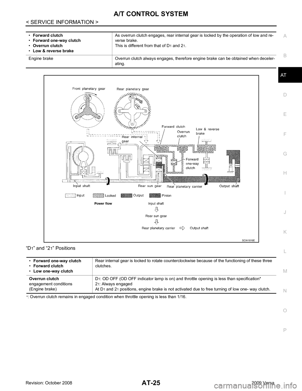
” and “2 1” Positions
* : Overrun clutch remains in engaged condition when throttle opening is less than 1/16.•
Forward clutch
• Forward one-way clutch
• Overrun clutch
• Low & reverse brake As overrun clutch engages, rear internal gear is locked by the operation of low and re-
verse brake.
This is different from that of D 1 and 2 1.
Engine brake Overrun clutch always engages, therefore engine brake can be obtained when deceler- ating.
Page 32 of 4331
AT
N
O P
“D
3
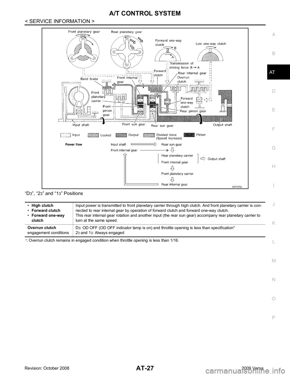
”, “2 3” and “1 3” Positions
* : Overrun clutch remains in engaged condition when throttle opening is less than 1/16.
Page 42 of 4331

AT
N
O P
Control Valve
INFOID:0000000004305307
FUNCTION OF CONTROL VALVES
Centrifugal Cancel Mechanism INFOID:0000000004305308
FUNCTION The centrifugal cancel mechanism is a mechanism to c ancel the centrifugal hydraulic pressure instead of the
conventional check balls. It cancels the centrifugal hy draulic pressure which is generated as high clutch drum
rotates, and it allows for preventing high clutch from dragging and for providing stable high clutch piston press-
ing force in all revolution speeds.
STRUCTURE/OPERATION Valve name Function
Pressure regulator valve, plug and sleeve
plug Regulates oil discharged from the oil pump to provide optimum line pressure for all driving
conditions.
Pressure modifier valve and sleeve Used as a signal supplementary valve to the pressure regulator valve. Regulates pres- sure-modifier pressure (signal pressure) which controls optimum line pressure for all driv-
ing conditions.
Pilot valve Regulates line pressure to maintain a constant pilot pressure level which controls lock-up mechanism, overrun clutch, shift timing.
Accumulator control valve Regulates accumulator back-pressure to pressure suited to driving conditions.
Manual valve Directs line pressure to oil circuits corresponding to select positions. Hydraulic pressure drains when the shift lever is in Neutral.
Shift valve A Simultaneously switches three oil circuits using output pressure of shift solenoid valve A to meet driving conditions (vehicle speed, throttle opening, etc.).
Provides automatic downshifting and upshifting (1st → 2nd → 3rd → 4th gears/4th → 3rd
→ 2nd → 1st gears) in combination with shift valve B.
Shift valve B Simultaneously switches two oil circuits using output pressure of shift solenoid valve B in relation to driving conditions (vehicle speed, throttle opening, etc.).
Provides automatic downshifting and upshifting (1st → 2nd → 3rd → 4th gears/4th → 3rd
→ 2nd → 1st gears) in combination with shift valve A.
Overrun clutch control valve Switches hydraulic circuits to prevent engagement of the overrun clutch simultaneously with application of the brake band in D4. (Interlocking occurs if the overrun clutch engages
during D 4.)
1st reducing valve Reduces low & reverse brake pressure to dampen engine-brake shock when downshift- ing from the 1st position 12 to 1 1.
Overrun clutch reducing valve Reduces oil pressure directed to the overrun clutch and prevents engine-brake shock. In the 1st and 2nd positions, line pressure acts on the overrun clutch reducing valve to
increase the pressure-regulating point, with resultant engine brake capability.
Torque converter relief valve Prevents an excessive rise in torque converter pressure.
Torque converter clutch control valve, plug
and sleeve Activates or inactivates the lock-up function.
Also provides smooth lock-up through transient application and release of the lock-up
system.
1-2 accumulator valve and piston Lessens the shock find when the 2nd gear band servo contracts, and provides smooth shifting.
3-2 timing valve Switches the pace that oil pressure is released depending on vehicle speed; maximizes the high clutch release timing, and allows for soft downshifting.
Shuttle valve Determines if the overrun clutch solenoid valve should control the 3-2 timing valve or the overrun clutch control valve and switches between the two.
Cooler check valve At low speeds and with a small load when a little heat is generated, saves the volume of cooler flow, and stores the oil pressure for lock-up.
Page 47 of 4331

.
Fail-Safe INFOID:0000000004305315
The TCM has an electronic Fail-safe mode. This allows t he vehicle to be driven even if a major electrical input/
output device circuit is damaged.
Under Fail-Safe, the vehicle always runs in third gear, even with a shift lever position of “1”, “2” or “D”. The cus-
tomer may complain of sluggish or poor acceleration.
Always follow the “ AT-43, " How to Perform Trouble Diagnosis for Quick and Accurate Repair " ”.
The SELF-DIAGNOSIS results will be as follows:
• The first SELF-DIAGNOSIS will indicate damage to t he vehicle speed sensor or the revolution sensor.
• During the next SELF-DIAGNOSIS, performed after checking the sensor, no damages will be indicated.
FAIL-SAFE FUNCTION
The following fail-safe functions allow vehicles to be driven even when sensor, switch or solenoid malfunction
occurs.
Vehicle Speed Sensor·A/T (Revolution Sensor)
Vehicle speed sensor·MTR signal is input from combination meter.
Accelerator Pedal Position Signal and Throttle Position Signal
TCM controls the throttle opening angle to a predetermi ned fixed position to enable driving if a malfunctioning
signal is input to TCM.
PNP Switch
When the multiple PNP switch signals are input to TCM, the priority of selector lever position becomes “D”,
“N”, “R”, “2” and “1” in order by internal TCM determination.
The use of 4th gear is inhibited unt il normal operation resumes. Because t he hydraulic circuit of the control
valve is switched by manual valve according to the sele ctor lever position, however, actual operating condition
of vehicle becomes as follows.
Shift Solenoid Valve A and B
If non-standard solenoid signal is sent to TCM, use of certain gears is limited. Refer to chart shown below.
Priority Detected items
1 CAN communication line
2 Except above Actual lever position PNP switch input signal Running status
“P” “P” position and other position signals P
“R” “R” position and other position signals R
“N” “N” position and other position signals N
“D” “D” position and other position signals D 1
⇔ D2 ⇔ D3 ⇔ D4
“2” “2” position and other position signals (Except “1” position) 2
1 ⇔ 22 ⇔ 23
“2” position and “1” position signals 2 1 ⇔ 22
“1” “1” position and other position signals (Except “2” position) 1
1
⇔ 12 ⇔ 13
“1” position and “2” position signals 1 1 ⇔ 12
Page 57 of 4331
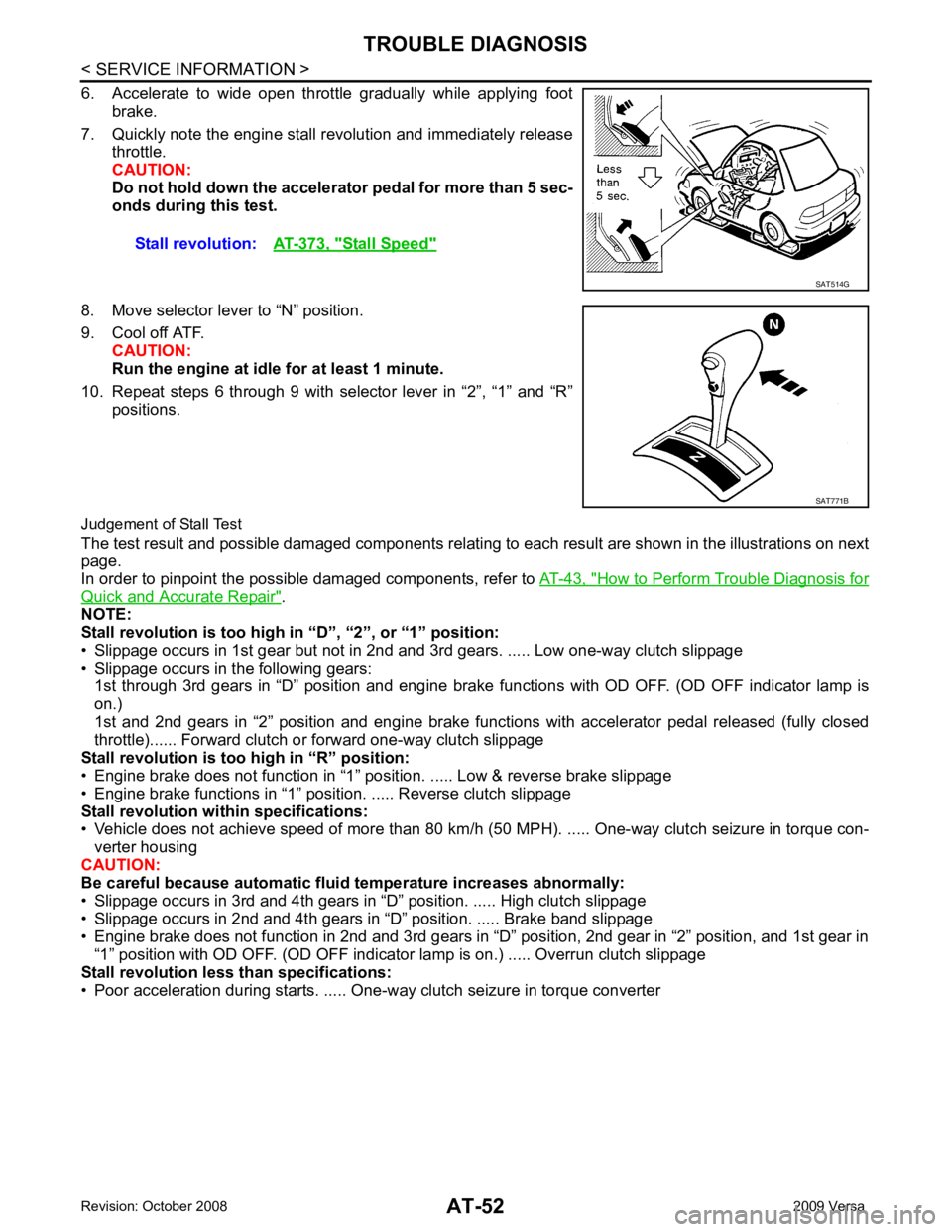
How to Perform Trouble Diagnosis for
Quick and Accurate Repair " .
NOTE:
Stall revolution is too high in “D”, “2”, or “1” position:
• Slippage occurs in 1st gear but not in 2nd and 3rd gears. ..... Low one-way clutch slippage
• Slippage occurs in the following gears:
1st through 3rd gears in “D” position and engine brake f unctions with OD OFF. (OD OFF indicator lamp is
on.)
1st and 2nd gears in “2” position and engine brake functions with accelerator pedal released (fully closed
throttle)...... Forwar d clutch or forward one-way clutch slippage
Stall revolution is too high in “R” position:
• Engine brake does not function in “1” posit ion. ..... Low & reverse brake slippage
• Engine brake functions in “1” position. ..... Reverse clutch slippage
Stall revolution with in specifications:
• Vehicle does not achieve speed of more than 80 km/h ( 50 MPH). ..... One-way clutch seizure in torque con-
verter housing
CAUTION:
Be careful because automatic flui d temperature increases abnormally:
• Slippage occurs in 3rd and 4th gears in “D” position. ..... High clutch slippage
• Slippage occurs in 2nd and 4th gears in “D” position. ..... Brake band slippage
• Engine brake does not function in 2nd and 3rd gears in “D” position, 2nd gear in “2” position, and 1st gear in “1” position with OD OFF. (OD OFF indicator lamp is on.) ..... Overrun clutch slippage
Stall revolution less than specifications:
• Poor acceleration during starts. ..... One-way clutch seizure in torque converter Stall revolution:
AT-373, " Stall Speed "
SAT771B
Page 65 of 4331

CONSULT-III Funct
ion (TRANSMISSION) " .
Does A/T shift from D YES >> GO TO 4.
NO >> • Mark the box on the “Diagnostic Worksheet Chart”.
• Go to AT-192, " A/T Does Not Shift: D .
• Continue “Road Test”. Vehicle Speed at Which Gear Shifting Occurs " .
Read gear position, throttl e opening and vehicle speed.
Refer to AT-79, " CONSULT-III Funct
ion (TRANSMISSION) " .
Does A/T shift from D YES >> GO TO 5.
NO >> • Mark the box on the “Diagnostic Worksheet Chart”. • Go to AT-193, " A/T Does Not Shift: D .
• Continue “Road Test”. Vehicle Speed at Which Lock-up Occurs/Releases " .
Read vehicle speed, throttle opening when lock-up duty
becomes 94%. Refer to AT-79, " CONSULT-III Fu
nction (TRANS-MISSION) " .
Does A/T perform lock-up at the specified speed?YES >> GO TO 6.
NO >> • Mark the box on the “Diagnostic Worksheet Chart”.
• Go to AT-194, " A/T Does Not Perform Lock-up " .
• Continue “Road Test”. CONSULT-III Function (TRANSMISSION) " .
Does A/T hold lock-up condition for more than 30 seconds? YES >> GO TO 7.
NO >> • Mark the box on the “Diagnostic Worksheet Chart”. • Go to AT-195, " A/T Does Not Hold Lock-up Condition " .
• Continue “Road Test”. CONSULT-III Function (TRANSMISSION) " .
Is lock-up released when accelerator pedal is released? YES >> GO TO 8.
NO >> • Mark the box on the “Diagnostic Worksheet Chart”. • Go to AT-196, " Lock-up Is Not Released " . SCIA7190E
Page 66 of 4331
TROUBLE DIAGNOSIS
AT-61
< SERVICE INFORMATION >
D
E
F
G H
I
J
K L
M A
B AT
N
O P
• Continue “Road Test”. 8.
CHECK SHIFT-DOWN (D 4 TO D 3 )
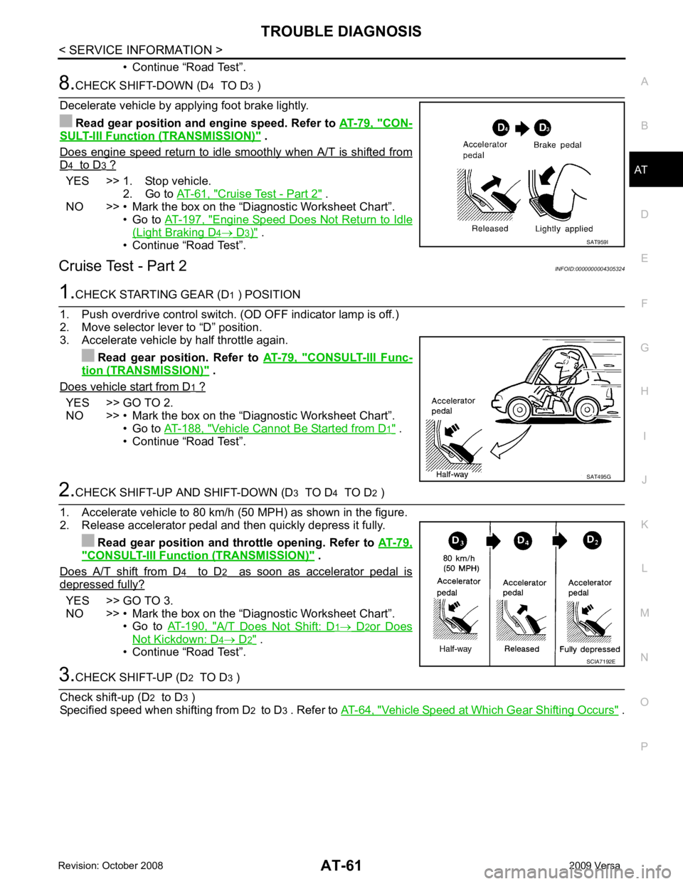
Decelerate vehicle by applying foot brake lightly. Read gear position and engine speed. Refer to AT-79, " CON-
SULT-III Functi
on (TRANSMISSION) " .
Does engine speed return to idle smoothly when A/T is shifted from D 4 to D 3 ?
YES >> 1. Stop vehicle.
2. Go to AT-61, " Cruise Test - Part 2 " .
NO >> • Mark the box on the “D iagnostic Worksheet Chart”.
• Go to AT-197, " Engine Speed Does Not Return to Idle
(Light Braking D 4 → D 3 ) " .
• Continue “Road Test”.
Cruise Test - Part 2 INFOID:00000000043053241.
CHECK STARTING GEAR (D 1 ) POSITION
1. Push overdrive control switch. (OD OFF indicator lamp is off.)
2. Move selector lever to “D” position.
3. Accelerate vehicle by half throttle again.
Read gear position. Refer to AT-79, " CONSULT-III Func-
tion (TRANSMISSION) " .
Does vehicle start from D 1 ?
YES >> GO TO 2.
NO >> • Mark the box on the “D iagnostic Worksheet Chart”.
• Go to AT-188, " Vehicle Cannot Be Started from D 1 " .
• Continue “Road Test”. 2.
CHECK SHIFT-UP AND SHIFT-DOWN (D 3 TO D 4 TO D 2 )
1. Accelerate vehicle to 80 km/h (50 MPH) as shown in the figure.
2. Release accelerator pedal and then quickly depress it fully.
Read gear position and th rottle opening. Refer to AT-79," CONSULT-III Function (TRANSMISSION) " .
Does A/T shift from D 4 to D 2 as soon as accelerator pedal is
depressed fully?
YES >> GO TO 3.
NO >> • Mark the box on the “D iagnostic Worksheet Chart”.
• Go to AT-190, " A/T Does Not Shift: D 1 → D 2 or Does
Not Kickdown: D 4 → D 2 " .
• Continue “Road Test”. 3.
CHECK SHIFT-UP (D 2 TO D 3 )
Check shift-up (D 2 to D 3 )
Specified speed when shifting from D 2 to D 3 . Refer to AT-64, " Vehicle Speed at Which Gear Shifting Occurs " .SAT959I
SAT495G
SCIA7192E
Page 69 of 4331

CONSULT-III Function
(TRANSMISSION) " .
Does A/T shift from 2 YES >> GO TO 6.
NO >> • Mark the box on the “Diagnostic Worksheet Chart”.
• Go to AT-200, " A/T Does Not Shift: 2
Selector Lever "2" " .
• Continue “Road Test”. YES >> 1. Stop vehicle.
2. Perform self-diagnosis. Refer to AT-79, " CONSULT-
III Function (TRANSMISSION) " ,
AT-83, " Diagnosis
Procedure without CONSULT-III " .
NO >> • Mark the box on the “Diagnostic Worksheet Chart”. • Go to AT-202, " Vehicle Does Not Decelerate by
Engine Brake " .
• Stop “Road Test”.
Vehicle Speed at Which Gear Shifting Occurs INFOID:0000000004305326
MR16DE engine models
MR18DE engine models
• At half throttle, the accelerator opening is 4/8 of the full opening.
Vehicle Speed at Which Lock-up Occurs/Releases INFOID:0000000004305327
MR16DE engine models
MR18DE engine models SAT778B
Throttle position Selector lever position
Vehicle speed km/h (MPH)
Lock-up ON Lock-up OFF
2.0/8 “D” position 73 - 81 (46
- 50) 49 - 57 (31 - 35)
“D” position (OD OFF) 86 - 94 (53 - 58) 82 - 90 (51 - 55)
Throttle position Selector lever position Vehicle speed km/h (MPH)
Lock-up ON Lock-up OFF
2.0/8 “D” position 86 - 94 (53
- 58) 59 - 67 (37 - 42)
“D” position (OD OFF) 86 - 94 (53 - 58) 83 - 91 (52 - 57)
Page 84 of 4331
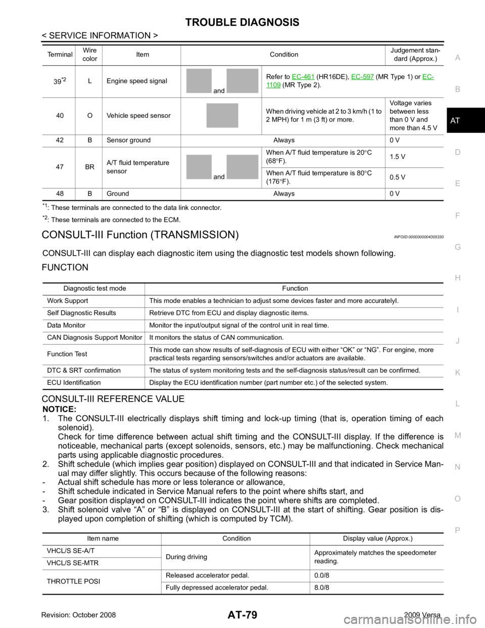
AT
N
O P
*1
: These terminals are connected to the data link connector.
*2 : These terminals are connected to the ECM.
CONSULT-III Function (TRANSMISSION) INFOID:0000000004305330
CONSULT-III can display each diagnostic item using the diagnostic test models shown following.
FUNCTION
CONSULT-III REFERENCE VALUE NOTICE:
1. The CONSULT-III electrically displays shift timi ng and lock-up timing (that is, operation timing of each
solenoid).
Check for time difference between actual shift timi ng and the CONSULT-III display. If the difference is
noticeable, mechanical parts (except solenoids, sens ors, etc.) may be malfunctioning. Check mechanical
parts using applicable diagnostic procedures.
2. Shift schedule (which implies gear position) display ed on CONSULT-III and that indicated in Service Man-
ual may differ slightly. This occurs because of the following reasons:
- Actual shift schedule has more or less tolerance or allowance,
- Shift schedule indicated in Service Manual re fers to the point where shifts start, and
- Gear position displayed on CONSULT-III indicates the point where shifts are completed.
3. Shift solenoid valve “A” or “B” is displayed on CONSUL T-III at the start of shifting. Gear position is dis-
played upon completion of shifting (which is computed by TCM).
39
*2
L Engine speed signal
and Refer to
EC-461 (HR16DE),
EC-597 (MR Type 1) or
EC- 1109 (MR Type 2).
40 O Vehicle speed sensor When driving vehicle at 2 to 3 km/h (1 to
2 MPH) for 1 m (3 ft) or more. Voltage varies
between less
than 0 V and
more than 4.5 V
42 B Sensor ground Always 0 V
47 BR A/T fluid temperature
sensor and When A/T fluid temperature is 20
°C
(68 °F). 1.5 V
When A/T fluid temperature is 80 °C
(176 °F). 0.5 V
48 B Ground Always 0 V
Terminal
Wire
color Item Condition Judgement stan-
dard (Approx.) Diagnostic test mode Function
Work Support This mode enables a technician to adjust some devices faster and more accuratelyI.
Self Diagnostic Results Retrieve DTC from ECU and display diagnostic items.
Data Monitor Monitor the input/output signal of the control unit in real time.
CAN Diagnosis Support Monitor It monitors the status of CAN communication.
Function Test This mode can show results of self-diagnosis of ECU with either “OK” or “NG”. For engine, more
practical tests regarding sensors/switches and/or actuators are available.
DTC & SRT confirmation The status of system monitoring tests and the self-diagnosis status/result can be confirmed.
ECU Identification Display the ECU identification number (part number etc.) of the selected system. Item name Condition Display value (Approx.)
VHCL/S SE-A/T During driving Approximately matches the speedometer
reading.
VHCL/S SE-MTR
THROTTLE POSI Released accelerator pedal. 0.0/8
Fully depressed accelerator pedal. 8.0/8