Body front NISSAN TIIDA 2010 Service User Guide
[x] Cancel search | Manufacturer: NISSAN, Model Year: 2010, Model line: TIIDA, Model: NISSAN TIIDA 2010Pages: 3745, PDF Size: 73.67 MB
Page 505 of 3745
BCS-16
< SERVICE INFORMATION >
BCM (BODY CONTROL MODULE)
1: With Intelligent Key
2: Without Intelligent Key
3: Hatchback without Intelligent Key
4: Sedan without Intelligent Key
5: Hatchback
6: Sedan
7: With power door locks
8: With power windows
BCM Power Supply and Ground Circuit InspectionINFOID:0000000005395108
1.CHECK FUSES AND FUSIBLE LINK
• Check 40A fusible link (letter g , located in the fuse and fusible link box).
• Check 10A fuses [No. 6, 8 and 20, lo cated in the fuse block (J/B)].
OK or NG
OK >> GO TO 2.
NG >> If fuse is blown, be sure to eliminate cause of malfunction before installing new fuse. Refer to PG-
4, "Schematic" .
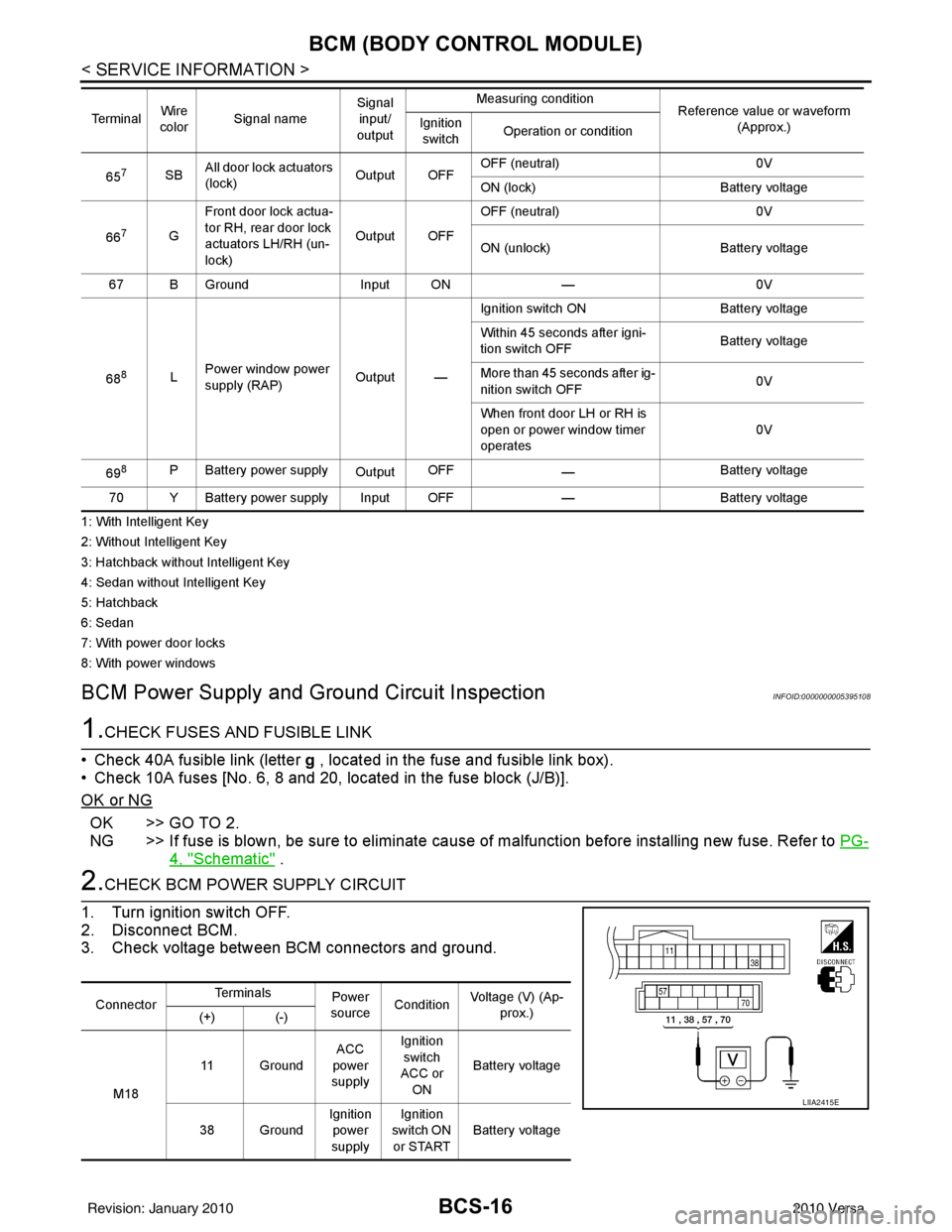
2.CHECK BCM POWER SUPPLY CIRCUIT
1. Turn ignition switch OFF.
2. Disconnect BCM.
3. Check voltage between BCM connectors and ground.
657SB All door lock actuators
(lock) Output OFFOFF (neutral)
0V
ON (lock) Battery voltage
66
7G Front door lock actua-
tor RH, rear door lock
actuators LH/RH (un-
lock) Output OFFOFF (neutral)
0V
ON (unlock) Battery voltage
67 B Ground Input ON—0V
68
8L Power window power
supply (RAP)
Output —Ignition switch ON
Battery voltage
Within 45 seconds after igni-
tion switch OFF Battery voltage
More than 45 seconds after ig-
nition switch OFF 0V
When front door LH or RH is
open or power window timer
operates 0V
69
8P Battery power supply OutputOFF
— Battery voltage
70 Y Battery power supply Input OFF —Battery voltage
Te r m i n a l
Wire
color Signal name Signal
input/
output Measuring condition
Reference value or waveform
(Approx.)
Ignition
switch Operation or condition
Connector Te r m i n a l s
Power
source Condition Voltage (V) (Ap-
prox.)
(+) (-)
M18 11 Ground
ACC
power
supply Ignition
switch
ACC or
ON Battery voltage
38 Ground Ignition
power
supply Ignition
switch ON or START Battery voltage
LIIA2415E
Revision: January 20102010 Versa
Page 510 of 3745

BL-1
BODY
C
DE
F
G H
J
K L
M
SECTION BL
A
B
BL
N
O P
CONTENTS
BODY, LOCK & SECURITY SYSTEM
SERVICE INFORMATION .. ..........................4
PRECAUTIONS .............................................. .....4
Precaution for Supplemental Restraint System
(SRS) "AIR BAG" and "SEAT BELT PRE-TEN-
SIONER" ............................................................. ......
4
Precaution Necessary for Steering Wheel Rota-
tion After Battery Disconnect ............................... ......
4
Precaution for Procedure without Cowl Top Cover ......5
Precaution for Work ..................................................5
PREPARATION ...................................................6
Special Service Tool ........................................... ......6
Commercial Service Tool ..........................................6
SQUEAK AND RATTLE TROUBLE DIAG-
NOSES ................................................................
7
Work Flow ........................................................... ......7
Generic Squeak and Rattle Troubleshooting ............9
Diagnostic Worksheet .............................................11
HOOD .................................................................13
Fitting Adjustment ............................................... ....13
Removal and Installation .........................................14
Removal and Installation of Hood Lock Control .. ....15
Hood Lock Control Inspection .................................17
RADIATOR CORE SUPPORT ....................... ....19
Removal and Installation .........................................19
FRONT FENDER ................................................21
Removal and Installation .........................................21
POWER DOOR LOCK SYSTEM .................... ....22
Component Parts and Harness Connector Loca-
tion ...................................................................... ....
22
System Description .................................................23
CAN Communication System Description ...............25
Schematic ...............................................................26
Wiring Diagram - D/LOCK - .....................................27
Schematic ...............................................................31
Wiring Diagram - D/LOCK - .....................................32
Terminal and Reference Value for BCM ..................37
Work Flow ............................................................ ....41
CONSULT-III Function (BCM) .................................41
Trouble Diagnosis Symptom Chart ...................... ....43
BCM Power Supply and Ground Circuit Inspection
....
43
Door Switch Check (Hatchback) ..............................44
Door Switch Check (Sedan) ....................................47
Key Switch (Insert) Check .......................................48
Door Lock and Unlock Switch Check ......................49
Front Door Lock Assembly LH (Actuator) Check .....52
Door Lock Actuator Check (Front RH and Rear
LH/RH) ................................................................. ....
53
Front Door Key Cylinder Switch LH Check ..............54
Passenger Select Unlock Relay Circuit Inspection
(With Intelligent Key) ........................................... ....
55
REMOTE KEYLESS ENTRY SYSTEM .............58
Component Parts and Harness Connector Loca-
tion ...........................................................................
58
System Description ..................................................58
CAN Communication System Description ...............60
Schematic ................................................................61
Wiring Diagram - KEYLES - ....................................62
Terminal and Reference Value for BCM ..................65
How to Perform Trouble Diagnosis ...................... ....69
Preliminary Check ...................................................69
CONSULT-III Function (BCM) .................................69
Work Flow ............................................................ ....71
Trouble Diagnosis Symptom Chart ..........................71
Keyfob Battery and Function Check ........................72
ACC Switch Check ..................................................74
Door Switch Check (Hatchback) ..............................74
Door Switch Check (Sedan) ....................................76
Key Switch (Insert) Check .......................................78
Hazard Function Check ...........................................78
Horn Function Check ...............................................79
Interior Lamp and Ignition Keyhole Illumination
Function Check ........................................................
79
Remote Keyless Entry Receiver Check ...................80
Keyfob Function (Lock) Check ............................ ....82
Revision: January 20102010 Versa
Page 524 of 3745
HOODBL-15
< SERVICE INFORMATION >
C
DE
F
G H
J
K L
M A
B
BL
N
O P
Installation
Installation is in the reverse order of removal.
CAUTION:
• Before installing hood hinge, apply anticorrosive
agent onto the surfaces that make contact with the
vehicle body.
• After installing, perform hood fitting adjustment. Refer to BL-13, "
Fitting Adjustment".
HOOD HINGE
Removal
1. Remove hood assembly. Refer to BL-14, "Removal and Installation".
2. Remove front fender. Refer to BL-21, "
Removal and Installation".
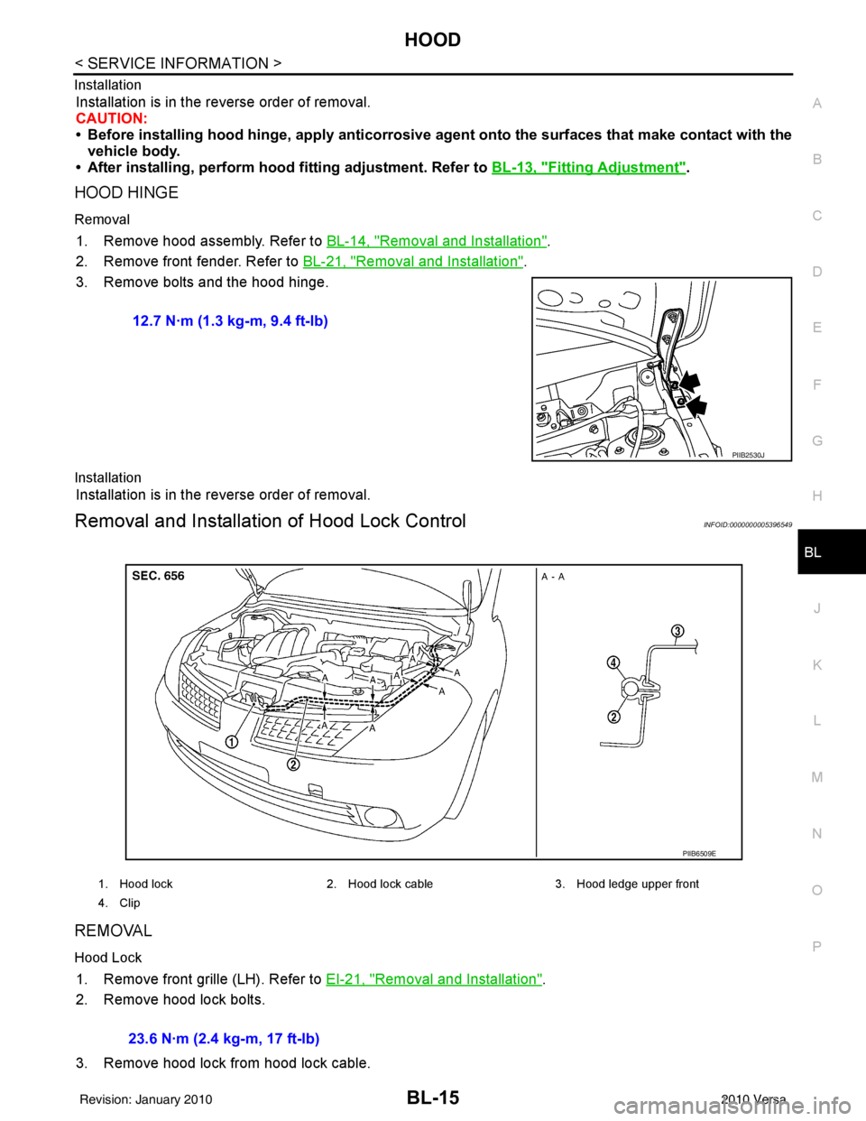
3. Remove bolts and the hood hinge.
Installation
Installation is in the reverse order of removal.
Removal and Installation of Hood Lock ControlINFOID:0000000005396549
REMOVAL
Hood Lock
1. Remove front grille (LH). Refer to EI-21, "Removal and Installation".
2. Remove hood lock bolts.
3. Remove hood lock from hood lock cable. 12.7 N·m (1.3 kg-m, 9.4 ft-lb)
PIIB2530J
1. Hood lock
2. Hood lock cable 3. Hood ledge upper front
4. Clip
PIIB6509E
23.6 N·m (2.4 kg-m, 17 ft-lb)
Revision: January 20102010 Versa
Page 525 of 3745
BL-16
< SERVICE INFORMATION >
HOOD
Hood Lock Reinforcement
1. Remove front bumper. Refer to EI-15, "Removal and Installation".
2. Remove crash zone sensor. Refer to SRS-42, "
Removal and Installation".
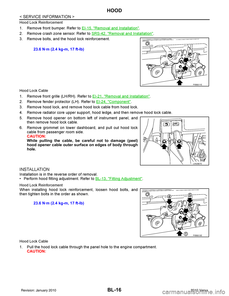
3. Remove bolts, and the hood lock reinforcement.
Hood Lock Cable
1. Remove front grille (LH/RH). Refer to EI-21, "Removal and Installation".
2. Remove fender protector (LH). Refer to EI-24, "
Component".
3. Remove hood lock, and remove hood lock cable from hood lock.
4. Remove radiator core upper support, hood ledge, and then remove hood lock cable.
5. Remove hood opener on bottom left of instrument panel, and then remove hood lock cable.
6. Remove grommet on lower dashboard, and pull out hood lock cable from passenger room side.
CAUTION:
While pulling the cable, be car eful not to damage (peel)
hood opener cable outer surface on edges of body through
hole.
INSTALLATION
Installation is in the reverse order of removal.
• Perform hood fitting adjustment. Refer to BL-13, "
Fitting Adjustment".
Hood Lock Reinforcement
When installing hood lock reinforcement, loosen hood bolts, and
then tighten bolts in the order as shown.
Hood Lock Cable
1. Pull the hood lock cable through the panel hole to the engine compartment. CAUTION: 23.6 N·m (2.4 kg-m, 17 ft-lb)
PIIB6511E
LIIA2667E
23.6 N·m (2.4 kg-m, 17 ft-lb)
PIIB6513E
Revision: January 20102010 Versa
Page 530 of 3745
FRONT FENDERBL-21
< SERVICE INFORMATION >
C
DE
F
G H
J
K L
M A
B
BL
N
O P
FRONT FENDER
Removal and InstallationINFOID:0000000005396552
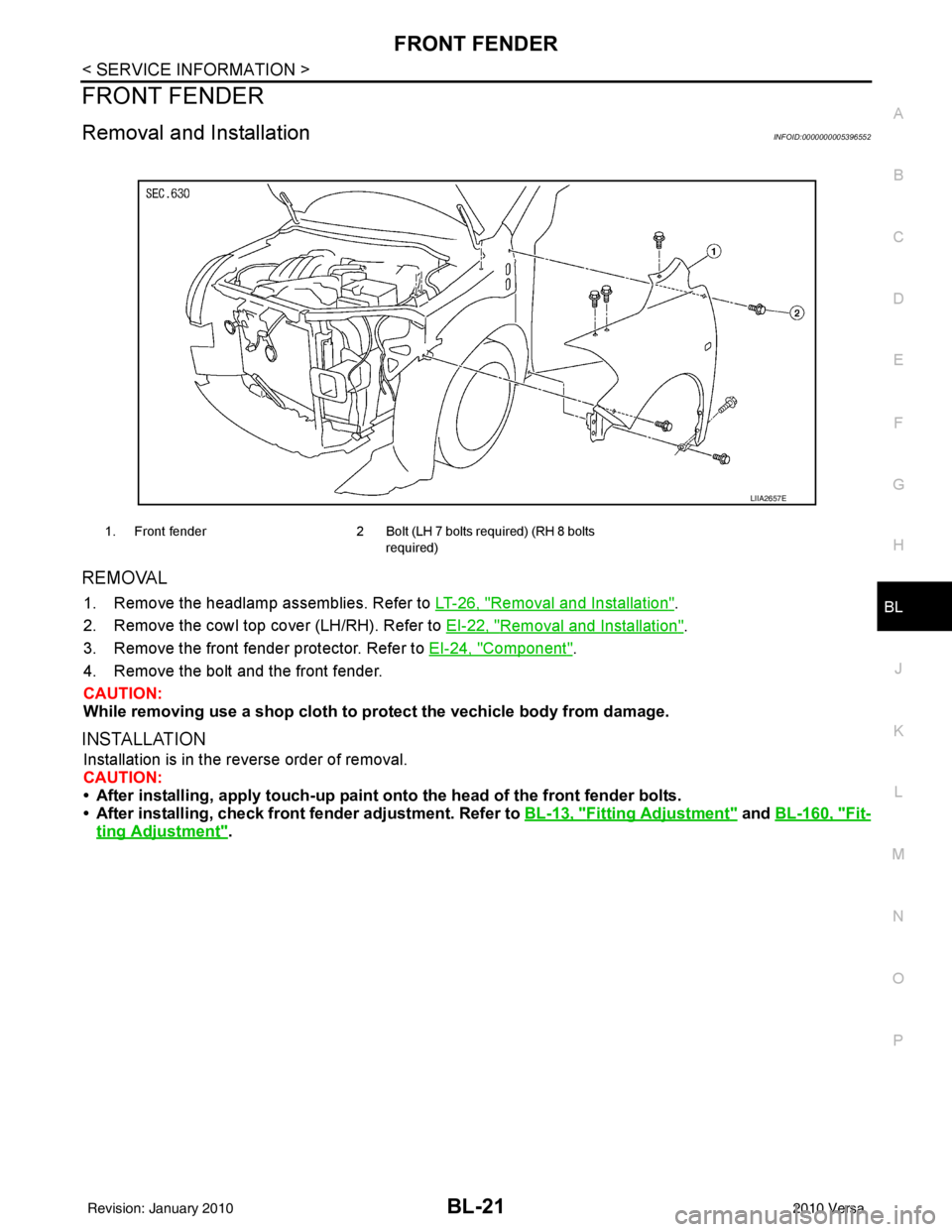
REMOVAL
1. Remove the headlamp assemblies. Refer to LT-26, "Removal and Installation".
2. Remove the cowl top cover (LH/RH). Refer to EI-22, "
Removal and Installation".
3. Remove the front fender protector. Refer to EI-24, "
Component".
4. Remove the bolt and the front fender.
CAUTION:
While removing use a shop cloth to pr otect the vechicle body from damage.
INSTALLATION
Installation is in the reverse order of removal.
CAUTION:
• After installing, apply touch-up paint on to the head of the front fender bolts.
• After installing, check front fender adjustment. Refer to BL-13, "
Fitting Adjustment" and BL-160, "Fit-
ting Adjustment".
1. Front fender 2 Bolt (LH 7 bolts required) (RH 8 bolts
required)
LIIA2657E
Revision: January 20102010 Versa
Page 532 of 3745

POWER DOOR LOCK SYSTEMBL-23
< SERVICE INFORMATION >
C
DE
F
G H
J
K L
M A
B
BL
N
O P
System DescriptionINFOID:0000000005396554
Power is supplied at all times
• through 40A fusible link (letter g , located in the fuse and fusible link box)
• to BCM terminal 70
• through 10A fuse [No. 8, located in the fuse block (J/B)]
• to BCM terminal 57
• through 10A fuse [No. 14, located in the fuse block (J/B)]
• to key switch terminal 2 (without Intelligent Key system)
• through 10A fuse [No. 31, located in the fuse block (J/B)]
• to key switch and ignition knob switch terminals 2 and 4 (with Intelligent Key system).
When key switch is ON (key is inserted in ignition key cylinder), power is supplied
• through key switch terminal 1 (without Intelligent Key system) or key switch and ignition knob terminal 1 (with Intelligent Key system)
• to BCM terminal 37.
Ground is supplied
• to BCM terminal 67
• through body grounds M57 and M61.
LOCK OPERATION
When the door is locked with main power window and door lock/unlock switch, ground is supplied
• to BCM terminal 45
• through main power window and door lock and unlock switch terminals 17 and 18
• through body grounds M57 and M61.
When the door is locked with power window and door lock/unlock switch RH, ground is supplied
• to BCM terminal 45
• through power window and door lock and unlock switch RH terminals 1 and 3
• through body grounds M57 and M61.
When the door is locked with front door ke y cylinder switch LH, ground is supplied
• to BCM terminal 8
• through front door key cylinder switch LH terminals 1 and 2
• through body grounds M57 and M61.
UNLOCK OPERATION
When the door is unlocked with main power window and door lock/unlock switch, ground is supplied
• to BCM terminal 46
• through main power window and door lock/unlock switch terminals 6 and 17
• through body grounds M57 and M61.
When the door is unlocked with power window and door lock/unlock switch RH, ground is supplied
• to BCM terminal 46
• through power window and door lock and unlock switch RH terminals 2 and 3
• through body grounds M57 and M61.
When the door is unlocked with front door ke y cylinder switch LH, ground is supplied
• to BCM terminal 7
• through front door key cylinder switch LH terminals 2 and 3
• through body grounds M57 and M61.
When the front door switch LH is ON (door is OPEN), ground is supplied
• to BCM terminal 47
• through front door switch LH terminal 2
• through front door switch LH case ground.
When the front door switch RH is ON (door is OPEN), ground is supplied
• to BCM terminal 12
• through front door switch RH terminal 2
• through front door switch RH case ground.
10. Key switch and key lock solenoid M27
(without Intelligent key) 11. Main power window and door lock/un-
lock switch D7, D8
Power window and door lock/unlock
switch RH D105 12. Fuse block (with Intelligent Key)
(view with instrument panel LH re-
moved)
13. Passenger select unlock relay M2 (with Intelligent Key) 14. Back door lock assembly (back door
switch) D405 (hatchback view with back
door open) 15. Combination meter M24
Revision: January 20102010 Versa
Page 533 of 3745

BL-24
< SERVICE INFORMATION >
POWER DOOR LOCK SYSTEM
When the rear door switch LH is ON (door is OPEN), ground is supplied
• to BCM terminal 48
• through rear door switch LH terminal 1
• through rear door switch LH case ground.
When the rear door switch RH is ON (door is OPEN), ground is supplied
• to BCM terminal 13
• through rear door switch RH terminal 1
• through rear door switch RH case ground.
When the back door switch (hatchback) is ON (back door is OPEN), ground is supplied
• to BCM terminal 43
• through back door switch terminals 3 and 4
• through body grounds B117, B132 and D402.
OUTLINE
Functions available by operating the inside door lock and unlock switches
• Interlocked with the locking operation of door lock and unlock switch, door lock actuators of all doors and
trunk (sedan) are locked.
• Interlocked with the unlocking operation of door lock and unlock switch, door lock actuators of all doors and
trunk (sedan) are unlocked.
Functions available by operating t he front door key cylinder switch LH
• Interlocked with the locking operation of front door key cylinder switch LH, door lock actuators of all doors
and trunk (sedan) are locked.
• When front door key cylinder switch LH is unlo cked, front door lock actuator LH is unlocked.
• When front door key cylinder switch LH is unlocked for the second time within 5 seconds after the first oper- ation, door lock actuators on all doors and trunk (sedan) are unlocked.
Key reminder door system
When door lock and unlock switch is operated to lock doors with ignition key inserted in key cylinder and any
door open, all door lock actuators are locked and then unlocked.
AUTOMATIC DOOR LOCKS (LOCK OPERATION)
The interlock door lock function is the function that locks all doors linked with the vehicle speed.
Vehicle Speed Sensing Auto Door Lock*1
All doors are locked when the vehicle speed reaches 24 km/h (15 MPH) or more.
BCM outputs the lock signal to all door lock actuators when it detects that the ignition switch is turned ON, all
doors are closed and the vehicle speed received from the combination meter via CAN communication
becomes 15 MPH (24 km/h) or more.
If a door is opened and closed at any time during one ignition cycle (OFF → ON), even after initial auto door
lock has taken place, the BCM will relock all doors when the vehicle speed reaches 15 MPH (24 km/h) or more
again.
Setting change of Automatic Door Locks (LOCK) Function
The lock operation setting of the autom atic door locks function can be changed.
With CONSULT-III
The ON/OFF switching of the automatic door locks (LOC K) function and the type selection of the automatic
door locks (LOCK) function can be performed at the WO RK SUPPORT setting of CONSULT-III. Refer to BL-
41, "CONSULT-III Function (BCM)".
Without CONSULT- III
The automatic door locks (LOCK) function can be swit ched ON/OFF by performing the following operation.
1. Close all doors (door switch OFF).
2. Turn ignition switch ON.
3. Within 20 seconds of turning the ignition switch ON, press and hold the door lock and unlock switch to the LOCK position for more than 5 seconds.
4. The switching is completed when the hazard lamps blink.
5. The ignition switch must be turned OFF and ON again between each setting change.
OFF → ON : 2 blinks
ON → OFF : 1 blink
Revision: January 20102010 Versa
Page 561 of 3745
BL-52
< SERVICE INFORMATION >
POWER DOOR LOCK SYSTEM
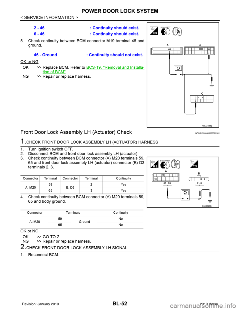
5. Check continuity between BCM connector M19 terminal 46 andground.
OK or NG
OK >> Replace BCM. Refer to BCS-19, "Removal and Installa-
tion of BCM" .
NG >> Repair or replace harness.
Front Door Lock Assembly LH (Actuator) CheckINFOID:0000000005396569
1.CHECK FRONT DOOR LOCK ASSEMBLY LH (ACTUATOR) HARNESS
1. Turn ignition switch OFF.
2. Disconnect BCM and front door lock assembly LH (actuator).
3. Check continuity between BCM connector (A) M20 terminals 59, 65 and front door lock assembly LH (actuator) connector (B) D3
terminals 2, 3.
4. Check continuity between BCM connector (A) M20 terminals 59, 65 and body ground.
OK or NG
OK >> GO TO 2
NG >> Repair or replace harness.
2.CHECK FRONT DOOR LOCK ASSEMBLY LH SIGNAL
1. Reconnect BCM. 2 - 46
: Continuity should exist.
6 - 46 : Continuity should exist.
46 - Ground : Continuity should not exist.
WIIA1111E
Connector Terminal Connector Terminal Continuity
A: M20 59
B: D3 2Y
es
65 3Yes
Connector Terminals Continuity
A: M20 59
Ground No
65 No
LIIA2525E
Revision: January 20102010 Versa
Page 562 of 3745
POWER DOOR LOCK SYSTEMBL-53
< SERVICE INFORMATION >
C
DE
F
G H
J
K L
M A
B
BL
N
O P
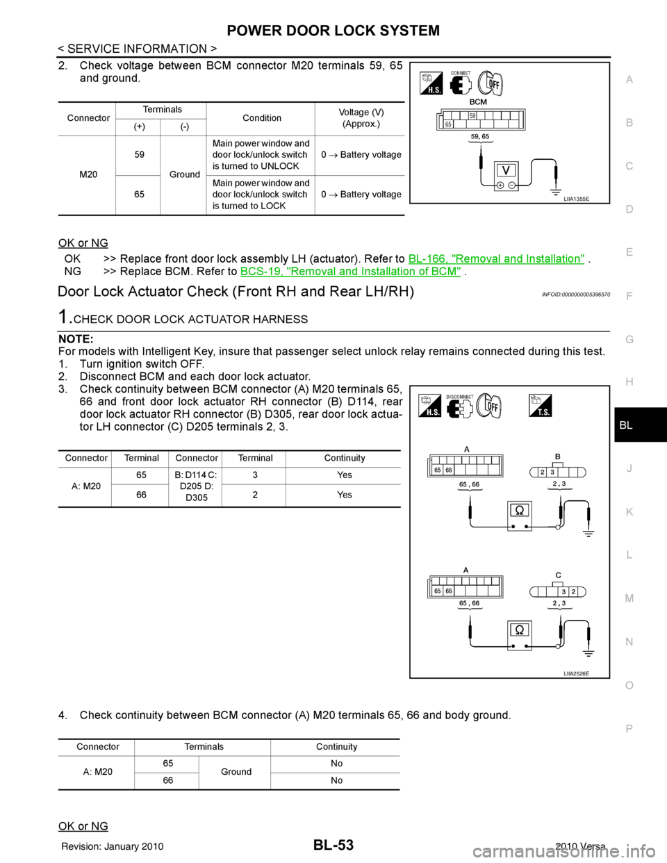
2. Check voltage between BCM connector M20 terminals 59, 65 and ground.
OK or NG
OK >> Replace front door lock assembly LH (actuator). Refer to BL-166, "Removal and Installation" .
NG >> Replace BCM. Refer to BCS-19, "
Removal and Installation of BCM" .
Door Lock Actuator Check (Front RH and Rear LH/RH)INFOID:0000000005396570
1.CHECK DOOR LOCK ACTUATOR HARNESS
NOTE:
For models with Intelligent Key, insure that passenger select unlock relay remains connected during this test.
1. Turn ignition switch OFF.
2. Disconnect BCM and each door lock actuator.
3. Check continuity between BCM connector (A) M20 terminals 65, 66 and front door lock actuator RH connector (B) D114, rear
door lock actuator RH connector (B ) D305, rear door lock actua-
tor LH connector (C) D205 terminals 2, 3.
4. Check continuity between BCM connecto r (A) M20 terminals 65, 66 and body ground.
OK or NG
Connector Te r m i n a l s
ConditionVoltage (V)
(Approx.)
(+) (-)
M20 59
Ground Main power window and
door lock/unlock switch
is turned to UNLOCK
0
→ Battery voltage
65 Main power window and
door lock/unlock switch
is turned to LOCK 0
→ Battery voltage
LIIA1355E
Connector Terminal Connector Terminal Continuity
A: M20 65 B: D114 C:
D205 D:
D305 3Y
es
66 2Yes
LIIA2526E
Connector Terminals Continuity
A: M20 65
Ground No
66 No
Revision: January 20102010 Versa
Page 564 of 3745
POWER DOOR LOCK SYSTEMBL-55
< SERVICE INFORMATION >
C
DE
F
G H
J
K L
M A
B
BL
N
O P
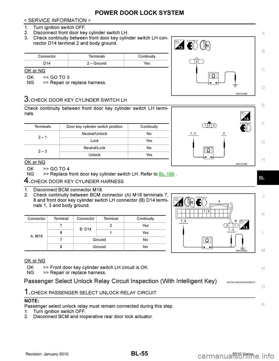
1. Turn ignition switch OFF.
2. Disconnect front door key cylinder switch LH.
3. Check continuity between front door key cylinder switch LH con- nector D14 terminal 2 and body ground.
OK or NG
OK >> GO TO 3
NG >> Repair or replace harness.
3.CHECK DOOR KEY CYLINDER SWITCH LH
Check continuity between front door key cylinder switch LH termi-
nals.
OK or NG
OK >> GO TO 4
NG >> Replace front door key cylinder switch LH. Refer to BL-166
.
4.CHECK DOOR KEY CYLINDER HARNESS
1. Disconnect BCM connector M18.
2. Check continuity between BCM connector (A) M18 terminals 7, 8 and front door key cylinder switch LH connector (B) D14 termi-
nals 1, 3 and body ground.
OK or NG
OK >> Front door key cylinder switch LH circuit is OK.
NG >> Repair or replace harness.
Passenger Select Unlock Relay Circuit Inspection (With Intelligent Key)INFOID:0000000005396572
1.CHECK PASSENGER SELECT UNLOCK RELAY CIRCUIT
NOTE:
Passenger select unlock relay must remain connected during this step.
1. Turn ignition switch OFF.
2. Disconnect BCM and inoperative rear door lock actuator.
Connector TerminalsContinuity
D14 2 – Ground Yes
WIIA1248E
Terminals Door key cylinder switch position Continuity
2 – 1 Neutral/Unlock
No
Lock Yes
2 – 3 Neutral/Lock
No
Unlock Yes
WIIA1249E
Connector Terminal Connector Terminal Continuity
A: M18 7
B: D14 3Y
es
81Y es
7G ro un d N o
8G ro un d N o
WIIA1250E
Revision: January 20102010 Versa