motor NISSAN TIIDA 2010 Service Repair Manual
[x] Cancel search | Manufacturer: NISSAN, Model Year: 2010, Model line: TIIDA, Model: NISSAN TIIDA 2010Pages: 3745, PDF Size: 73.67 MB
Page 3506 of 3745

RF-22
< ON-VEHICLE REPAIR >
SUNROOF
ON-VEHICLE REPAIR
SUNROOF
Removal and InstallationINFOID:0000000005396810
CAUTION:
• After installation or any adjustment, check clearances for sunroof operation and glass lid alignment.
• Handle glass lid with care to prevent damage.
• Fully close the glass lid before removal, then do not operate sunroof motor assembly after removal.
• When removing sunroof unit assembly, use shop cl oths to protect the seats and trim from damage.
• Always work with a helper.
NOTE:
For easy installation, mark each point before removal.
Revision: January 20102010 Versa
Page 3507 of 3745

SUNROOFRF-23
< ON-VEHICLE REPAIR >
C
DE
F
G H
J
K L
M A
B
RF
N
O P
SUNROOF UNIT ASSEMBLY
1. Glass lid 2. Rear drain assembly3. Link assembly (RH)
4. Sunroof bracket 5. Wind deflector6. Drain hose
7. Sunroof unit assembly 8. Sunroof motor assembly9. Sunshade
10. Sunshade stopper 11. Link assembly (LH) Vehicle front
WIIA1243E
Revision: January 20102010 Versa
Page 3508 of 3745

RF-24
< ON-VEHICLE REPAIR >
SUNROOF
Removal
1. Tilt glass lid up, then remove. Follow the GLASS LID procedure.
2. Position sunroof unit assembly to the fully closed position.
3. Remove the headlining. Refer to EI-48, "
Component".
4. Disconnect drain hoses.
5. Remove the screws, then disconnect the sunroof motor assem- bly.
NOTE:
• Before removing sunroof motor assembly, make sure that sun-
roof is fully closed.
• After removing sunroof motor assembly, do not attempt to
rotate sunroof motor as a single unit.
6. Remove the side and front sunroof unit assembly nuts.
7. Remove sunroof bracket bolts, then remove sunroof unit assem- bly from roof panel.
• Remove sunroof unit assembly through the passenger com-partment.
CAUTION:
Use care during assembly removal and installation to avoid
damage to seats and trim.
Installation
1. Install sunroof brackets and bolts to the roof panel side only, but do not tighten.
2. Bring sunroof unit assembly into passenger compartment and position it so the rear rests on the sunroof brackets.
3. Install sunroof bracket bolts to the sunroof unit assembly side, but do not tighten.
PIIB4745J
PIIB4747J
PIIB4748J
PIIB4748J
Revision: January 20102010 Versa
Page 3509 of 3745

SUNROOFRF-25
< ON-VEHICLE REPAIR >
C
DE
F
G H
J
K L
M A
B
RF
N
O P
4. Install the front and side sunroof unit assembly nuts, but do not tighten.
5. Tighten the sunroof unit assembly.
a. First, tighten the sunroof bracket bolts at the vehicle side, then tighten the bolt on the rail side.
b. Next, tighten the front and side sunroof unit assembly nuts diag- onally.
6.7. Connect the sunroof motor assembly connector and install thescrews.
8. Install the glass lid. Follow the GLASS LID procedure.
9. Connect drain hoses.
10. Install headlining. Refer to EI-48, "
Component".
11. Perform fitting adjustment and test for leaks, refer to RF-27, "
Fitting Adjustment" .
GLASS LID
Removal
1. Open the sunshade fully and close the glass lid.
2. Remove glass lid bolts, then remove glass lid.
Installation
PIIB4746J
PIIB4748J
PIIB4745J
PIIB4749J
Revision: January 20102010 Versa
Page 3510 of 3745

RF-26
< ON-VEHICLE REPAIR >
SUNROOF
1. Position the glass lid on sunroof unit assembly.
2. Partially install glass lid bolts. Tighten left front bolt first, then right rear to prevent uneven torque while
tightening remaining bolts.
3. After installation, check sunroof operation and glass lid assembly alignment. Refer to RF-27, "
Fitting
Adjustment" .
SUNSHADE
Removal
1. Remove the headlining. Refer to EI-48, "Component".
2. Remove sunshade stopper RH/LH.
3. Pull sunshade out rear of sunroof frame to remove it from sun- roof unit assembly frame.
Installation
Installation is in the reverse order of removal.
WIND DEFLECTOR
Removal
1. Open the glass lid.
2. Remove spring retainer screws RH/LH, then slide retainer for-
ward in vehicle out of sunroof unit assembly channel.
3. Lift wind deflector and rotate arms upward to release from sun- roof unit assembly.
Installation
Installation is in the reverse order of removal.
SUNROOF MOTOR ASSEMBLY
Removal
1. Close the glass lid.
2. Remove headlining. Refer to EI-48, "
Component".
3. Remove sunroof motor assembly screws.
4. Disconnect harness connector from sunroof motor assembly, then remove sunroof motor assembly.
CAUTION:
• When removing the sunroof motor assembly, be sure that
the sunroof lid is in th e fully closed position.
• Do not operate the removed sunroof motor assembly as a
single unit.
Installation
PIIB4750J
PIIB4751J
PIIB4745J
Revision: January 20102010 Versa
Page 3511 of 3745

SUNROOFRF-27
< ON-VEHICLE REPAIR >
C
DE
F
G H
J
K L
M A
B
RF
N
O P
CAUTION:
• Before installing the sunroof motor assembly, be su re the link assembly is in the symmetrical and
fully closed position.
• Align the link notch with the hole of the guide track (fully closed: RH and LH).
1. Place the sunroof motor assembly flat onto the sunroof unit assembly surface.
2. Laterally move the assembly little by little so that the gear is completely engaged into the wire and there is no gap between the sunroof unit assembly and sunroof motor assembly.
3. Install the sunroof motor assembly screws, then connect the harness connector.
4. After installing, perform the initialization procedure. Refer to RF-11, "
System Description" .
LINK ASSEMBLY
Removal
1. Remove sunroof unit assembly. Follow the SUNROOF UNIT ASSEMBLY procedure.
2. Remove screws, then remove rear drain assembly.
3. Remove sunroof motor assembly. Follow the SUNROOF MOTOR ASSEMBLY procedure.
4. Remove link assembly from the rear end of the sunroof frame.
Installation
Installation is in the reverse order of removal.
Fitting AdjustmentINFOID:0000000005396811
GAP ADJUSTMENT
1. Tilt up glass lid.
2. Loosen glass lid bolts, then tilt down glass lid.
3. Adjust glass lid from outside of vehicle so it resembles “A–A” “B–
B” “C–C” as shown in the figure.
• For gap adjustment "A-A" "C-C", carefully slide glass lid for-
ward and rearward in vehicle.
• For gap adjustment "B-B", loosen sunroof unit assembly and
shift side to side.
NOTE:
To prevent glass lid from moving after adjustment, lightly tighten
the bolts.
4. Tighten left front bolt, then right rear bolt to prevent uneven torque. Tighten remaining bolts, being careful to prevent glass
lid from moving.
5. Tilt glass lid up and down several times to check that it moves smoothly, and retains the adjustment.
PIIB2457E
ab c
A–A 5.8 mm (0.228 in) 0.75 ± 1.5 mm (0.03 ± 0.059 in) 1.4 ± 0.8 mm (0.055 ± 0.031 in)
B–B 5.8mm (0.228 in) 0.75 ± 1.5 mm (0.03 ± 0.059 in) 1.4 ± 0.8 mm (0.055 ± 0.031 in)
C–C 5.8mm (0.228 in) 0.75 ± 1.5 mm (0.03 ± 0.059 in) 1.4 ± 0.8 mm (0.055 ± 0.031 in)
PIIB4749J
Revision: January 20102010 Versa
Page 3548 of 3745

STARTING SYSTEMSC-9
< SERVICE INFORMATION >
C
DE
F
G H
I
J
L
M A
B
SC
N
O P
STARTING SYSTEM
System DescriptionINFOID:0000000005394861
M/T Models
Power is supplied at all times
• to starter motor terminal B, and
• through 40A fusible link (letter h, located in the fuse and fusible link box)
• to ignition switch terminal B.
With the ignition switch in the START position, power is supplied
• from ignition switch terminal ST
• to IPDM E/R terminal 21.
With the ignition switch in the ON or START position, power is supplied
• through 10A fuse (No. 49, located in the IPDM E/R)
• to the clutch interlock switch terminal 1.
With the clutch pedal depressed, power is supplied
• through the clutch interlock switch terminal 2
• to IPDM E/R terminal 35.
Ground is supplied at all times
• to IPDM E/R terminals 39 and 59
• through body grounds E15 and E24.
If the IPDM E/R receives a starter relay request ON signal from the BCM over the CAN communication lines,
the IPDM E/R grounds the starter relay and power is supplied
• through terminal 19 of the IPDM E/R
• to terminal S of the starter motor.
The starter motor magnetic switch energizes closing the circuit between the battery and the starter motor. The
starter motor is case ground through the cylinder block. With power and ground supplied, the starter motor
operates.
A/T Models
Power is supplied at all times
• to starter motor terminal B, and
• through 40A fusible link (letter h, located in the fuse and fusible link box)
• to ignition switch terminal B.
With the ignition switch in the START position, power is supplied
• from ignition switch terminal ST
• to IPDM E/R terminal 21.
With the ignition switch in the ON or START position, power is supplied
• through 10A fuse (No. 54, located in the IPDM E/R)
• to transmission range switch terminal 1.
With the selector lever in the P or N position, power is supplied
• through transmission range switch terminal 2
• to IPDM E/R terminal 35.
Ground is supplied at all times
• to IPDM E/R terminals 39 and 59
• through body grounds E15 and E24.
If the IPDM E/R receives a starter relay request ON signal from the BCM over the CAN communication lines,
the IPDM E/R grounds the starter relay and power is supplied
• through terminal 19 of the IPDM E/R
• to terminal S of the starter motor.
The starter motor magnetic switch energizes closing the circuit between the battery and the starter motor. The
starter motor is case ground through the cylinder block. With power and ground supplied, the starter motor
operates.
CVT Models
Power is supplied at all times
• to starter motor terminal B, and
• through 40A fusible link (letter h, located in the fuse and fusible link box)
• to ignition switch terminal B.
With the ignition switch in the START position, power is supplied
• from ignition switch terminal ST
Revision: January 20102010 Versa
Page 3549 of 3745

SC-10
< SERVICE INFORMATION >
STARTING SYSTEM
• to IPDM E/R terminal 21.
With the selector lever in the P or N position, power is supplied
• from the transmission control module (TCM) terminal 24
• to IPDM E/R terminal 35.
Ground is supplied at all times
• to IPDM E/R terminals 39 and 59
• through body grounds E15 and E24.
If the IPDM E/R receives a starter relay request ON signal from the BCM over the CAN network, the IPDM E/
R grounds the starter relay and power is supplied
• through terminal 19 of the IPDM E/R
• to terminal S of the starter motor.
The starter motor magnetic switch energizes closing the circuit between the battery and the starter motor. The
starter motor is case ground through the cylinder block. With power and ground supplied, the starter motor
operates.
Revision: January 20102010 Versa
Page 3556 of 3745
STARTING SYSTEMSC-17
< SERVICE INFORMATION >
C
DE
F
G H
I
J
L
M A
B
SC
N
O P
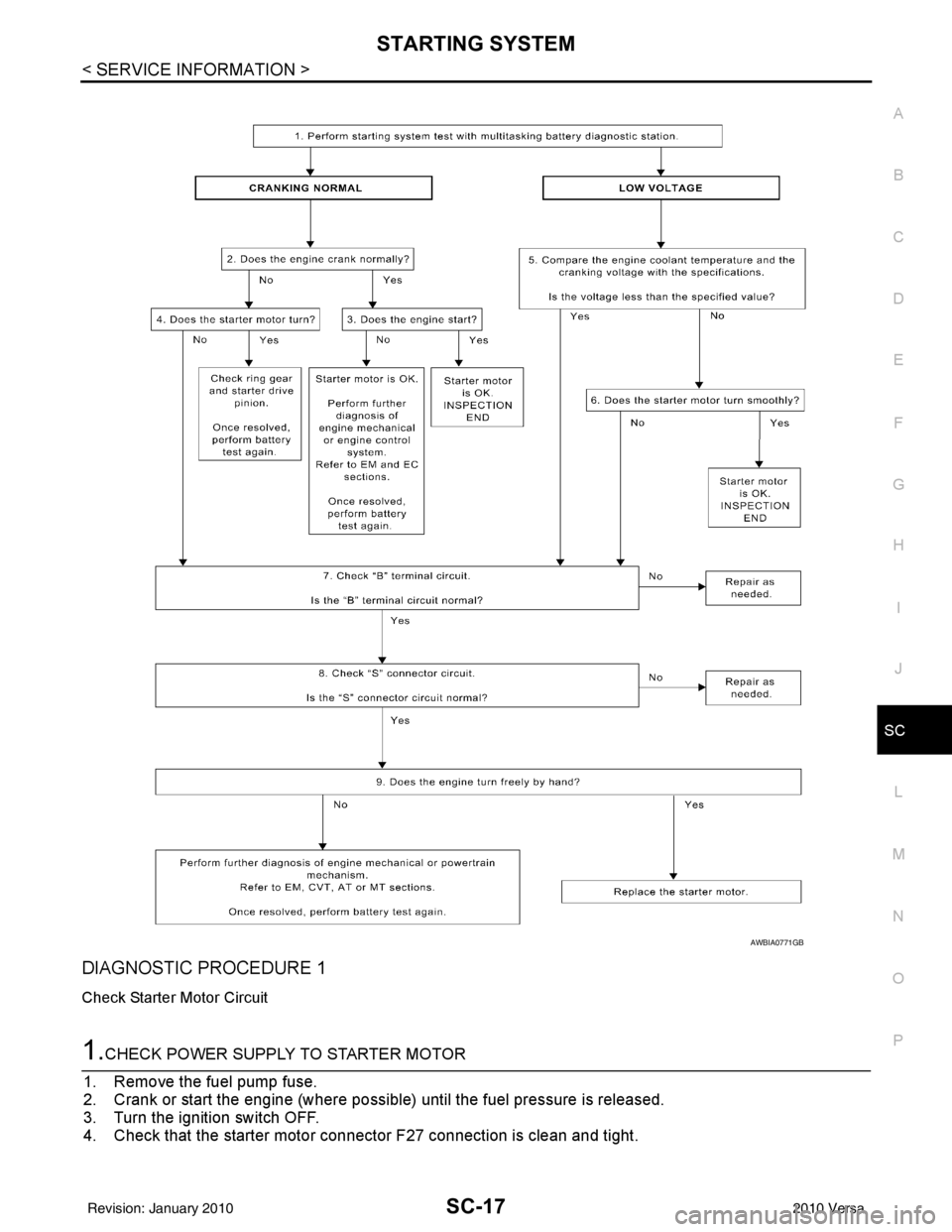
DIAGNOSTIC PROCEDURE 1
Check Starter Motor Circuit
1.CHECK POWER SUPPLY TO STARTER MOTOR
1. Remove the fuel pump fuse.
2. Crank or start the engine (where possible) until the fuel pressure is released.
3. Turn the ignition switch OFF.
4. Check that the starter motor connector F27 connection is clean and tight.
AWBIA0771GB
Revision: January 20102010 Versa
Page 3557 of 3745
SC-18
< SERVICE INFORMATION >
STARTING SYSTEM
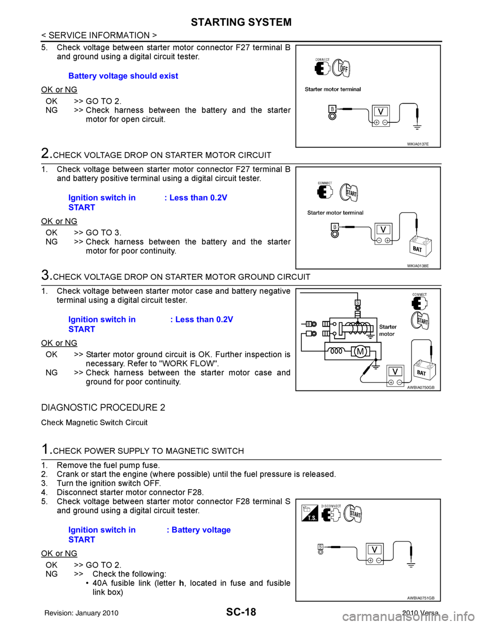
5. Check voltage between starter motor connector F27 terminal Band ground using a digital circuit tester.
OK or NG
OK >> GO TO 2.
NG >> Check harness between the battery and the starter motor for open circuit.
2.CHECK VOLTAGE DROP ON STARTER MOTOR CIRCUIT
1. Check voltage between starter motor connector F27 terminal B and battery positive terminal using a digital circuit tester.
OK or NG
OK >> GO TO 3.
NG >> Check harness between the battery and the starter motor for poor continuity.
3.CHECK VOLTAGE DROP ON STARTER MOTOR GROUND CIRCUIT
1. Check voltage between starter motor case and battery negative terminal using a digital circuit tester.
OK or NG
OK >> Starter motor ground circuit is OK. Further inspection is necessary. Refer to "WORK FLOW".
NG >> Check harness between the starter motor case and
ground for poor continuity.
DIAGNOSTIC PROCEDURE 2
Check Magnetic Switch Circuit
1.CHECK POWER SUPPLY TO MAGNETIC SWITCH
1. Remove the fuel pump fuse.
2. Crank or start the engine (where possible) until the fuel pressure is released.
3. Turn the ignition switch OFF.
4. Disconnect starter motor connector F28.
5. Check voltage between starter motor connector F28 terminal S and ground using a digital circuit tester.
OK or NG
OK >> GO TO 2.
NG >> Check the following: • 40A fusible link (letter h, located in fuse and fusible
link box)
Battery voltage should exist
WKIA0137E
Ignition switch in
START
: Less than 0.2V
WKIA0138E
Ignition switch in
START : Less than 0.2V
AWBIA0750GB
Ignition switch in
START: Battery voltage
AWBIA0751GB
Revision: January 20102010 Versa