coolant level NISSAN TIIDA 2010 Service Owner's Manual
[x] Cancel search | Manufacturer: NISSAN, Model Year: 2010, Model line: TIIDA, Model: NISSAN TIIDA 2010Pages: 3745, PDF Size: 73.67 MB
Page 1732 of 3745
ECM
EC-467
< ECU DIAGNOSIS > [HR16DE]
C
D
E
F
G H
I
J
K L
M A
EC
NP
O
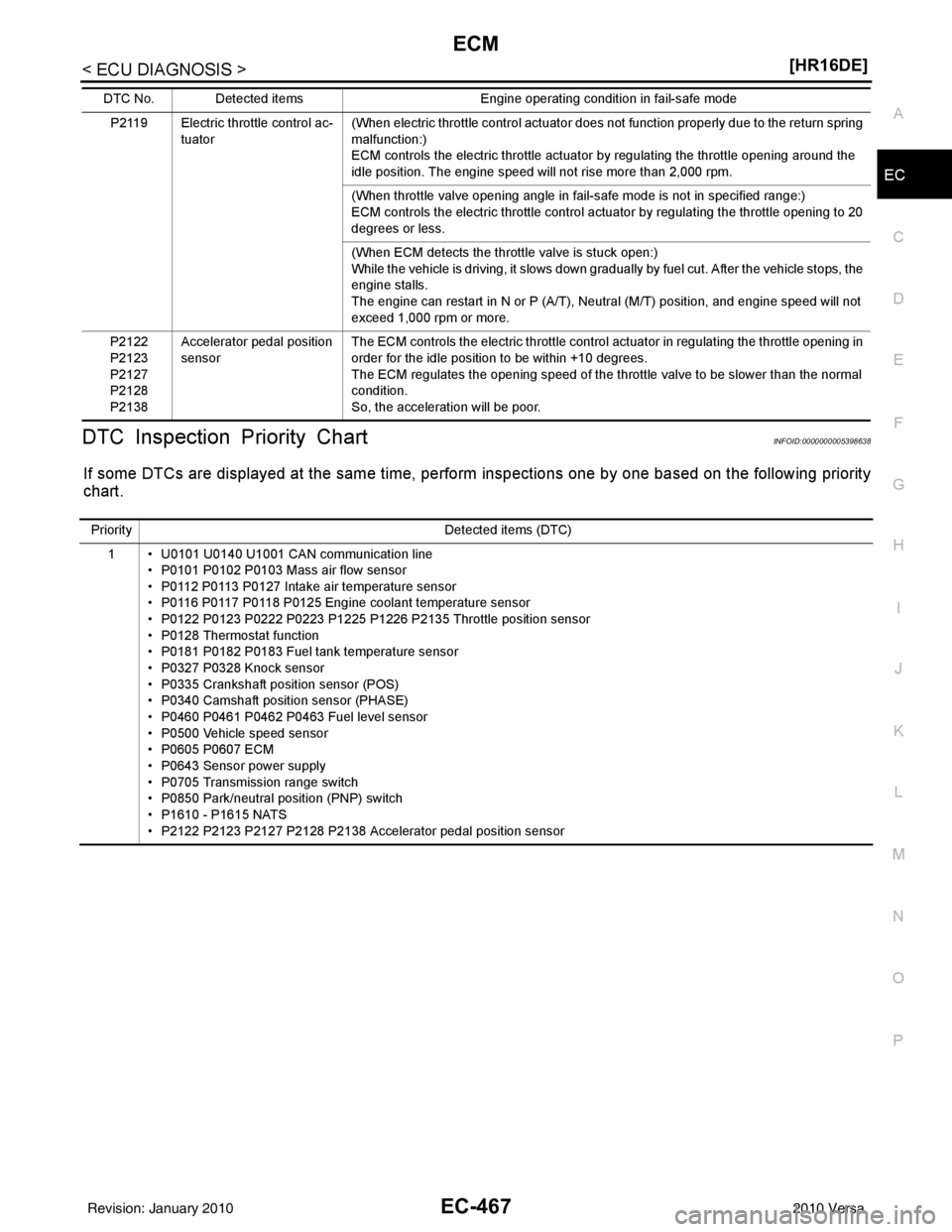
DTC Inspection Priority ChartINFOID:0000000005398638
If some DTCs are displayed at the same time, perform inspections one by one based on the following priority
chart.
P2119 Electric thro
ttle control ac-
tuator (When electric throttle control actuator does not function properly due to the return spring
malfunction:)
ECM controls the electric throttle actuator by regulating the throttle opening around the
idle position. The engine speed will not rise more than 2,000 rpm.
(When throttle valve opening angle in fail-safe mode is not in specified range:)
ECM controls the electric throttle control actuator by regulating the throttle opening to 20
degrees or less.
(When ECM detects the throttle valve is stuck open:)
While the vehicle is driving, it slows down gradually by fuel cut. After the vehicle stops, the
engine stalls.
The engine can restart in N or P (A/T), Neutral (M/T) position, and engine speed will not
exceed 1,000 rpm or more.
P2122
P2123
P2127
P2128
P2138 Accelerator pedal position
sensor
The ECM controls the electric throttle control actuator in regulating the throttle opening in
order for the idle position to be within +10 degrees.
The ECM regulates the opening speed of the throttle valve to be slower than the normal
condition.
So, the acceleration will be poor.
DTC No. Detected items
Engine operating condition in fail-safe mode
PriorityDetected items (DTC)
1 • U0101 U0140 U1001 CAN communication line • P0101 P0102 P0103 Mass air flow sensor
• P0112 P0113 P0127 Intake air temperature sensor
• P0116 P0117 P0118 P0125 Engine coolant temperature sensor
• P0122 P0123 P0222 P0223 P1225 P1226 P2135 Throttle position sensor
• P0128 Thermostat function
• P0181 P0182 P0183 Fuel tank temperature sensor
• P0327 P0328 Knock sensor
• P0335 Crankshaft position sensor (POS)
• P0340 Camshaft position sensor (PHASE)
• P0460 P0461 P0462 P0463 Fuel level sensor
• P0500 Vehicle speed sensor
• P0605 P0607 ECM
• P0643 Sensor power supply
• P0705 Transmission range switch
• P0850 Park/neutral position (PNP) switch
• P1610 - P1615 NATS
• P2122 P2123 P2127 P2128 P2138 Accelerator pedal position sensor
Revision: January 20102010 Versa
Page 1738 of 3745
ECM
EC-473
< ECU DIAGNOSIS > [HR16DE]
C
D
E
F
G H
I
J
K L
M A
EC
NP
O
• Sea level
• Flat road
• Ambient air temperature: 20 - 30
°C (68 - 86 °F)
• Diagnosis is performed as quickly as possible under normal conditions. Under different conditions [For example: ambient air temperature other than 20 - 30 °C (68 - 86° F)], diagno-
sis may also be performed.
Pattern 1:
• The engine is started at the engine coolant temperature of −10 to 35 °C (14 to 95 °F)
(where the voltage between the ECM te rminal 38 and ground is 3.0 - 4.3 V).
• The engine must be operated at idle speed until the engine coolant temperature is greater than 70 °C
(158° F) (where the voltage between the ECM te rminal 38 and ground is lower than 1.4 V).
• The engine is started at the fuel tank temperature of warmer than 0 °C (32° F) (where the voltage
between the ECM terminal 43 and ground is less than 4.1 V).
Pattern 2:
• When steady-state driving is performed again even afte r it is interrupted, each diagnosis can be conducted.
In this case, the time required for diagnosis may be extended.
Pattern 3:
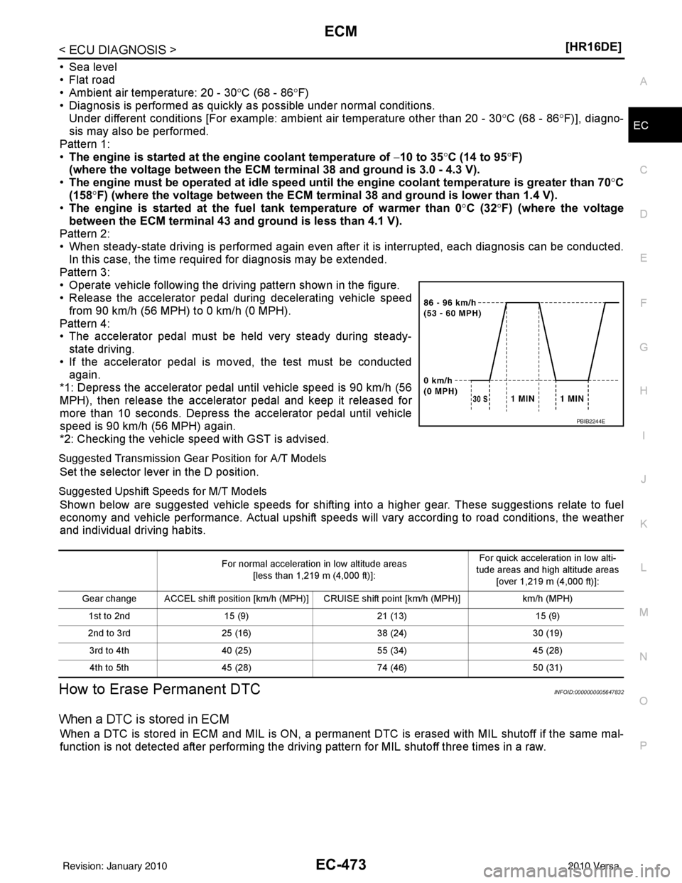
• Operate vehicle following the driving pattern shown in the figure.
• Release the accelerator pedal during decelerating vehicle speed from 90 km/h (56 MPH) to 0 km/h (0 MPH).
Pattern 4:
• The accelerator pedal must be held very steady during steady- state driving.
• If the accelerator pedal is moved, the test must be conducted again.
*1: Depress the accelerator pedal until vehicle speed is 90 km/h (56
MPH), then release the accelerator pedal and keep it released for
more than 10 seconds. Depress the accelerator pedal until vehicle
speed is 90 km/h (56 MPH) again.
*2: Checking the vehicle speed with GST is advised.
Suggested Transmission Gear Position for A/T Models
Set the selector lever in the D position.
Suggested Upshift Speeds for M/T Models
Shown below are suggested vehicle speeds for shifting into a higher gear. These suggestions relate to fuel
economy and vehicle performance. Actual upshift speeds will vary according to road conditions, the weather
and individual driving habits.
How to Erase Permanent DTCINFOID:0000000005647832
When a DTC is stored in ECM
When a DTC is stored in ECM and MIL is ON, a permanent DTC is erased with MIL shutoff if the same mal-
function is not detected after performing the drivi ng pattern for MIL shutoff three times in a raw.
PBIB2244E
For normal acceleration in low altitude areas
[less than 1,219 m (4,000 ft)]: For quick acceleration in low alti-
tude areas and high altitude areas [over 1,219 m (4,000 ft)]:
Gear change ACCEL shift positi on [km/h (MPH)] CRUISE shift point [km/h (MPH)]km/h (MPH)
1st to 2nd 15 (9) 21 (13) 15 (9)
2nd to 3rd 25 (16) 38 (24)30 (19)
3rd to 4th 40 (25) 55 (34)45 (28)
4th to 5th 45 (28) 74 (46)50 (31)
Revision: January 20102010 Versa
Page 1752 of 3745
ENGINE CONTROL SYSTEM SYMPTOMSEC-487
< SYMPTOM DIAGNOSIS > [HR16DE]
C
D
E
F
G H
I
J
K L
M A
EC
NP
O
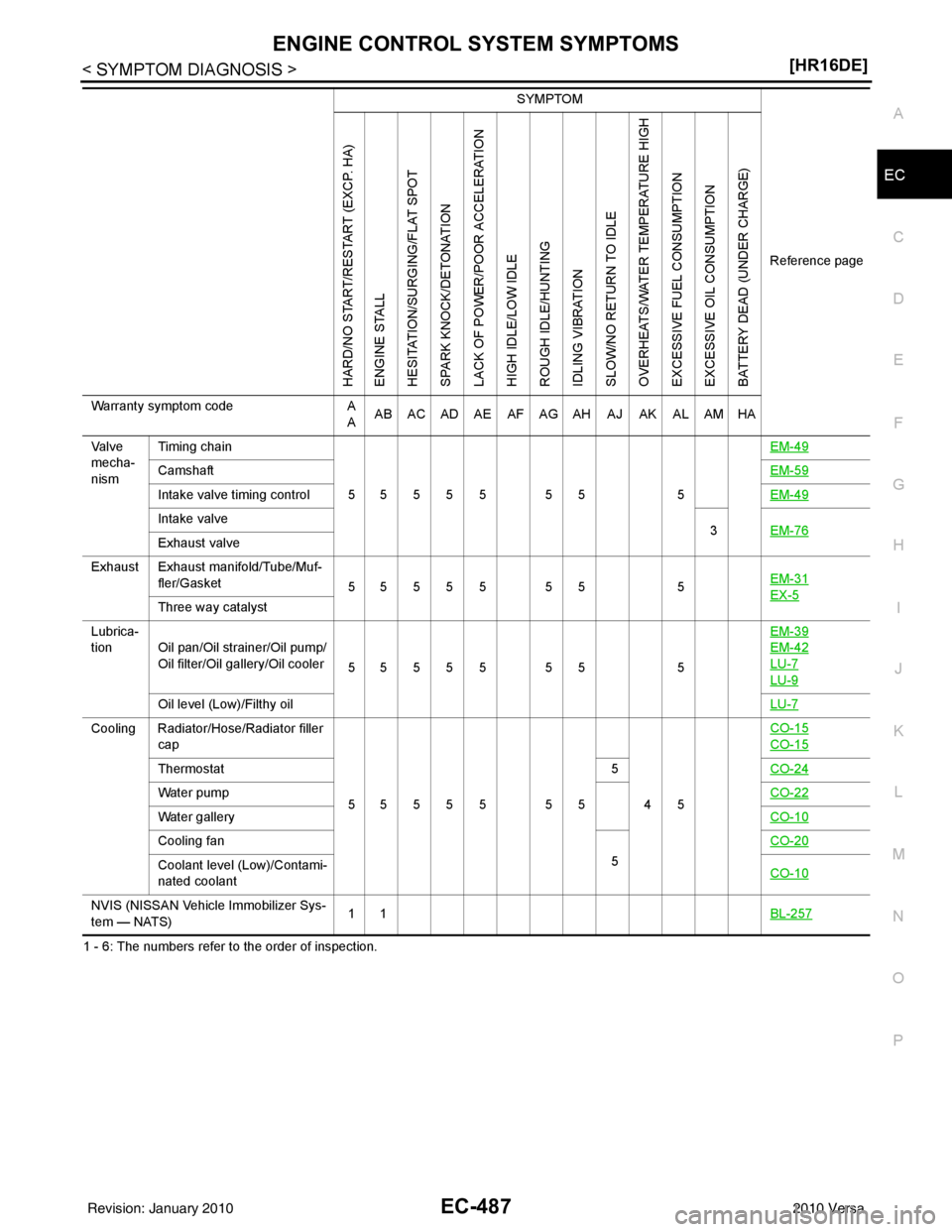
1 - 6: The numbers refer to the order of inspection. Va l v e
mecha-
nism
Timing chain
55555 55 5 EM-49
Camshaft
EM-59
Intake valve timing controlEM-49
Intake valve
3EM-76
Exhaust valve
Exhaust Exhaust manifold/Tube/Muf- fler/Gasket 55555 55 5 EM-31
EX-5Three way catalyst
Lubrica-
tion Oil pan/Oil strainer/Oil pump/ Oil filter/Oil gallery/Oil cooler 55555 55 5EM-39
EM-42
LU-7
LU-9
Oil level (Low)/Filthy oil
LU-7
Cooling Radiator/Hose/Radiator filler
cap
55555 55 45 CO-15
CO-15
Thermostat
5CO-24
Water pump CO-22
Water galleryCO-10
Cooling fan
5CO-20
Coolant level (Low)/Contami-
nated coolant
CO-10
NVIS (NISSAN Vehicle Immobilizer Sys-
tem — NATS)11
BL-257
SYMPTOM
Reference page
HARD/NO START/RESTART (EXCP. HA)
ENGINE STALL
HESITATION/SURGING/FLAT SPOT
SPARK KNOCK/DETONATION
LACK OF POWER/POOR ACCELERATION
HIGH IDLE/LOW IDLE
ROUGH IDLE/HUNTING
IDLING VIBRATION
SLOW/NO RETURN TO IDLE
OVERHEATS/WATER TEMPERATURE HIGH
EXCESSIVE FUEL CONSUMPTION
EXCESSIVE OIL CONSUMPTION
BATTERY DEAD (UNDER CHARGE)
Warranty symptom code A
A AB AC AD AE AF AG AH AJ AK AL AM HA
Revision: January 20102010 Versa
Page 1817 of 3745
EC-552
< SERVICE INFORMATION >[MR18DE]
ON BOARD DIAGNOSTIC (OBD) SYSTEM
• Sea level
• Flat road
• Ambient air temperature: 20 - 30
°C (68 - 86° F)
• Diagnosis is performed as quickly as possible under normal conditions.
Under different conditions [For example: ambient air temperature other than 20 - 30 °C (68 - 86 °F)], diagno-
sis may also be performed.
Pattern 1:
• The engine is started at the engine coolant temperature of −10 to 35 °C (14 to 95 °F)
(where the voltage between the ECM te rminal 38 and ground is 3.0 - 4.3 V).
• The engine must be operated at idle speed until the engine coolant temper ature is greater than 70°C
(158° F) (where the voltage between the ECM termi nal 38 and ground is lower than 1.4 V).
• The engine is started at the fuel tank temperature of warmer than 0° C (32°F) (where the voltage
between the ECM terminal 43 and ground is less than 4.1 V).
Pattern 2:
• When steady-state driving is performed again even after it is interrupted, each diagnosis can be conducted. In this case, the time required for diagnosis may be extended.
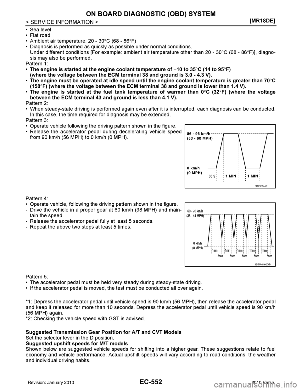
Pattern 3:
• Operate vehicle following the driving pattern shown in the figure.
• Release the accelerator pedal during decelerating vehicle speed from 90 km/h (56 MPH) to 0 km/h (0 MPH).
Pattern 4:
• Operate vehicle, following the driving pattern shown in the figure.
- Drive the vehicle in a proper gear at 60 km/h (38 MPH) and main- tain the speed.
- Release the accelerator pedal fully at least 5 seconds.
- Repeat the above two steps at least 5 times.
Pattern 5:
• The accelerator pedal must be held very steady during steady-state driving.
• If the accelerator pedal is moved, t he test must be conducted all over again.
*1: Depress the accelerator pedal until vehicle speed is 90 km/h (56 MPH), then release the accelerator pedal
and keep it released for more than 10 seconds. Depress the accelerator pedal until vehicle speed is 90 km/h
(56 MPH) again.
*2: Checking the vehicle speed with GST is advised.
Suggested Transmission Gear Po sition for A/T and CVT Models
Set the selector lever in the D position.
Suggested upshift speeds for M/T models
Shown below are suggested vehicle speeds for shifting into a higher gear. These suggestions relate to fuel
economy and vehicle performance. Actual upshift speeds will vary according to road conditions, the weather
and individual driving habits.
PBIB2244E
JSBIA0160GB
Revision: January 20102010 Versa
Page 1855 of 3745
EC-590
< SERVICE INFORMATION >[MR18DE]
TROUBLE DIAGNOSIS
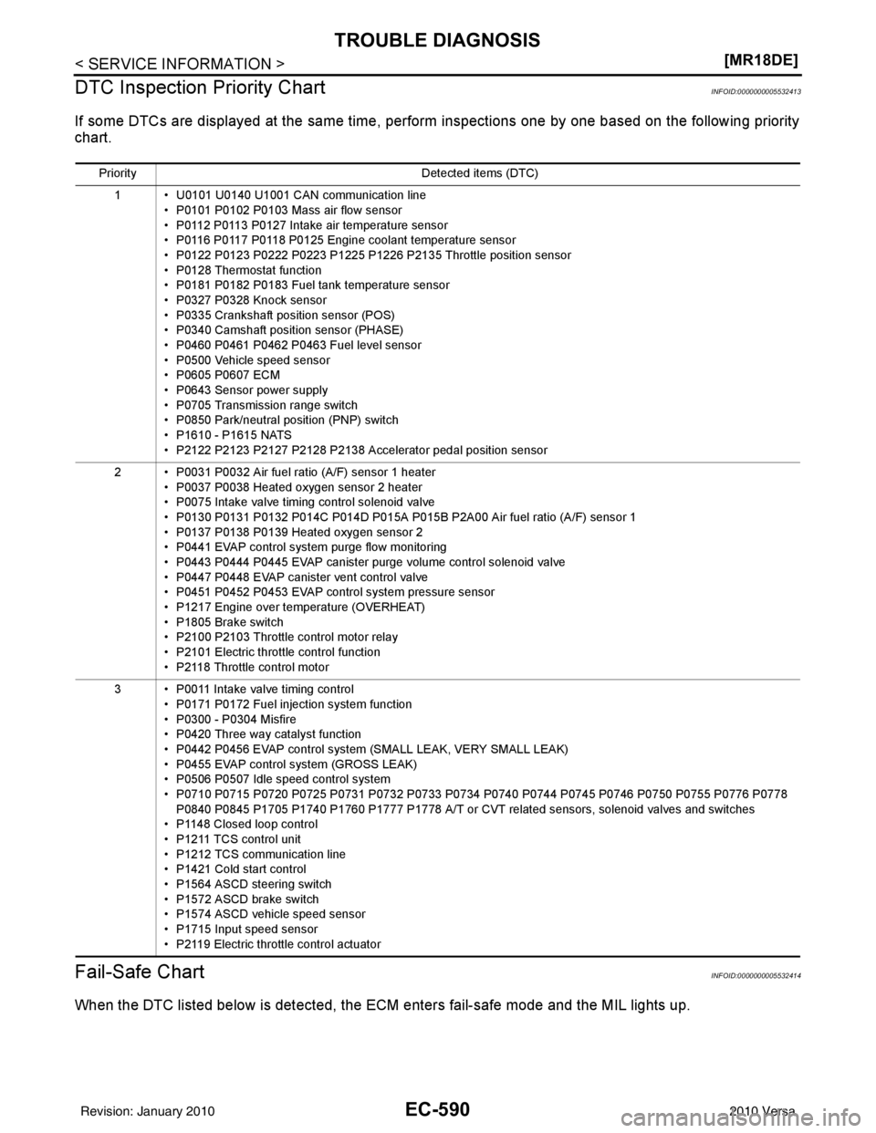
DTC Inspection Priority Chart
INFOID:0000000005532413
If some DTCs are displayed at the same time, perform inspections one by one based on the following priority
chart.
Fail-Safe ChartINFOID:0000000005532414
When the DTC listed below is detected, the ECM enters fail-safe mode and the MIL lights up.
Priority Detected items (DTC)
1 • U0101 U0140 U1001 CAN communication line • P0101 P0102 P0103 Mass air flow sensor
• P0112 P0113 P0127 Intake air temperature sensor
• P0116 P0117 P0118 P0125 Engine coolant temperature sensor
• P0122 P0123 P0222 P0223 P1225 P1226 P2135 Throttle position sensor
• P0128 Thermostat function
• P0181 P0182 P0183 Fuel tank temperature sensor
• P0327 P0328 Knock sensor
• P0335 Crankshaft position sensor (POS)
• P0340 Camshaft position sensor (PHASE)
• P0460 P0461 P0462 P0463 Fuel level sensor
• P0500 Vehicle speed sensor
• P0605 P0607 ECM
• P0643 Sensor power supply
• P0705 Transmission range switch
• P0850 Park/neutral position (PNP) switch
• P1610 - P1615 NATS
• P2122 P2123 P2127 P2128 P2138 Accelerator pedal position sensor
2 • P0031 P0032 Air fuel ratio (A/F) sensor 1 heater • P0037 P0038 Heated oxygen sensor 2 heater
• P0075 Intake valve timing control solenoid valve
• P0130 P0131 P0132 P014C P0 14D P015A P015B P2A00 Air fuel ratio (A/F) sensor 1
• P0137 P0138 P0139 Heated oxygen sensor 2
• P0441 EVAP control system purge flow monitoring
• P0443 P0444 P0445 EVAP canister purge volume control solenoid valve
• P0447 P0448 EVAP canister vent control valve
• P0451 P0452 P0453 EVAP control system pressure sensor
• P1217 Engine over temperature (OVERHEAT)
• P1805 Brake switch
• P2100 P2103 Throttle control motor relay
• P2101 Electric throttle control function
• P2118 Throttle control motor
3 • P0011 Intake valve timing control • P0171 P0172 Fuel injection system function
• P0300 - P0304 Misfire
• P0420 Three way catalyst function
• P0442 P0456 EVAP co ntrol system (SMALL LEAK, VERY SMALL LEAK)
• P0455 EVAP control system (GROSS LEAK)
• P0506 P0507 Idle speed control system
• P0710 P0715 P0720 P0725 P0731 P0732 P0733 P0734 P0740 P0744 P0745 P0746 P0750 P0755 P0776 P0778 P0840 P0845 P1705 P1740 P1760 P1777 P1778 A/T or CVT related sensors, solenoid valves and switches
• P1148 Closed loop control
• P1211 TCS control unit
• P1212 TCS communication line
• P1421 Cold start control
• P1564 ASCD steering switch
• P1572 ASCD brake switch
• P1574 ASCD vehicle speed sensor
• P1715 Input speed sensor
• P2119 Electric throttle control actuator
Revision: January 20102010 Versa
Page 1860 of 3745
TROUBLE DIAGNOSISEC-595
< SERVICE INFORMATION > [MR18DE]
C
D
E
F
G H
I
J
K L
M A
EC
NP
O
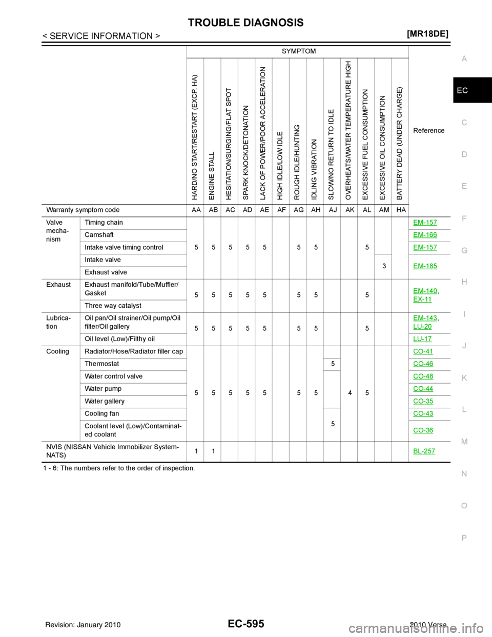
1 - 6: The numbers refer to the order of inspection. Va l v e
mecha-
nism
Timing chain
55555 55 5EM-157
Camshaft
EM-166
Intake valve timing controlEM-157
Intake valve
3EM-185
Exhaust valve
Exhaust Exhaust manifold/Tube/Muffler/ Gasket 55555 55 5EM-140
,
EX-11
Three way catalyst
Lubrica-
tion Oil pan/Oil strainer/Oil pump/Oil
filter/Oil gallery
55555 55 5EM-143
,
LU-20
Oil level (Low)/Filthy oil LU-17
Cooling Radiator/Hose/Radiator filler cap
55555 55 45 CO-41
Thermostat
5CO-46
Water control valve CO-48
Water pumpCO-44
Water galleryCO-35
Cooling fan
5CO-43
Coolant level (Low)/Contaminat-
ed coolant
CO-36
NVIS (NISSAN Vehicle
Immobilizer System-
NATS) 11
BL-257
SYMPTOM
Reference
HARD/NO START/RESTART (EXCP. HA)
ENGINE STALL
HESITATION/SURGING/FLAT SPOT
SPARK KNOCK/DETONATION
LACK OF POWER/POOR ACCELERATION
HIGH IDLE/LOW IDLE
ROUGH IDLE/HUNTING
IDLING VIBRATION
SLOW/NO RETURN TO IDLE
OVERHEATS/WATER TEMPERATURE HIGH
EXCESSIVE FUEL CONSUMPTION
EXCESSIVE OIL CONSUMPTION
BATTERY DEAD (UNDER CHARGE)
Warranty symptom code AA AB AC AD AE AF AG AH AJ AK AL AM HA
Revision: January 20102010 Versa
Page 1879 of 3745
EC-614
< SERVICE INFORMATION >[MR18DE]
TROUBLE DIAGNOSIS
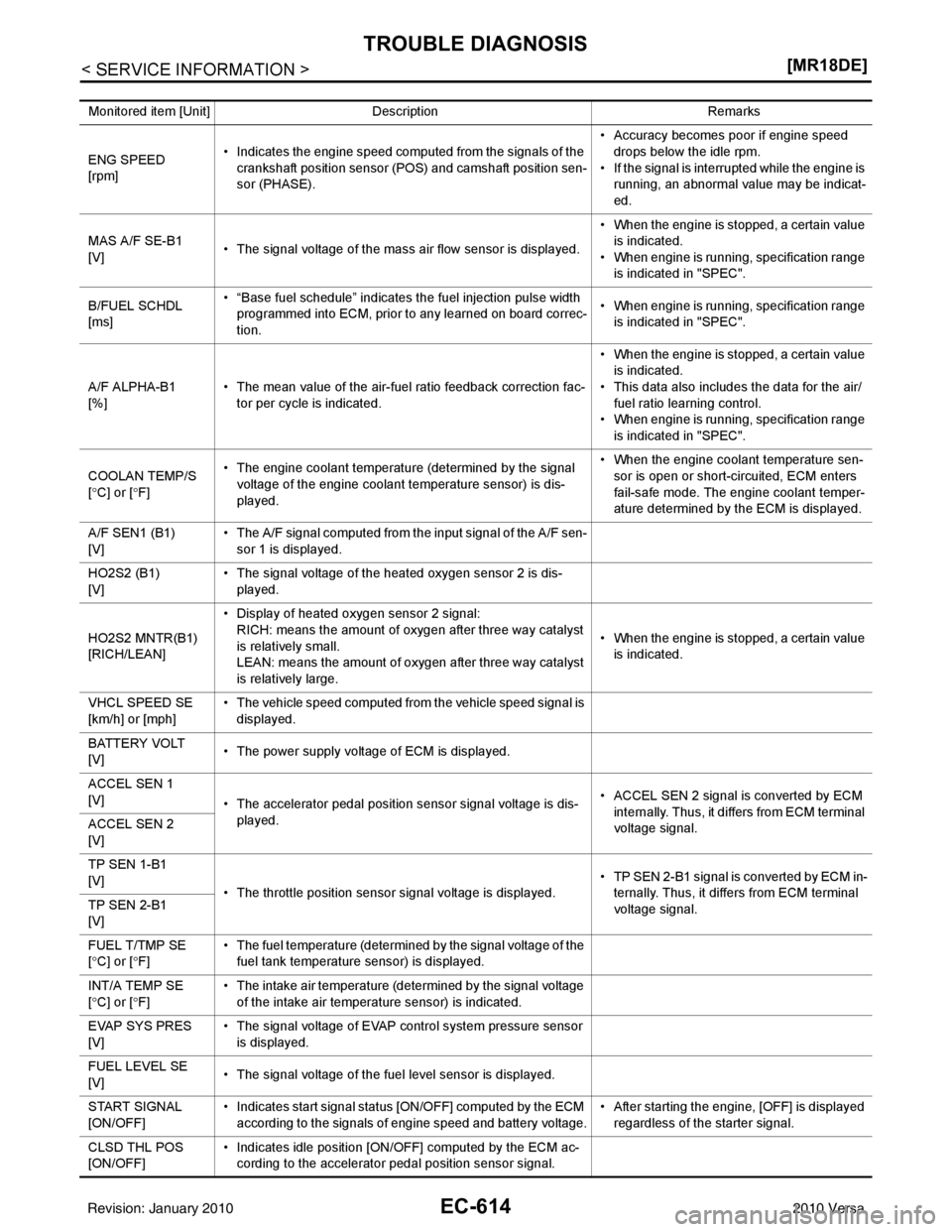
Monitored item [Unit]
Description Remarks
ENG SPEED
[rpm] • Indicates the engine speed computed from the signals of the
crankshaft position sensor (POS) and camshaft position sen-
sor (PHASE). • Accuracy becomes poor if engine speed
drops below the idle rpm.
• If the signal is interrupted while the engine is
running, an abnormal value may be indicat-
ed.
MAS A/F SE-B1
[V] • The signal voltage of the mass air flow sensor is displayed. • When the engine is stopped, a certain value
is indicated.
• When engine is running, specification range is indicated in "SPEC".
B/FUEL SCHDL
[ms] • “Base fuel schedule” indicates the fuel injection pulse width
programmed into ECM, prior to any learned on board correc-
tion. • When engine is running, specification range
is indicated in "SPEC".
A/F ALPHA-B1
[%] • The mean value of the air-fuel ratio feedback correction fac-
tor per cycle is indicated. • When the engine is stopped, a certain value
is indicated.
• This data also includes the data for the air/
fuel ratio learning control.
• When engine is running, specification range is indicated in "SPEC".
COOLAN TEMP/S
[ ° C] or [ °F] • The engine coolant temperature (determined by the signal
voltage of the engine coolant temperature sensor) is dis-
played. • When the engine coolant temperature sen-
sor is open or short-circuited, ECM enters
fail-safe mode. The engine coolant temper-
ature determined by the ECM is displayed.
A/F SEN1 (B1)
[V] • The A/F signal computed from the input signal of the A/F sen-
sor 1 is displayed.
HO2S2 (B1)
[V] • The signal voltage of the heated oxygen sensor 2 is dis-
played.
HO2S2 MNTR(B1)
[RICH/LEAN] • Display of heated oxygen sensor 2 signal:
RICH: means the amount of oxygen after three way catalyst
is relatively small.
LEAN: means the amount of oxygen after three way catalyst
is relatively large. • When the engine is stopped, a certain value
is indicated.
VHCL SPEED SE
[km/h] or [mph] • The vehicle speed computed from the vehicle speed signal is
displayed.
BATTERY VOLT
[V] • The power supply voltage of ECM is displayed.
ACCEL SEN 1
[V] • The accelerator pedal position sensor signal voltage is dis-
played. • ACCEL SEN 2 signal is converted by ECM
internally. Thus, it differs from ECM terminal
voltage signal.
ACCEL SEN 2
[V]
TP SEN 1-B1
[V]
• The throttle position sensor signal voltage is displayed. • TP SEN 2-B1 signal is converted by ECM in-
ternally. Thus, it differs from ECM terminal
voltage signal.
TP SEN 2-B1
[V]
FUEL T/TMP SE
[
° C] or [ °F] • The fuel temperature (determined by the signal voltage of the
fuel tank temperature sensor) is displayed.
INT/A TEMP SE
[ ° C] or [ °F] • The intake air temperature (determined by the signal voltage
of the intake air temperature sensor) is indicated.
EVAP SYS PRES
[V ] •
The signal voltage of EVAP control system pressure sensor
is displayed.
FUEL LEVEL SE
[V] • The signal voltage of the fuel level sensor is displayed.
START SIGNAL
[ON/OFF] • Indicates start signal status [ON/OFF] computed by the ECM
according to the signals of engine speed and battery voltage. • After starting the engine, [OFF] is displayed
regardless of the starter signal.
CLSD THL POS
[ON/OFF] • Indicates idle position [ON/OFF] computed by the ECM ac-
cording to the accelerator pedal position sensor signal.
Revision: January 20102010 Versa
Page 1948 of 3745
DTC P0116 ECT SENSOREC-683
< SERVICE INFORMATION > [MR18DE]
C
D
E
F
G H
I
J
K L
M A
EC
NP
O
DTC P0116 ECT SENSOR
Component DescriptionINFOID:0000000005532503
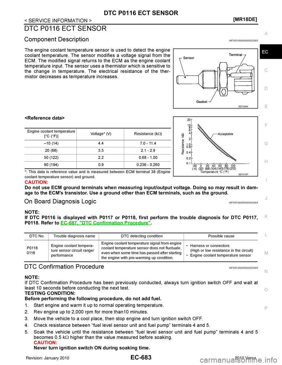
The engine coolant temperature sensor is used to detect the engine
coolant temperature. The sensor
modifies a voltage signal from the
ECM. The modified signal returns to the ECM as the engine coolant
temperature input. The sensor uses a thermistor which is sensitive to
the change in temperature. The electrical resistance of the ther-
mistor decreases as temperature increases.
*: This data is reference value and is measured between ECM terminal 38 (Engine
coolant temperature sensor) and ground.
CAUTION:
Do not use ECM ground terminals wh en measuring input/output voltage. Doing so may result in dam-
age to the ECM's transistor. Use a ground ot her than ECM terminals, such as the ground.
On Board Diagnosis LogicINFOID:0000000005532504
NOTE:
If DTC P0116 is displayed with P0117 or P0118, first perform the trouble diagnosis for DTC P0117,
P0118. Refer to EC-687, "
DTC Confirmation Procedure".
DTC Confirmation ProcedureINFOID:0000000005532505
NOTE:
If DTC Confirmation Procedure has been previously conducted, always turn ignition switch OFF and wait at
least 10 seconds before conducting the next test.
TESTING CONDITION:
Before performing the following procedure, do not add fuel.
1. Start engine and warm it up to normal operating temperature.
2. Rev engine up to 2,000 rpm for more than10 minutes.
3. Move the vehicle to a cool place, then stop engine and turn ignition switch OFF.
4. Check resistance between “fuel level s ensor unit and fuel pump” terminals 4 and 5.
5. Soak the vehicle until the resistance between “fuel level sensor unit and fuel pump” terminals 4 and 5
becomes 0.5 kΩ higher than the value measured before soaking.
CAUTION:
Never turn ignition switch ON during soaking time.
SEF594K
Engine coolant temperature
[° C ( °F)] Voltage* (V)
Resistance (kΩ)
–10 (14) 4.47.0 - 11.4
20 (68) 3.52.1 - 2.9
50 (122) 2.20.68 - 1.00
90 (194) 0.90.236 - 0.260
SEF012P
DTC No. Trouble diagnosis name DTC detecting conditionPossible cause
P0116
0116 Engine coolant tempera-
ture sensor circuit range/
performance Engine coolant temperature signal from engine
coolant temperature sensor does not fluctuate,
even when some time has passed after starting
the engine with pre-warming up condition. • Harness or connectors
(High or low resistance in the circuit)
• Engine coolant temperature sensor
Revision: January 20102010 Versa
Page 2035 of 3745
EC-770
< SERVICE INFORMATION >[MR18DE]
DTC P0181 FTT SENSOR
DTC P0181 FTT SENSOR
Component DescriptionINFOID:0000000005532605
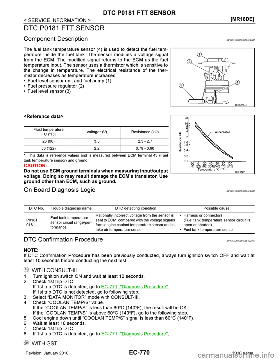
The fuel tank temperature sensor
(4) is used to detect the fuel tem-
perature inside the fuel tank. The sensor modifies a voltage signal
from the ECM. The modified signal returns to the ECM as the fuel
temperature input. The sensor uses a thermistor which is sensitive to
the change in temperature. The elec trical resistance of the ther-
mistor decreases as temperature increases.
• Fuel level sensor unit and fuel pump (1)
• Fuel pressure regulator (2)
• Fuel level sensor (3)
*: This data is reference values and is measured between ECM terminal 43 (Fuel
tank temperature sensor) and ground.
CAUTION:
Do not use ECM ground terminals when measuring input/output
voltage. Doing so may result da mage the ECM's transistor. Use
ground other than ECM, such as ground.
On Board Diagn osis LogicINFOID:0000000005532606
DTC Confirmation ProcedureINFOID:0000000005532607
NOTE:
If DTC Confirmation Procedure has been previously conducted, always turn ignition switch OFF and wait at
least 10 seconds before conducting the next test.
WITH CONSULT-III
1. Turn ignition switch ON and wait at least 10 seconds.
2. Check 1st trip DTC.
If 1st trip DTC is detected, go to EC-771, "
Diagnosis Procedure".
If 1st trip DTC is not detected, go to following step.
3. Select “DATA MONITOR” mode with CONSULT-III.
4. Check “COOLAN TEMP/S” value. If the “COOLAN TEMP/S” is less than 60 °C (140° F), the result will be OK.
If the “COOLAN TEMP/S” is above 60 °C (140° F), go to the following step.
5. Cool engine down until “COOLAN TEMP/S” signal is less than 60 °C (140° F).
6. Wait at least 10 seconds.
7. Check 1st trip DTC.
8. If 1st trip DTC is detected, go to EC-771, "
Diagnosis Procedure".
WITH GST
BBIA0704E
Fluid temperature
[° C ( °F)] Voltage* (V)
Resistance (kΩ)
20 (68) 3.52.3 - 2.7
50 (122) 2.20.79 - 0.90
SEF012P
DTC No. Trouble diagnosis name DTC detecting condition Possible cause
P0181
0181 Fuel tank temperature
sensor circuit range/per-
formance Rationally incorrect voltage from the sensor is
sent to ECM, compared with the voltage signals
from engine coolant temperature sensor and in-
take air temperature sensor. • Harness or connectors
(Fuel tank temperature sensor circuit is
open or shorted)
• Fuel tank temperature sensor
Revision: January 20102010 Versa
Page 2088 of 3745
DTC P0443 EVAP CANISTER PURGE VOLUME CONTROL SOLENOID VALVE
EC-823
< SERVICE INFORMATION > [MR18DE]
C
D
E
F
G H
I
J
K L
M A
EC
NP
O
On Board Diagnosis LogicINFOID:0000000005532669
DTC Confirmation ProcedureINFOID:0000000005532670
Perform PROCEDURE FOR MALFUNCTION A first.
If the DTC cannot be confirmed,
perform PROCEDURE FOR MALFUNCTION B.
NOTE:
If DTC Confirmation Procedure has been previously conducted, always turn ignition switch OFF and wait at
least 10 seconds before conducting the next test.
PROCEDURE FOR MALFUNCTION A
TESTING CONDITION:
• Perform "DTC Confirmation Procedure" when the fuel le vel is between 1/4 and 3/4 full, and vehicle is placed
on flat level surface.
• Always perform test at a temperature of 5 to 60° C (41 to 140°F).
• Cool the vehicle so that engine coolant temperat ure becomes same level as ambient temperature.
With CONSULT-III
1. Turn ignition switch ON and select "DATA MONITOR" mode with CONSULT-III.
2. Check that the following condition are met.
FUEL T/TMP SE: 0 – 35 °C (32 – 95° F)
3. Start engine and wait at least 60 seconds.
4. Check 1st trip DTC.
5. If 1st trip DTC is detected, go to EC-826, "
Diagnosis Procedure".
With GST
1. Turn ignition switch ON.
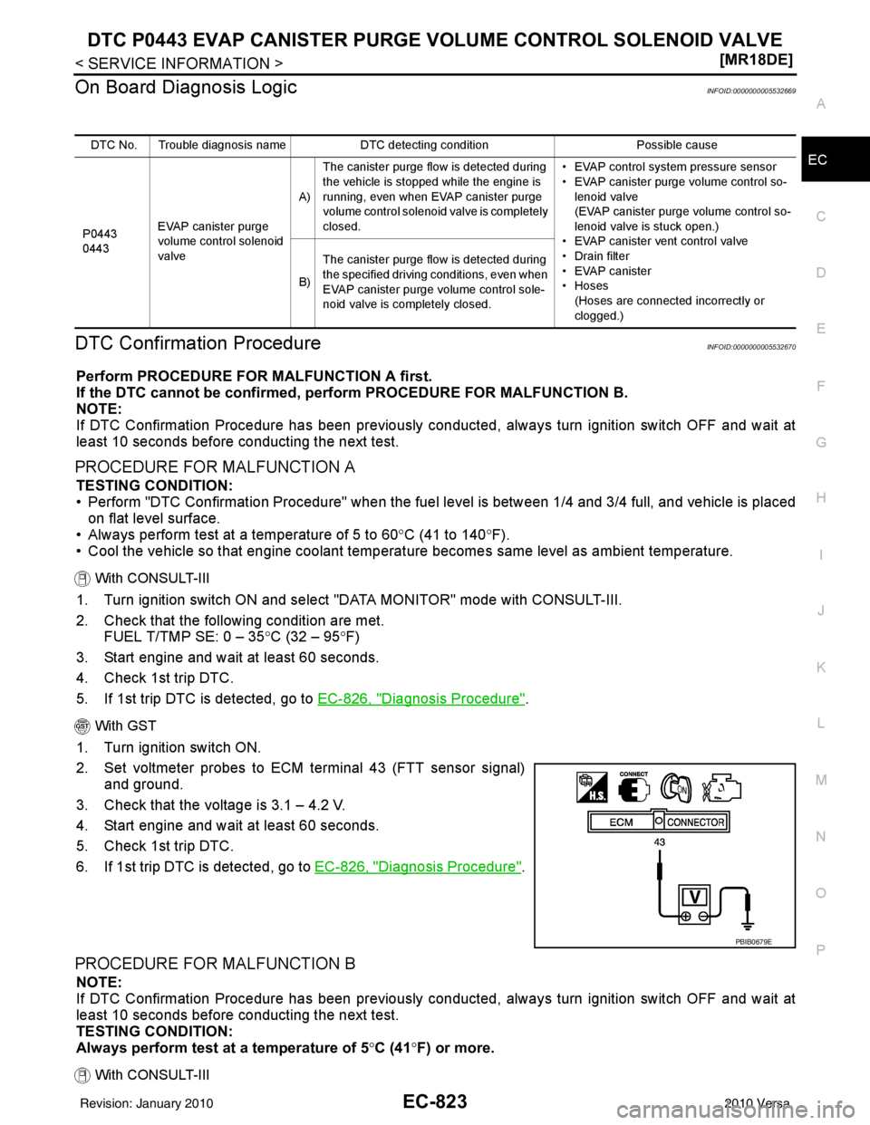
2. Set voltmeter probes to ECM terminal 43 (FTT sensor signal)
and ground.
3. Check that the voltage is 3.1 – 4.2 V.
4. Start engine and wait at least 60 seconds.
5. Check 1st trip DTC.
6. If 1st trip DTC is detected, go to EC-826, "
Diagnosis Procedure".
PROCEDURE FOR MALFUNCTION B
NOTE:
If DTC Confirmation Procedure has been previously conducted, always turn ignition switch OFF and wait at
least 10 seconds before conducting the next test.
TESTING CONDITION:
Always perform test at a temperature of 5 °C (41° F) or more.
With CONSULT-III
DTC No. Trouble diagnosis name DTC detecting condition Possible cause
P0443
0443 EVAP canister purge
volume control solenoid
valve A)
The canister purge flow is detected during
the vehicle is stopped while the engine is
running, even when EVAP canister purge
volume control solenoid valve is completely
closed. • EVAP control system pressure sensor
• EVAP canister purge volume control so-
lenoid valve
(EVAP canister purge volume control so-
lenoid valve is stuck open.)
• EVAP canister vent control valve
• Drain filter
• EVAP canister
• Hoses (Hoses are connected incorrectly or
clogged.)
B)
The canister purge flow is detected during
the specified driving conditions, even when
EVAP canister purge volume control sole-
noid valve is completely closed.
PBIB0679E
Revision: January 20102010 Versa