Oil light NISSAN TIIDA 2010 Service Owner's Guide
[x] Cancel search | Manufacturer: NISSAN, Model Year: 2010, Model line: TIIDA, Model: NISSAN TIIDA 2010Pages: 3745, PDF Size: 73.67 MB
Page 2545 of 3745

EM-186
< SERVICE INFORMATION >[MR18DE]
CYLINDER HEAD
3. Install valve oil seal.
• Install with a valve oil seal using Tool (A) to match dimensionas shown.
NOTE:
Dimension (H) is height that measured before installing valve
spring (with valve spring seat).
4. Install valve. • Install larger diameter to intake side.
5. Install valve spring (with valve spring seat). • Install smaller pitch (valve spring seat side) to cylinder headside (B).
• Confirm identification color (A) of valve spring.
6. Install valve spring retainer.
7. Install valve collet. • Compress valve spring using Tool, attachment and adapter (A). Install valve collet with a magnet hand.
CAUTION:
When working, be careful not to damage valve lifter holes.
• Tap valve stem edge lightly with a plastic hammer after instal- lation to check its installed condition.
8. Install valve lifter. • Install it in the original position.
9. Install spark plug using suitable tool.
Inspection After DisassemblyINFOID:0000000005398142
VALVE DIMENSIONS
• Check dimensions of each valve. For dimensions, refer to EM-223, "Standard and Limit".
• If dimensions are out of the standard, replace valve.
VALVE GUIDE CLEARANCE
Valve Stem Diameter
Tool number : KV10115600 (J-38958)
Height (H) : 15.1 - 15.7 mm (0.594 - 0.618 in)
PBIC3211J
1 : Valve spring seat (Do not remove from valve spring.)
Intake : White
Exhaust : Orange
PBIC3462J
Tool number : KV101092S0 (J-26336 B)
PBIC3209J
Revision: January 20102010 Versa
Page 2553 of 3745

EM-194
< SERVICE INFORMATION >[MR18DE]
ENGINE ASSEMBLY
• Do not allow engine oil to get on engine mounting insulator. Be careful not to damage engine mounting insu-
lator.
• When installation directions are specified, install parts according to the directions. Refer to EM-191, "
Com-
ponent".
• Prior to installing the upper torque rod, apply a light coat of silicone lubricant (A) to the washer facing side of the bushing inner tube as
shown.
NOTE:
• Apply silicone lubricant (A) by dabbing the outward facing tube
surface with a sponge or suitable tool.
• Do not apply excess lubricant.
• Make sure that each mounting insulator is seated properly, and tighten nuts and bolts.
• Tighten engine mounting insulator (RH) bolts in the numerical order shown.
INSPECTION AFTER INSTALLATION
Inspection for Leaks
The following are procedures for checking fluids leak, lubricates leak and exhaust gases leak.• Before starting engine, check oil/fluid levels incl uding engine coolant and engine oil. If less than required
quantity, fill to the specified level. Refer to MA-14
.
• Use procedure below to check for fuel leakage.
- Turn ignition switch “ON” (with engine stopped). With fuel pressure applied to fuel piping, check for fuel leak-
age at connection points.
- Start engine. With engine speed increased, che ck again for fuel leakage at connection points.
• Run engine to check for unusual noise and vibration.
• Warm up engine thoroughly to make sure there is no leakage of fuel, exhaust gases, or any oil/fluids includ- ing engine oil and engine coolant.
• Bleed air from lines and hoses of applicable lines, such as in cooling system.
• After cooling down engine, again check oil/fluid levels including engine oil and engine coolant. Refill to the specified level, if necessary.
Summary of the inspection items:
* Transmission/transaxle/CVT fluid, power steering fluid, brake fluid, etc. : Vehicle front
LBIA0470E
: Vehicle front
WBIA0785E
Item
Before starting engine Engine runningAfter engine stopped
Engine coolant LevelLeakage Level
Engine oil LevelLeakage Level
Other oils and fluid* LevelLeakage Level
Fuel LeakageLeakageLeakage
Exhaust gases —Leakage —
Revision: January 20102010 Versa
Page 2578 of 3745

CYLINDER BLOCKEM-219
< SERVICE INFORMATION > [MR18DE]
C
D
E
F
G H
I
J
K L
M A
EM
NP
O
• Install connecting rod bearings (2) to connecting rod (3) and con-
necting rod bearing cap (1), and tighten connecting rod bolts to the
specified torque. Refer to EM-196, "
Disassembly and Assembly"
for tightening procedure.
• Measure the inner diameter of connecting rod bearing with an inside micrometer.
(Bearing oil clearance) = (Connecting rod bearing inner diameter)
– (Crankshaft pin journal diameter)
• If clearance exceeds the limit, select proper connecting rod bearing according to connecting rod big end diameter and crankshaft pin journal diameter to obtain specified bearing oil clearance. Refer to EM-205,
"How to Select Piston and Bearing".
Method of Using Plastigage
• Remove engine oil and dust on crankshaft pin and the surfaces of each bearing completely.
• Cut a plastigage slightly shorter than the bearing width, and place it in crankshaft axial direction, avoiding oil
holes.
• Install connecting rod bearings to connecting rod and c ap, and tighten connecting rod bolts to the specified
torque. Refer to EM-196, "
Disassembly and Assembly" for the tightening procedure.
CAUTION:
Never rotate crankshaft.
• Remove connecting rod cap and bearing, and using the scale (A) on the plastigage bag, measure the plastigage width.
NOTE:
The procedure when the measured value exceeds the limit is
same as that described in the “Method by Calculation”.
MAIN BEARING OIL CLEARANCE
Method by Calculation
• Install main bearings (3) to cylinder block (1) and main bearing cap(2), and tighten main bearing cap bolts to the specified torque.
Refer to EM-196, "
Disassembly and Assembly" for the tightening
procedure.
• Measure the inner diameter of main bearing with a bore gauge.
(Bearing oil clearance) = (Main bearing inner diameter) – (Crank-
shaft main journal diameter)
A : Example
B : Inner diameter measuring direction
Standard : 0.037 - 0.047 mm (0.0015 - 0.0019 in)
Limit : 0.07 mm (0.0028 in)
PBIC3275J
PBIC3276J
A : Example
B : Inner diameter measuring direction
Standard: No. 1, 4 and 5 journals : 0.024 - 0.034 mm (0.0009 - 0.0013 in)
No. 2 and 3 journals : 0.012 - 0.022 mm (0.0005 - 0.0009 in)
Limit : 0.065 mm (0.0026 in)
PBIC3277J
Revision: January 20102010 Versa
Page 2579 of 3745

EM-220
< SERVICE INFORMATION >[MR18DE]
CYLINDER BLOCK
• If clearance exceeds the limit, select proper main
bearing according to main bearing inner diameter and
crankshaft main journal diameter to obtain specified bearing oil clearance. Refer to EM-205, "
How to Select
Piston and Bearing".
Method of Using Plastigage
• Remove engine oil and dust on crankshaft main journal and the surfaces of each bearing completely.
• Cut a plastigage slightly shorter than the bearing width, and place it in crankshaft axial direction, avoiding oil
holes.
• Install main bearings to cylinder block and main bearing cap, and tighten main bearing cap bolts to the spec- ified torque. Refer to EM-196, "
Disassembly and Assembly" for the tightening procedure.
CAUTION:
Never rotate crankshaft.
• Remove main bearing cap and bearings, and using the scale (A) on the plastigage bag, measure the plastigage width.
NOTE:
The procedure when the measured value exceeds the limit is
same as that described in the “Method by Calculation”.
MAIN BEARING CRUSH HEIGHT
• When main bearing cap is removed after being tightened to thespecified torque with main bearings (1) installed, the tip end of
bearing must protrude (B). Refer to EM-196, "
Disassembly and
Assembly" for the tightening procedure.
• If the standard is not met, replace main bearings.
CONNECTING ROD BEARING CRUSH HEIGHT
• When connecting rod bearing cap is removed after being tightened to the specified torque with connecting rod bearings (1) installed,
the tip end of bearing must protrude. Refer to EM-196, "
Disassem-
bly and Assembly" for the tightening procedure (B).
• If the standard is not met, replace connecting rod bearings.
MAIN BEARING CAP BOLT OUTER DIAMETER
PBIC3278J
A : Example
Standard : There must be crush height.
PBIC3279J
A : Example
Standard : There must be crush height.
PBIC3279J
Revision: January 20102010 Versa
Page 3001 of 3745
LT-6
< SERVICE INFORMATION >
HEADLAMP (FOR USA)
HEADLAMP (FOR USA)
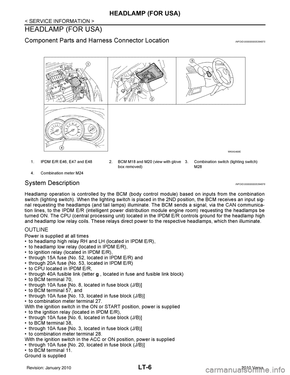
Component Parts and Harness Connector LocationINFOID:0000000005394875
System DescriptionINFOID:0000000005394876
Headlamp operation is controlled by the BCM (body c ontrol module) based on inputs from the combination
switch (lighting switch). When the lighting switch is pl aced in the 2ND position, the BCM receives an input sig-
nal requesting the headlamps (and tail lamps) illuminate. The BCM sends a signal, via the CAN communica-
tion lines, to the IPDM E/R (intelligent power di stribution module engine room) requesting the headlamps be
turned ON. The CPU (central processing unit) located in the IPDM E/R controls ground for the headlamp high
and headlamp low relay coils. These relays direct power to the respective headlamps, which then illuminate.
OUTLINE
Power is supplied at all times
• to headlamp high relay RH and LH (located in IPDM E/R),
• to headlamp low relay (located in IPDM E/R),
• to ignition relay (located in IPDM E/R),
• through 15A fuse (No. 52, located in IPDM E/R) and
• through 20A fuse (No. 53, located in IPDM E/R)
• to CPU located in IPDM E/R,
• through 40A fusible link (letter g , located in fuse and fusible link block)
• to BCM terminal 70,
• through 10A fuse [No. 8, located in fuse block (J/B)]
• to BCM terminal 57, and
• through 10A fuse [No. 13, located in fuse block (J/B)]
• to combination meter terminal 27.
With the ignition switch in the ON or START position, power is supplied
• to the ignition relay (located in IPDM E/R),
• through 10A fuse [No. 6, located in fuse block (J/B)]
• to BCM terminal 38,
• through 10A fuse [No. 3, located in fuse block (J/B)]
• to combination meter terminal 28.
With the ignition switch in the ACC or ON position, power is supplied
• through 10A fuse [No. 20, located in fuse block (J/B)]
• to BCM terminal 11.
Ground is supplied
1. IPDM E/R E46, E47 and E48 2. BCM M18 and M20 (view with glove
box removed)3. Combination switch (lighting switch)
M28
4. Combination meter M24
WKIA5469E
Revision: January 20102010 Versa
Page 3002 of 3745

HEADLAMP (FOR USA)LT-7
< SERVICE INFORMATION >
C
DE
F
G H
I
J
L
M A
B
LT
N
O P
• to BCM terminal 67
• to combination meter terminals 21, 22 and 23
• through grounds M57 and M61, and
• to IPDM E/R terminals 39 and 59
• through grounds E15 and E24.
HEADLAMP OPERATION
Low Beam Operation
With the lighting switch in 2ND position, the BCM re ceives an input signal requesting the headlamps to illumi-
nate. The BCM then sends a signal, via the CAN comm unication lines, to the IPDM E/R requesting the low
beam headlamps be turned ON. The CPU located in the IPDM E/R controls ground to the headlamp low relay
coil, which when energized, directs power
• through 15A fuse (No. 41, located in IPDM E/R)
• through IPDM E/R terminal 54
• to headlamp RH terminal 3, and
• through 15A fuse (No. 40, located in IPDM E/R)
• through IPDM E/R terminal 52
• to headlamp LH terminal 3.
Ground is supplied
• to headlamp RH and LH terminals 2
• through grounds E15 and E24.
With power and ground supplied, low beam headlamps illuminate.
High Beam Operation/Flash-to-Pass Operation
With the lighting switch in 2ND position and high beam switch in the HIGH position, the BCM receives an input
signal requesting the headlamp high beams to illuminate. The flash to pass feature can be used any time and
also sends a signal to the BCM. This input signal is then communicated to the IPDM E/R and the combination
meter via the CAN communication. The CPU located in the IPDM E/R controls the headlamp high relays (LH
and RH), which when energized, directs power
• through 10A fuse (No. 34, located in IPDM E/R)
• through IPDM E/R terminal 56
• to headlamp RH terminal 1, and
• through 10A fuse (No. 35, located in IPDM E/R)
• through IPDM E/R terminal 55
• to headlamp LH terminal 1.
Ground is supplied
• to headlamp RH and LH terminal 2
• through grounds E15 and E24.
With power and ground supplied, the high beam headlamps illuminate.
The BCM sends a signal, via the CAN communication lines, to the combination meter requesting the high
beam indicator lamp be turned ON.
COMBINATION SWITCH READING FUNCTION
Refer to BCS-4, "System Description" .
EXTERIOR LAMP BATTERY SAVER CONTROL
Refer to LT-75, "System Description" .
CAN COMMUNICATION SYSTEM DESCRIPTIONINFOID:0000000005394877
Refer to LAN-7 .
Revision: January 20102010 Versa
Page 3019 of 3745
LT-24
< SERVICE INFORMATION >
HEADLAMP (FOR USA)
Aiming Adjustment
INFOID:0000000005394892
PREPARATION BEFORE ADJUSTING
Before performing aiming adjustment, check the following.
1. Keep all tires inflated to correct pressures.
2. Place vehicle on level surface.
3. See that there is no-load in vehicle other than the driver (or equivalent weight placed in driver's position). Coolant, engine oil filled up to correct level and full fuel tank, spare tire, jack and tools are properly
stowed.
LOW BEAM AND HIGH BEAM
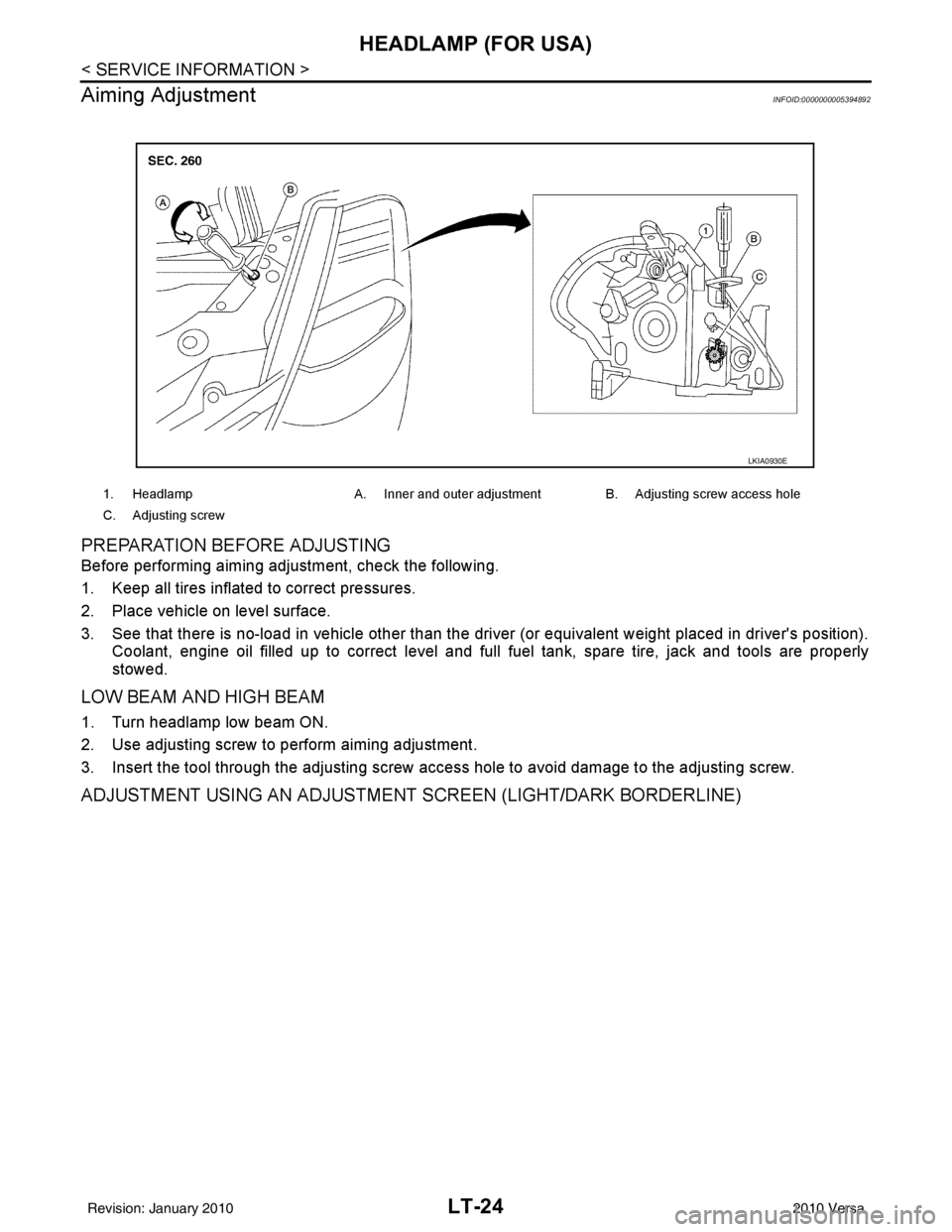
1. Turn headlamp low beam ON.
2. Use adjusting screw to perform aiming adjustment.
3. Insert the tool through the adjusting screw access hole to avoid damage to the adjusting screw.
ADJUSTMENT USING AN ADJUSTMENT SCREEN (LIGHT/DARK BORDERLINE)
1. Headlamp A. Inner and outer adjustment B. Adjusting screw access hole
C. Adjusting screw
LKIA0930E
Revision: January 20102010 Versa
Page 3023 of 3745
LT-28
< SERVICE INFORMATION >
HEADLAMP (FOR CANADA) - DAYTIME LIGHT SYSTEM -
HEADLAMP (FOR CANADA) - DAYTIME LIGHT SYSTEM -
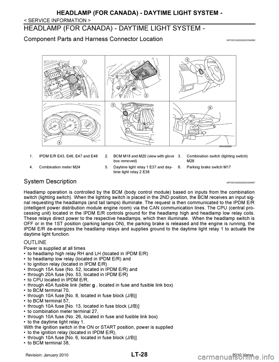
Component Parts and Harness Connector LocationINFOID:0000000005394896
System DescriptionINFOID:0000000005394897
Headlamp operation is controlled by the BCM (body c ontrol module) based on inputs from the combination
switch (lighting switch). When the lighting switch is pl aced in the 2ND position, the BCM receives an input sig-
nal requesting the headlamps (and tail lamps) illuminate. The request is then communicated to the IPDM E/R
(intelligent power distribution module engine room) vi a the CAN communication lines. The CPU (central pro-
cessing unit) located in the IPDM E/R controls ground for the headlamp high and headlamp low relay coils.
These relays direct power to the respective headlamps , which then illuminate. When the headlamp switch is
OFF or in the 1ST position (parking lamps ON), the parking brake is released and the engine is running, the
IPDM E/R de-energizes the headlamp relays and supplies ground to the daytime light relay 1 to actuate the
daytime light function.
OUTLINE
Power is supplied at all times
• to headlamp high relay RH and LH (located in IPDM E/R)
• to headlamp low relay (located in IPDM E/R) and
• to ignition relay (located in IPDM E/R)
• through 15A fuse (No. 52, located in IPDM E/R) and
• through 20A fuse (No. 53, located in IPDM E/R)
• to CPU located in IPDM E/R,
• through 40A fusible link (letter g , located in fuse and fusible link box)
• to BCM terminal 70,
• through 10A fuse [No. 8, located in fuse block (J/B)]
• to BCM terminal 57,
• through 10A fuse [No. 13, located in fuse block (J/B)]
• to combination meter terminal 27,
• through 10A fuse (No. 26, located in fuse and fusible link box)
• to the daytime light relay 1.
With the ignition switch in the ON or START position, power is supplied
• to the ignition relay (located in IPDM E/R),
• through 10A fuse [No. 6, located in fuse block (J/B)]
• to BCM terminal 38,
1. IPDM E/R E43, E46, E47 and E48 2. BCM M18 and M20 (view with glove
box removed)3. Combination switch (lighting switch)
M28
4. Combination meter M24 5. Daytime light relay 1 E37 and day-
time light relay 2 E38 6. Parking brake switch M17
WKIA5555E
Revision: January 20102010 Versa
Page 3024 of 3745

HEADLAMP (FOR CANADA) - DAYTIME LIGHT SYSTEM -
LT-29
< SERVICE INFORMATION >
C
D E
F
G H
I
J
L
M A
B
LT
N
O P
• through 10A fuse [No. 3, located in fuse block (J/B)]
• to combination meter terminal 28.
With the ignition switch in the ACC or ON position, power is supplied
• through 10A fuse [No. 20, located in fuse block (J/B)]
• to BCM terminal 11.
Ground is supplied
• to BCM terminal 67 and
• to combination meter terminals 21, 22 and 23
• through grounds M57 and M61,
• to IPDM E/R terminals 39 and 59
• through grounds E15 and E24,
HEADLAMP OPERATION
Low Beam Operation
With the lighting switch in 2ND position, the BCM re ceives an input signal requesting the headlamps to illumi-
nate. This input signal is communicated to the IPDM E/R via the CAN communication lines. The CPU located
in the IPDM E/R controls the headlamp low relay coil, which when energized, directs power
• through 15A fuse (No. 41, located in IPDM E/R)
• through IPDM E/R terminal 54
• to daytime light relay 2 terminals 1 and 5 (energizing the relay),
• through daytime light relay 2 terminal 3
• to front combination lamp RH terminal 3, and
• through 15A fuse (No. 40, located in IPDM E/R)
• through IPDM E/R terminal 52
• to front combination lamp LH terminal 3.
Ground is supplied
• to front combination lamp LH terminal 2
• through grounds E15 and E24,
• to headlamp RH terminal 2 via
• daytime light relay 1 terminals 3 and 4
• through grounds E15 and E24.
With power and ground supplied, low beam headlamps illuminate.
High Beam/Flash-to-Pass Operation
With the lighting switch in 2ND position and high beam s witch in the HIGH position, the BCM receives input
signal requesting the headlamp high beams to illuminate. The flash-to-pass feature can be used any time and
also sends a signal to the BCM. This input signal is communicated to the IPDM E/R and the combination
meter via the CAN communication lines. The CPU locat ed in the IPDM E/R controls the headlamp high relay
coil, which when energized, directs power
• through 10A fuse (No. 34, located in IPDM E/R)
• through IPDM E/R terminal 56
• to front combination lamp RH terminal 1, and
• through 10A fuse (No. 35, located in IPDM E/R)
• through IPDM E/R terminal 55
• to front combination lamp LH terminal 1.
Ground is supplied
• to front combination lamp LH terminal 2
• through grounds E15 and E24, and
• to front combination lamp RH terminal 2 via
• daytime light relay 1 terminals 3 and 4
• through grounds E15 and E24.
With power and ground supplied, the high beam headlamps illuminate.
The BCM sends a signal to the combination meter requesting the high beam indicator lamp to turn ON.
Daytime Light System Operation
With the lighting switch in the OFF or 1ST position (parking lamps ON), the BCM receives inputs requesting
the headlights off. If the parking brake is released and the engine is running, the BCM then sends a signal, via
the CAN communication lines, requesting the IPDM E/R to activate the daytime light system. The CPU located
in the IPDM E/R controls the daytime light relay 1 coil, which when energized, directs power
• from daytime light relay 1 terminal 3
• to front combination lamp RH terminal 2,
• through front combination lamp RH high beam terminal 1
Revision: January 20102010 Versa
Page 3033 of 3745
LT-38
< SERVICE INFORMATION >
HEADLAMP (FOR CANADA) - DAYTIME LIGHT SYSTEM -
Aiming Adjustment
INFOID:0000000005394908
PREPARATION BEFORE ADJUSTING
Before performing aiming adjustment, check the following.
1. Keep all tires inflated to correct pressures.
2. Place vehicle on level surface.
3. Set that there is no-load in vehicle other than the driv er (or equivalent weight placed in driver's position).
Coolant, engine oil filled up to correct level and full fuel tank, spare tire, jack and tools are properly
stowed.
LOW BEAM AND HIGH BEAM
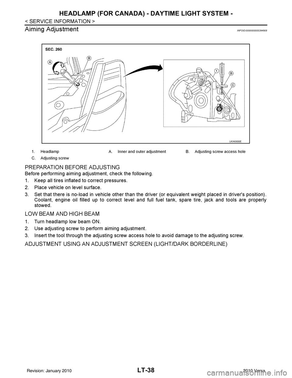
1. Turn headlamp low beam ON.
2. Use adjusting screw to perform aiming adjustment.
3. Insert the tool through the adjusting screw access hole to avoid damage to the adjusting screw.
ADJUSTMENT USING AN ADJUSTMENT SCREEN (LIGHT/DARK BORDERLINE)
1. Headlamp A. Inner and outer adjustment B. Adjusting screw access hole
C. Adjusting screw
LKIA0930E
Revision: January 20102010 Versa