Radiator NISSAN TIIDA 2010 Service Owner's Guide
[x] Cancel search | Manufacturer: NISSAN, Model Year: 2010, Model line: TIIDA, Model: NISSAN TIIDA 2010Pages: 3745, PDF Size: 73.67 MB
Page 997 of 3745
RADIATORCO-15
< ON-VEHICLE MAINTENANCE > [HR16DE]
C
D
E
F
G H
I
J
K L
M A
CO
NP
O
RADIATOR
Checking Radiator CapINFOID:0000000005398185
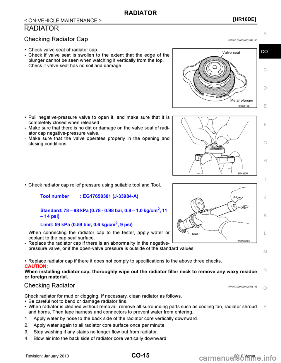
• Check valve seat of radiator cap.
- Check if valve seat is swollen to the extent that the edge of the
plunger cannot be seen when watching it vertically from the top.
- Check if valve seat has no soil and damage.
• Pull negative-pressure valve to open it, and make sure that it is completely closed when released.
- Make sure that there is no dirt or damage on the valve seat of radi-
ator cap negative-pressure valve.
- Make sure that the valve operates properly in the opening and closing conditions.
• Check radiator cap relief pressure using suitable tool and Tool.
- When connecting the radiator cap to the tester, apply water or coolant to the cap seal surface.
- Replace the radiator cap if there is an abnormality in the negative- pressure valve, or if the open-valve pressure is outside of the standard values.
• Replace radiator cap if there it does not comply to specifications to the above three checks.
CAUTION:
When installing radiator cap, thor oughly wipe out the radiator filler neck to remove any waxy residue
or foreign material.
Checking RadiatorINFOID:0000000005398186
Check radiator for mud or clogging. If necessary, clean radiator as follows.
• Be careful not to bend or damage radiator fins.
• When radiator is cleaned without removal, remove all surrounding parts such as cooling fan, radiator shroud and horns. Then tape harness and connectors to prevent water from entering.
1. Apply water by hose to the back side of the radiator core vertically downward.
2. Apply water again to all radiator core surface once per minute.
3. Stop washing if any stains no longer flow out from radiator.
4. Blow air into the back side of radiator core vertically downward.
PBIC2816E
SMA967B
Tool number : EG17650301 (J-33984-A)
Standard: 78 – 98 kPa (0.78 - 0.98 bar, 0.8 – 1.0 kg/cm
2, 11
– 14 psi)
Limit: 59 kPa (0.59 bar, 0.6 kg/cm
2, 9 psi)
WBIA0570E
Revision: January 20102010 Versa
Page 998 of 3745
CO-16
< ON-VEHICLE MAINTENANCE >[HR16DE]
RADIATOR
• Use compressed air lower than 490 kPa (4.9 bar, 5 kg/cm2, 71 psi) and keep distance more than 30 cm
(11.8 in).
5. Blow air again into all the radiator core surfaces once per minute until no water sprays out.
Revision: January 20102010 Versa
Page 999 of 3745
RADIATORCO-17
< ON-VEHICLE REPAIR > [HR16DE]
C
D
E
F
G H
I
J
K L
M A
CO
NP
O
ON-VEHICLE REPAIR
RADIATOR
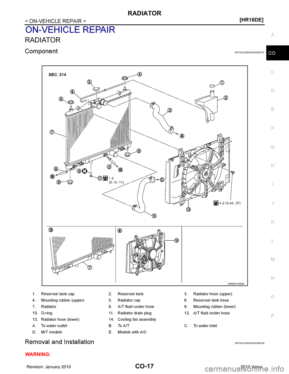
ComponentINFOID:0000000005398187
Removal and InstallationINFOID:0000000005398188
WARNING:
1. Reservoir tank cap
2. Reservoir tank 3. Radiator hose (upper)
4. Mounting rubber (upper) 5. Radiator cap6. Reservoir tank hose
7. Radiator 8. A/T fluid cooler hose9. Mounting rubber (lower)
10. O-ring 11. Radiator drain plug12. A/T fluid cooler hose
13. Radiator hose (lower) 14. Cooling fan assembly
A. To water outlet B. To A/TC. To water inlet
D. M/T models E. Models with A/C
AWBIA0128GB
Revision: January 20102010 Versa
Page 1000 of 3745
CO-18
< ON-VEHICLE REPAIR >[HR16DE]
RADIATOR
Do not remove radiator cap when
the engine is hot. Serious burns could occur from high-pressure
engine coolant escaping from radiator. Wrap a thick cloth around the cap. Slowly turn it a quarter of a
turn to release built-up pressure. Ca refully remove radiator cap by turning it all the way.
REMOVAL
1. Remove engine under cover. Refer to EI-15, "Removal and Installation".
2. Drain engine coolant from radiator. Refer to CO-12, "
Changing Engine Coolant".
CAUTION:
• Perform this step when engine is cold.
• Do not spill engine coolant on drive belt.
3. Remove air duct (inlet). Refer to EM-26, "
Exploded View".
4. Remove reservoir tank as follows:
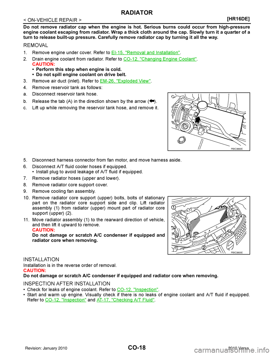
a. Disconnect reservoir tank hose.
b. Release the tab (A) in the direction shown by the arrow ( ).
c. Lift up while removing the reservoir tank hose, and remove it.
5. Disconnect harness connector from fan motor, and move harness aside.
6. Disconnect A/T fluid cooler hoses if equipped. • Install plug to avoid leakage of A/T fluid if equipped.
7. Remove radiator hoses (upper and lower).
8. Remove radiator core support cover.
9. Remove cooling fan assembly.
10. Remove radiator core support (upper) bolts, bolts of stationary part on the radiator core support side and clip. Lift radiator
assembly (1) from radiator (upper) mount part of radiator core
support (upper) (2).
11. Move radiator assembly (1) to the rearward direction of vehicle, and then lift it upward to remove.
CAUTION:
Do not damage or scratch A/ C condenser if equipped and
radiator core when removing.
INSTALLATION
Installation is in the reverse order of removal.
CAUTION:
Do not damage or scratch A/C condenser if equipped and radiator core when removing.
INSPECTION AFTER INSTALLATION
• Check for leaks of engine coolant. Refer to CO-12, "Inspection".
• Start and warm up engine. Visually check if there is no leaks of engine coolant and A/T fluid if equipped. Refer to CO-12, "
Inspection" and AT-17, "Checking A/T Fluid".
PBIC3800E
PBIC3805E
Revision: January 20102010 Versa
Page 1002 of 3745
CO-20
< ON-VEHICLE REPAIR >[HR16DE]
COOLING FAN
Removal and Installation
INFOID:0000000005398191
REMOVAL
1. Partially drain engine coolant from radiator. Refer to CO-12, "Changing Engine Coolant".
CAUTION:
• Perform this step when engine is cold.
• Do not spill engine coolant on drive belt.
2. Remove air duct (inlet). Refer to EM-26, "
Exploded View".
3. Remove reservoir tank.
4. Disconnect radiator hose (upper) at radiator side. Refer to CO-17, "
Component".
5. Disconnect harness connectors from fan motor, and move harness to aside.
6. Remove cooling fan assembly. CAUTION:
Be careful not to damage or scratch the radiator core.
INSTALLATION
Installation is in the reverse order of removal.
• Cooling fans are controlled by ECM. For details, refer to EC-415, "
Description".
CAUTION:
Be careful not to damage or scratch the radiator core.
Disassembly and AssemblyINFOID:0000000005714051
DISASSEMBLY
1. Remove cooling fan from fan motor.
2. Remove fan motor from fan shroud.
INSPECTION AFTER DISASSEMBLY
Inspect cooling fan for crack or unusual bend.
• If anything is found, replace cooling fan.
ASSEMBLY
Assembly is in the reverse order of disassembly.
Revision: January 20102010 Versa
Page 1003 of 3745
WATER PUMPCO-21
< ON-VEHICLE REPAIR > [HR16DE]
C
D
E
F
G H
I
J
K L
M A
CO
NP
O
WATER PUMP
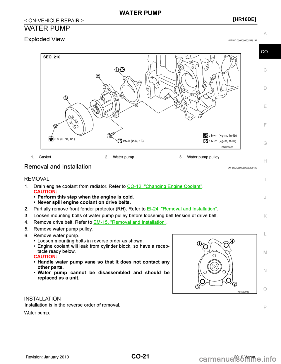
Exploded ViewINFOID:0000000005398192
Removal and InstallationINFOID:0000000005398193
REMOVAL
1. Drain engine coolant from radiator. Refer to
CO-12, "Changing Engine Coolant".
CAUTION:
• Perform this step when the engine is cold.
• Never spill engine coolant on drive belts.
2. Partially remove front fender protector (RH). Refer to EI-24, "
Removal and Installation".
3. Loosen mounting bolts of water pump pulley before loosening belt tension of drive belt.
4. Remove drive belt. Refer to EM-15, "
Removal and Installation".
5. Remove water pump pulley.
6. Remove water pump. • Loosen mounting bolts in reverse order as shown.
• Engine coolant will leak from cylinder block, so have a recep-tacle ready below.
CAUTION:
• Handle water pump vane so that it does not contact any other parts.
• Water pump cannot be disassembled and should be replaced as a unit.
INSTALLATION
Installation is in the reverse order of removal.
Water pump.
1. Gasket 2. Water pump3. Water pump pulley
PBIC3807E
KBIA3393J
Revision: January 20102010 Versa
Page 1005 of 3745
THERMOSTATCO-23
< ON-VEHICLE REPAIR > [HR16DE]
C
D
E
F
G H
I
J
K L
M A
CO
NP
O
THERMOSTAT
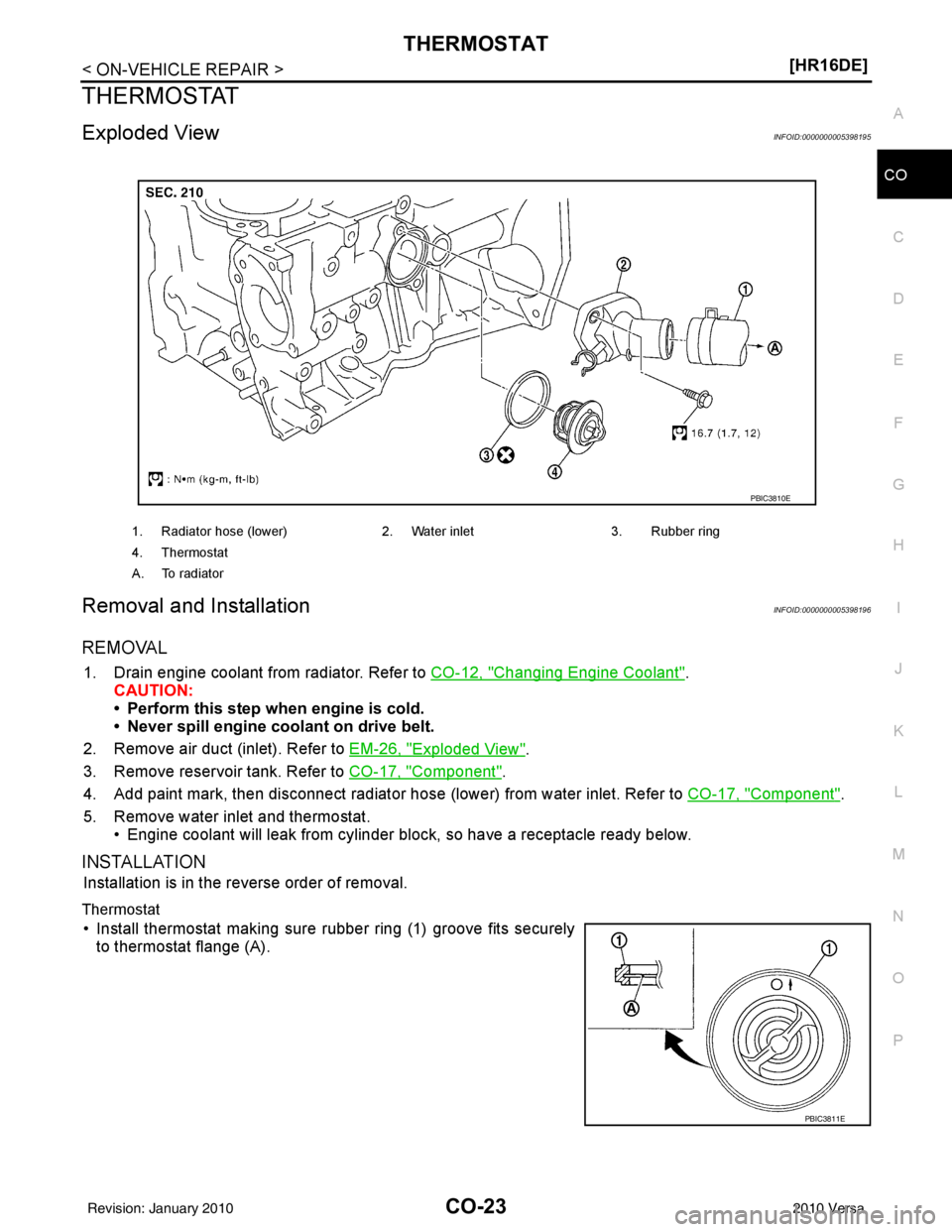
Exploded ViewINFOID:0000000005398195
Removal and InstallationINFOID:0000000005398196
REMOVAL
1. Drain engine coolant from radiator. Refer to
CO-12, "Changing Engine Coolant".
CAUTION:
• Perform this step when engine is cold.
• Never spill engine coolant on drive belt.
2. Remove air duct (inlet). Refer to EM-26, "
Exploded View".
3. Remove reservoir tank. Refer to CO-17, "
Component".
4. Add paint mark, then disconnect radiator hos e (lower) from water inlet. Refer to CO-17, "
Component".
5. Remove water inlet and thermostat. • Engine coolant will leak from cylinder block, so have a receptacle ready below.
INSTALLATION
Installation is in the reverse order of removal.
Thermostat
• Install thermostat making sure rubber ring (1) groove fits securelyto thermostat flange (A).
1. Radiator hose (lower) 2. Water inlet3. Rubber ring
4. Thermostat
A. To radiator
PBIC3810E
PBIC3811E
Revision: January 20102010 Versa
Page 1007 of 3745
WATER OUTLETCO-25
< ON-VEHICLE REPAIR > [HR16DE]
C
D
E
F
G H
I
J
K L
M A
CO
NP
O
WATER OUTLET
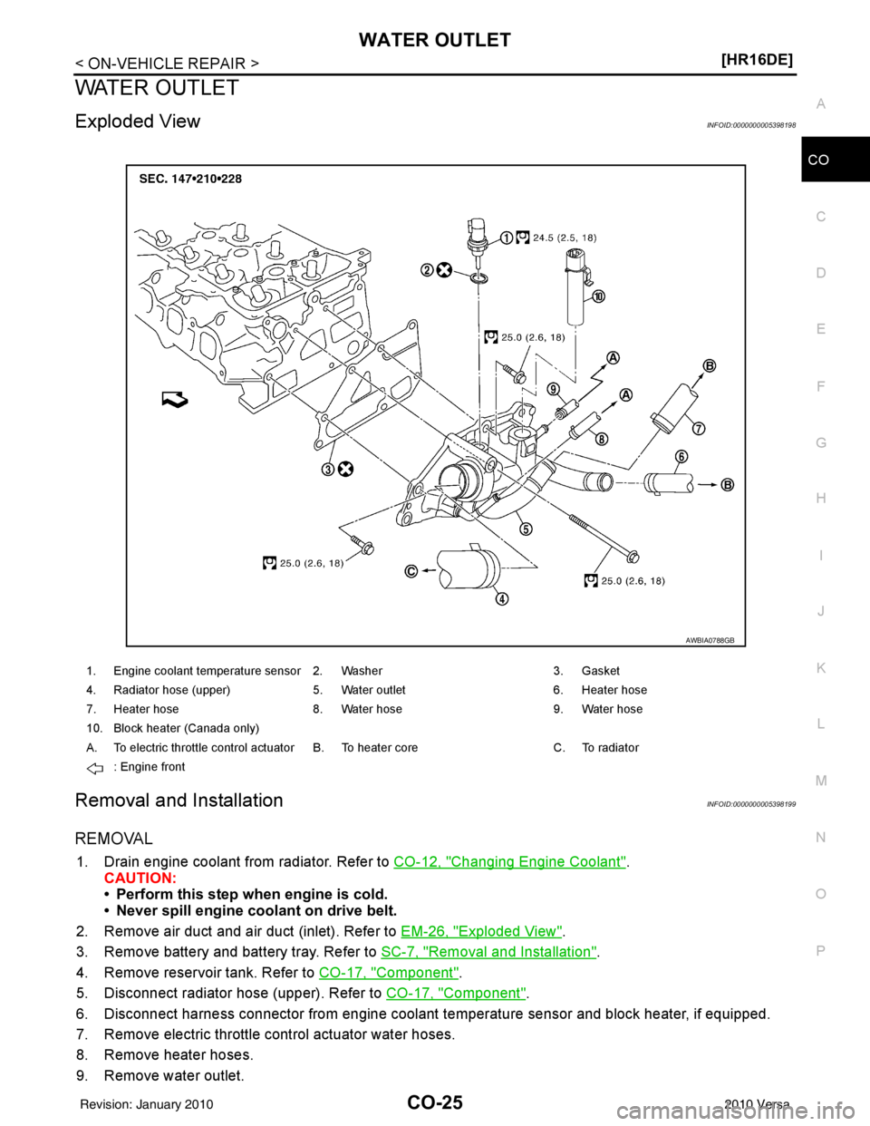
Exploded ViewINFOID:0000000005398198
Removal and InstallationINFOID:0000000005398199
REMOVAL
1. Drain engine coolant from radiator. Refer to
CO-12, "Changing Engine Coolant".
CAUTION:
• Perform this step when engine is cold.
• Never spill engine coolant on drive belt.
2. Remove air duct and air duct (inlet). Refer to EM-26, "
Exploded View".
3. Remove battery and battery tray. Refer to SC-7, "
Removal and Installation".
4. Remove reservoir tank. Refer to CO-17, "
Component".
5. Disconnect radiator hose (upper). Refer to CO-17, "
Component".
6. Disconnect harness connector from engine coolant temperature sensor and block heater, if equipped.
7. Remove electric throttle control actuator water hoses.
8. Remove heater hoses.
9. Remove water outlet.
1. Engine coolant temperature sensor 2. Washer 3. Gasket
4. Radiator hose (upper) 5. Water outlet 6. Heater hose
7. Heater hose 8. Water hose 9. Water hose
10. Block heater (Canada only)
A. To electric throttle control actuator B. To heater core C. To radiator
: Engine front
AWBIA0788GB
Revision: January 20102010 Versa
Page 1009 of 3745
SERVICE DATA AND SPECIFICATIONS (SDS)CO-27
< SERVICE DATA AND SPECIFICATIONS (SDS) [HR16DE]
C
D
E
F
G H
I
J
K L
M A
CO
NP
O
SERVICE DATA AND SPECIFICATIONS (SDS)
SERVICE DATA AND SPECIFICATIONS (SDS)
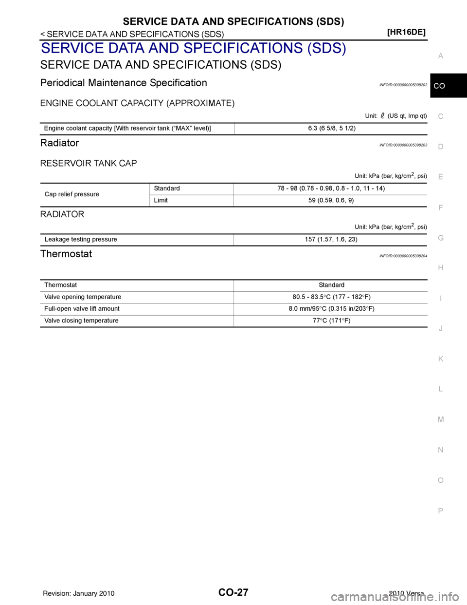
Periodical Maintenance SpecificationINFOID:0000000005398202
ENGINE COOLANT CAPACITY (APPROXIMATE)
Unit: (US qt, Imp qt)
RadiatorINFOID:0000000005398203
RESERVOIR TANK CAP
Unit: kPa (bar, kg/cm2, psi)
RADIATOR
Unit: kPa (bar, kg/cm2, psi)
ThermostatINFOID:0000000005398204
Engine coolant capacity [With reservoir tank (“MAX” level)]
6.3 (6 5/8, 5 1/2)
Cap relief pressureStandard
78 - 98 (0.78 - 0.98, 0.8 - 1.0, 11 - 14)
Limit 59 (0.59, 0.6, 9)
Leakage testing pressure 157 (1.57, 1.6, 23)
Thermostat Standard
Valve opening temperature 80.5 - 83.5°C (177 - 182 °F)
Full-open valve lift amount 8.0 mm/95°C (0.315 in/203 °F)
Valve closing temperature 77°C (171 °F)
Revision: January 20102010 Versa
Page 1013 of 3745
PREPARATIONCO-31
< SERVICE INFORMATION > [MR18DE]
C
D
E
F
G H
I
J
K L
M A
CO
NP
O
PREPARATION
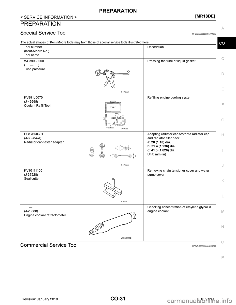
Special Service ToolINFOID:0000000005398208
The actual shapes of Kent-Moore tools may from
those of special service tools illustrated here.
Commercial Service ToolINFOID:0000000005398209
Tool number
(Kent-Moore No.)
Tool name Description
WS39930000
(—)
Tube pressure Pressing the tube of liquid gasket
KV991J0070
(J-45695)
Coolant Refill Tool Refilling engine cooling system
EG17650301
(J-33984-A)
Radiator cap tester adapter Adapting radiator cap tester to radiator cap
and radiator filler neck
a: 28 (1.10) dia.
b: 31.4 (1.236) dia.
c: 41.3 (1.626) dia.
Unit: mm (in)
K V 1 0 1111 0 0
(J-37228)
Seal cutter Removing chain tensioner cover and water
pump cover
—
(J-23688)
Engine coolant refractometer Checking concentration of ethylene glycol in
engine coolant
S-NT052
LMA053
S-NT564
NT046
WBIA0539E
Revision: January 20102010 Versa