glove box NISSAN TIIDA 2010 Service Owner's Guide
[x] Cancel search | Manufacturer: NISSAN, Model Year: 2010, Model line: TIIDA, Model: NISSAN TIIDA 2010Pages: 3745, PDF Size: 73.67 MB
Page 3424 of 3745

HARNESSPG-41
< SERVICE INFORMATION >
C
DE
F
G H
I
J
L
M A
B
PG
N
O P
C2 M6 W/4 : Steering lock solenoid D2 M43 W/20 : Audio unit
B3 M7 W/16 : Door mirror re mote control switch D2 M44 W/16 : Audio unit
A3 M8 W/16 : To D2 D2 M45 W/12 : Audio unit
A3 M9 W/16 : To D1 A1 M46 BR/2 : Front tweeter LH
E2 M10 GR/2 : Instrument panel antenna G1 M47 BR/2 : Front tweeter RH
G3 M11 W/4 : To B106 B2 M48 L/4 : Heated mirror relay
G4 M12 W/16 : To B101 E1 M49 W/24 : iPod ® adapter
G3 M13 W/24 : To B102 E1 M50 GR/16 : iPod ® side
G3 M14 W/24 : To B120 E2 M52 W/40 : Intelligent key unit
B4 M15 W/16 : To B23 B2 M53 W/16 : EPS control unit
B4 M16 W/24 : To B24 B3 M54 B/2 : EPS control unit
D5 M17 B/1 : Parking brake switch D2 M55 W/4 : Hazard switch
F2 M18 W/40 : BCM (body control module) B2 M57 — : Body ground
F2 M19 W/15 : BCM (body control module) F2 M59 W/2 : Glove box lamp
F3 M20 B/15 : BCM (body control module)C1 M60 L/2 : EPS control unit
C2 M21 W/4 : NATS antenna amp. F1 M61 — : Body ground
B3 M22 W/16 : Data link connector E2 M62 W/2 : Front blower motor
E3 M23 W/4 : Remote keyless entry receiver C1 M63 W/4 : Torque sensor
C1 M24 W/40 : Combination meter C3 M64 W/8 : Steering angle sensor
C3 M25 /2 : Diode-1 A2 M69 SMJ : To E7
B2 M26 W/6 : Ignition switch D2 M70 W/24 : AV control unit
C2 M27 GR/6 : Key switch and key lock solenoid D2 M71 W/9 : AV control unit
C2 M28 W/16 : Combination switch D1 M72 B/5 : USB interface and aux jack
C3 M29 Y/6 : Combination switch B2 M73 GR/6 : Key switch and ignition knob switch
C3 M30 GR/8 : Combination switch G3 M74 W/12 : To D102
A4 M31 W/24 : To B1 G3 M75 W/12 : To D101
E3 M32 W/4 : To M150 E1 M76 B/4 : USB interface and aux jack
D2 M33 B/15 : Front air control F2 M77 Y/4 : Front passenger air bag module
B3 M34 GR/6 : VDC OFF switch A2 M78 B/2 : To E11
D4 M35 Y/28 : Air bag diagnosis sensor unit B1 M79 — : Body ground
C3 M36 W/3 : Front passenger air bag OFF indicator D3 M150 W/4 : To M32
D4 M38 W/6 : A/T shift selector (with A/T) C3 M151 W/4 : Front blower motor resistor
D4 M38 W/6 : CVT shift selector (without intelligent
key)
Revision: January 20102010 Versa
Page 3495 of 3745
TROUBLE DIAGNOSISRF-11
< FUNCTION DIAGNOSIS >
C
DE
F
G H
J
K L
M A
B
RF
N
O P
FUNCTION DIAGNOSIS
TROUBLE DIAGNOSIS
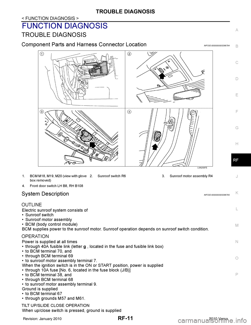
Component Parts and Har ness Connector LocationINFOID:0000000005396794
System DescriptionINFOID:0000000005396795
OUTLINE
Electric sunroof system consists of
• Sunroof switch
• Sunroof motor assembly
• BCM (body control module)
BCM supplies power to the sunroof motor. S unroof operation depends on sunroof switch condition.
OPERATION
Power is supplied at all times
• through 40A fusible link (letter g , located in the fuse and fusible link box)
• to BCM terminal 70, and
• through BCM terminal 69
• to sunroof motor assembly terminal 7.
When the ignition switch is in the ON or START position, power is supplied
• through 10A fuse [No. 6, located in the fuse block (J/B)]
• to BCM terminal 38, and
• through BCM terminal 68
• to sunroof motor assembly terminal 9.
Ground is supplied
• to BCM terminal 67
• through grounds M57 and M61.
TILT UP/SLIDE CLOSE OPERATION
When up/close switch is pressed, ground is supplied
LIIA2597E
1. BCM M18, M19, M20 (view with glove
box removed) 2. Sunroof switch R6 3. Sunroof motor assembly R4
4. Front door switch LH B8, RH B108
Revision: January 20102010 Versa
Page 3686 of 3745

TIRE PRESSURE MONITORING SYSTEMWT-9
< SERVICE INFORMATION >
C
DF
G H
I
J
K L
M A
B
WT
N
O P
TIRE PRESSURE MO NITORING SYSTEM
System ComponentINFOID:0000000005397093
System DescriptionINFOID:0000000005397094
BODY CONTROL MODULE (BCM)
The BCM is shown with the glove box removed. The BCM reads the
air pressure signal received by the remote keyless entry receiver,
and controls the low tire pressure warning lamp as shown below. It
also has a self-diagnosis function to detect a system malfunction.
TRANSMITTER
WEIA0185E
1. BCM
M18, M20 2. Transmitters 3. Tire pressure warning check connector
M39
4. Combination meter M24 5. Remote keyless entry receiver
M23
Condition Low tire pressure warning lamp
System normal On for 1 second after ignition ON
Tire less than 193 kPa (2.0 kg/cm
2 , 28 psi)
[Flat tire] ON
Tire pressure monitoring system malfunc-
tion After key ON, flashes once per sec-
ond for 1 minute, then stays ON
WEIA0187E
Revision: January 20102010 Versa
Page 3687 of 3745
WT-10
< SERVICE INFORMATION >
TIRE PRESSURE MONITORING SYSTEM
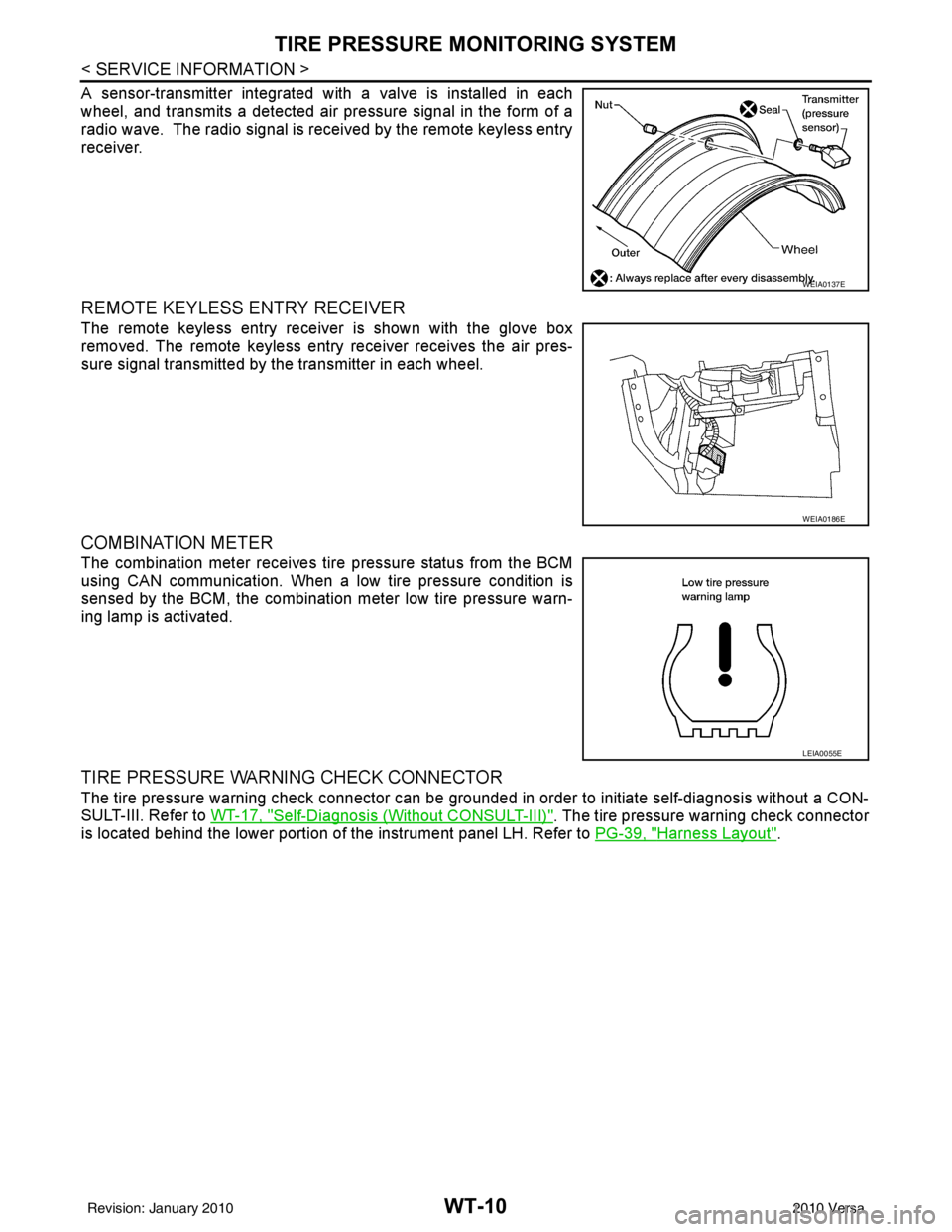
A sensor-transmitter integrated with a valve is installed in each
wheel, and transmits a detected air pressure signal in the form of a
radio wave. The radio signal is received by the remote keyless entry
receiver.
REMOTE KEYLESS ENTRY RECEIVER
The remote keyless entry receiver is shown with the glove box
removed. The remote keyless entry receiver receives the air pres-
sure signal transmitted by the transmitter in each wheel.
COMBINATION METER
The combination meter receives tire pressure status from the BCM
using CAN communication. When a low tire pressure condition is
sensed by the BCM, the combination meter low tire pressure warn-
ing lamp is activated.
TIRE PRESSURE WARNING CHECK CONNECTOR
The tire pressure warning check connector can be grounded in order to initiate self-diagnosis without a CON-
SULT-III. Refer to WT-17, "
Self-Diagnosis (Without CONSULT-III)". The tire pressure warning check connector
is located behind the lower portion of the instrument panel LH. Refer to PG-39, "
Harness Layout".
WEIA0137E
WEIA0186E
LEIA0055E
Revision: January 20102010 Versa
Page 3710 of 3745
FRONT WIPER AND WASHER SYSTEMWW-5
< SERVICE INFORMATION >
C
DE
F
G H
I
J
L
M A
B
WW
N
O P
FRONT WIPER AND WASHER SYSTEM
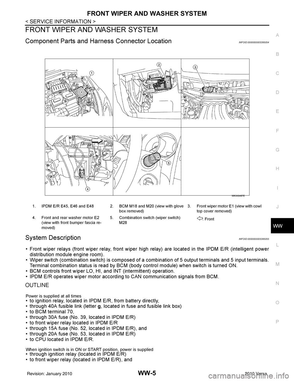
Component Parts and Har ness Connector LocationINFOID:0000000005395054
System DescriptionINFOID:0000000005395055
• Front wiper relays (front wiper relay, front wiper high relay) are located in the IPDM E/R (intelligent power
distribution module engine room).
• Wiper switch (combination switch) is composed of a combination of 5 output terminals and 5 input terminals.
Terminal combination status is read by BCM (body control module) when switch is turned ON.
• BCM controls front wiper LO, HI, and INT (intermittent) operation.
• IPDM E/R operates wiper motor accordi ng to CAN communication signals from BCM.
OUTLINE
Power is supplied at all times• to ignition relay, located in IPDM E/R, from battery directly,
• through 40A fusible link (letter g, located in fuse and fusible link box)
• to BCM terminal 70,
• through 30A fuse (No. 39, located in IPDM E/R)
• to front wiper relay located in IPDM E/R
• through 15A fuse (No. 52, located in IPDM E/R), and
• through 20A fuse (No. 53, located in IPDM E/R)
• to CPU located in IPDM E/R.
When ignition switch is in ON or START position, power is supplied • through ignition relay (located in IPDM E/R)
• to front wiper relay (located in IPDM E/R), and
1. IPDM E/R E45, E46 and E48 2. BCM M18 and M20 (view with glove
box removed)3. Front wiper motor E1
(view with cowl
top cover removed)
4. Front and rear washer motor E2 (view with front bumper fascia re-
moved) 5. Combination switch (wiper switch)
M28 : Front
WKIA5467E
Revision: January 20102010 Versa
Page 3731 of 3745
WW-26
< SERVICE INFORMATION >
REAR WIPER AND WASHER SYSTEM
REAR WIPER AND WASHER SYSTEM
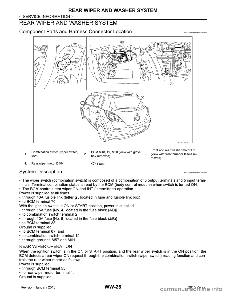
Component Parts and Harness Connector LocationINFOID:0000000005395084
System DescriptionINFOID:0000000005395085
• The wiper switch (combination switch) is composed of a combination of 5 output terminals and 5 input termi-
nals. Terminal combination status is read by the BC M (body control module) when switch is turned ON.
• The BCM controls rear wiper ON and INT (intermittent) operation.
Power is supplied at all times
• through 40A fusible link (letter g , located in fuse and fusible link box)
• to BCM terminal 70.
With the ignition switch in ON or START position, power is supplied
• through 15A fuse [No. 4, located in the fuse block (J/B)]
• to combination switch terminal 2
• through 10A fuse [No. 6, located in the fuse block (J/B)]
• to BCM terminal 38.
Ground is supplied
• to BCM terminal 67, and
• to combination switch terminal 12
• through grounds M57 and M61.
REAR WIPER OPERATION
When the ignition switch is in the ON or START position, and the rear wiper switch is in the ON position, the
BCM detects a rear wiper ON request through the combination switch (wiper switch) reading function and con-
trols the rear wiper motor as follows.
Power is supplied
• through BCM terminal 55
• to rear wiper motor terminal 1.
Ground is supplied
WKIA5507E
1. Combination switch (wiper switch)
M28 2.BCM M18, 19, M20 (view with glove
box removed) 3.Front and rear washer motor E2
(view with front bumper fascia re-
moved)
4. Rear wiper motor D404 : Front
Revision: January 20102010 Versa