glove box NISSAN TIIDA 2010 Service Owner's Manual
[x] Cancel search | Manufacturer: NISSAN, Model Year: 2010, Model line: TIIDA, Model: NISSAN TIIDA 2010Pages: 3745, PDF Size: 73.67 MB
Page 2808 of 3745
IP-24
< ON-VEHICLE REPAIR >
INSTRUMENT PANEL ASSEMBLY
Disassembly
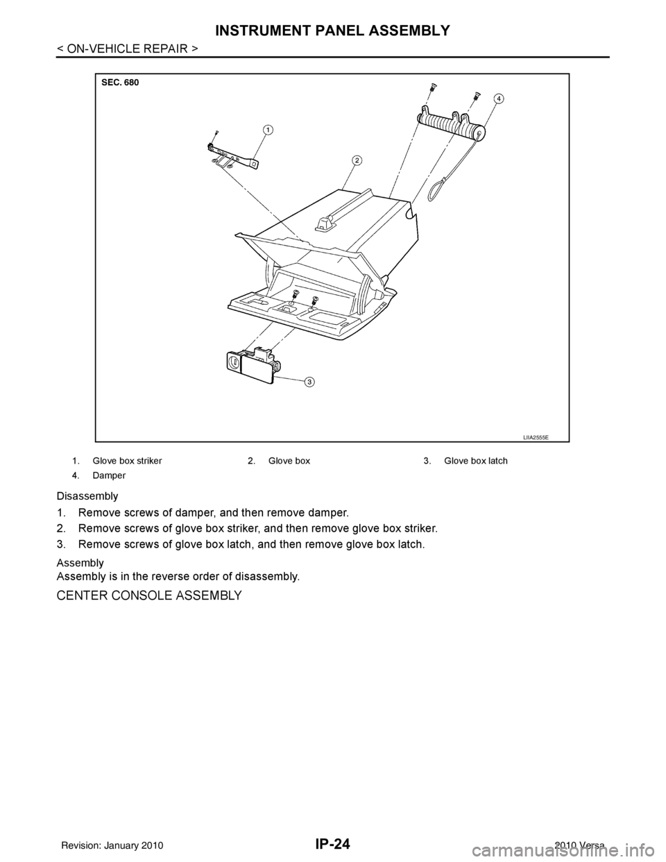
1. Remove screws of damper, and then remove damper.
2. Remove screws of glove box striker, and then remove glove box striker.
3. Remove screws of glove box latch, and then remove glove box latch.
Assembly
Assembly is in the reverse order of disassembly.
CENTER CONSOLE ASSEMBLY
1. Glove box striker2. Glove box 3. Glove box latch
4. Damper
LIIA2555E
Revision: January 20102010 Versa
Page 3001 of 3745
LT-6
< SERVICE INFORMATION >
HEADLAMP (FOR USA)
HEADLAMP (FOR USA)
Component Parts and Harness Connector LocationINFOID:0000000005394875
System DescriptionINFOID:0000000005394876
Headlamp operation is controlled by the BCM (body c ontrol module) based on inputs from the combination
switch (lighting switch). When the lighting switch is pl aced in the 2ND position, the BCM receives an input sig-
nal requesting the headlamps (and tail lamps) illuminate. The BCM sends a signal, via the CAN communica-
tion lines, to the IPDM E/R (intelligent power di stribution module engine room) requesting the headlamps be
turned ON. The CPU (central processing unit) located in the IPDM E/R controls ground for the headlamp high
and headlamp low relay coils. These relays direct power to the respective headlamps, which then illuminate.
OUTLINE
Power is supplied at all times
• to headlamp high relay RH and LH (located in IPDM E/R),
• to headlamp low relay (located in IPDM E/R),
• to ignition relay (located in IPDM E/R),
• through 15A fuse (No. 52, located in IPDM E/R) and
• through 20A fuse (No. 53, located in IPDM E/R)
• to CPU located in IPDM E/R,
• through 40A fusible link (letter g , located in fuse and fusible link block)
• to BCM terminal 70,
• through 10A fuse [No. 8, located in fuse block (J/B)]
• to BCM terminal 57, and
• through 10A fuse [No. 13, located in fuse block (J/B)]
• to combination meter terminal 27.
With the ignition switch in the ON or START position, power is supplied
• to the ignition relay (located in IPDM E/R),
• through 10A fuse [No. 6, located in fuse block (J/B)]
• to BCM terminal 38,
• through 10A fuse [No. 3, located in fuse block (J/B)]
• to combination meter terminal 28.
With the ignition switch in the ACC or ON position, power is supplied
• through 10A fuse [No. 20, located in fuse block (J/B)]
• to BCM terminal 11.
Ground is supplied
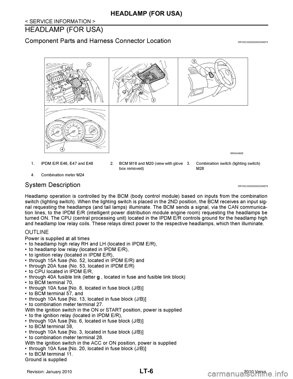
1. IPDM E/R E46, E47 and E48 2. BCM M18 and M20 (view with glove
box removed)3. Combination switch (lighting switch)
M28
4. Combination meter M24
WKIA5469E
Revision: January 20102010 Versa
Page 3023 of 3745
LT-28
< SERVICE INFORMATION >
HEADLAMP (FOR CANADA) - DAYTIME LIGHT SYSTEM -
HEADLAMP (FOR CANADA) - DAYTIME LIGHT SYSTEM -
Component Parts and Harness Connector LocationINFOID:0000000005394896
System DescriptionINFOID:0000000005394897
Headlamp operation is controlled by the BCM (body c ontrol module) based on inputs from the combination
switch (lighting switch). When the lighting switch is pl aced in the 2ND position, the BCM receives an input sig-
nal requesting the headlamps (and tail lamps) illuminate. The request is then communicated to the IPDM E/R
(intelligent power distribution module engine room) vi a the CAN communication lines. The CPU (central pro-
cessing unit) located in the IPDM E/R controls ground for the headlamp high and headlamp low relay coils.
These relays direct power to the respective headlamps , which then illuminate. When the headlamp switch is
OFF or in the 1ST position (parking lamps ON), the parking brake is released and the engine is running, the
IPDM E/R de-energizes the headlamp relays and supplies ground to the daytime light relay 1 to actuate the
daytime light function.
OUTLINE
Power is supplied at all times
• to headlamp high relay RH and LH (located in IPDM E/R)
• to headlamp low relay (located in IPDM E/R) and
• to ignition relay (located in IPDM E/R)
• through 15A fuse (No. 52, located in IPDM E/R) and
• through 20A fuse (No. 53, located in IPDM E/R)
• to CPU located in IPDM E/R,
• through 40A fusible link (letter g , located in fuse and fusible link box)
• to BCM terminal 70,
• through 10A fuse [No. 8, located in fuse block (J/B)]
• to BCM terminal 57,
• through 10A fuse [No. 13, located in fuse block (J/B)]
• to combination meter terminal 27,
• through 10A fuse (No. 26, located in fuse and fusible link box)
• to the daytime light relay 1.
With the ignition switch in the ON or START position, power is supplied
• to the ignition relay (located in IPDM E/R),
• through 10A fuse [No. 6, located in fuse block (J/B)]
• to BCM terminal 38,
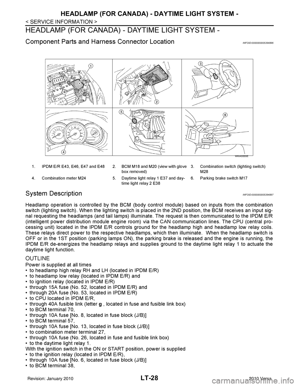
1. IPDM E/R E43, E46, E47 and E48 2. BCM M18 and M20 (view with glove
box removed)3. Combination switch (lighting switch)
M28
4. Combination meter M24 5. Daytime light relay 1 E37 and day-
time light relay 2 E38 6. Parking brake switch M17
WKIA5555E
Revision: January 20102010 Versa
Page 3037 of 3745
LT-42
< SERVICE INFORMATION >
FRONT FOG LAMP
FRONT FOG LAMP
Component Parts and Harness Connector LocationINFOID:0000000005394912
System DescriptionINFOID:0000000005394913
The front fog lamps are controlled by lighting switch inputs to the BCM (body control module). The lighting
switch must be in the 1ST or 2ND position with t he high beams OFF before the BCM will request the IPDM E/
R (intelligent power distribution module engine room) to turn the front fog lamps on. The BCM requests the
front fog lamps over the CAN communication lines to the IPDM E/R. The CPU (central processing unit) of the
IPDM E/R controls the front fog lamp relay coil ground. When energized, the relay directs power to the front
fog lamps.
OUTLINE
Power is supplied at all times:
• to front fog lamp relay (located in IPDM E/R),
• to ignition relay (located in IPDM E/R),
• through 15A fuse (No. 52, located in IPDM E/R) and
• through 20A fuse (No. 53, located in IPDM E/R)
• to CPU located in IPDM E/R,
• through 40A fusible link (letter g , located in the fuse and fusible link box)
• to BCM terminal 70,
• through 10A fuse [No. 8, located in fuse block (J/B)]
• to BCM terminal 57,
• through 10A fuse [No. 13, located in fuse block (J/B)]
• to combination meter terminal 27.
With the ignition switch in the ON or START position, power is supplied:
• to ignition relay (located in IPDM E/R),
• through 10A fuse [No. 6, located in fuse block (J/B)]
• to BCM terminal 38.
With the ignition switch in the ACC or ON position, power is supplied
• through 10A fuse [No. 20, located in fuse block (J/B)]
• to BCM terminal 11.
Ground is supplied
• to BCM terminal 67
• through grounds M57 and M61,
• to IPDM E/R terminals 39 and 59
• through grounds E15 and E24.
FOG LAMP OPERATION
The front fog lamp switch is built into the lighting s witch. The lighting switch must be in 1ST position or 2ND
position and front fog lamp switch must be ON position fo r front fog lamp operation. The fog lamp will not oper-
ate with the high beam headlamps ON.
When the front fog lamp switch is in the ON positi on, the BCM sends a request, via the CAN communication
lines, to the CPU of the IPDM E/R to ground the coil side of the front fog lamp relay. The front fog lamp relay
then directs power
• through 15A fuse (No. 56, located in IPDM E/R)
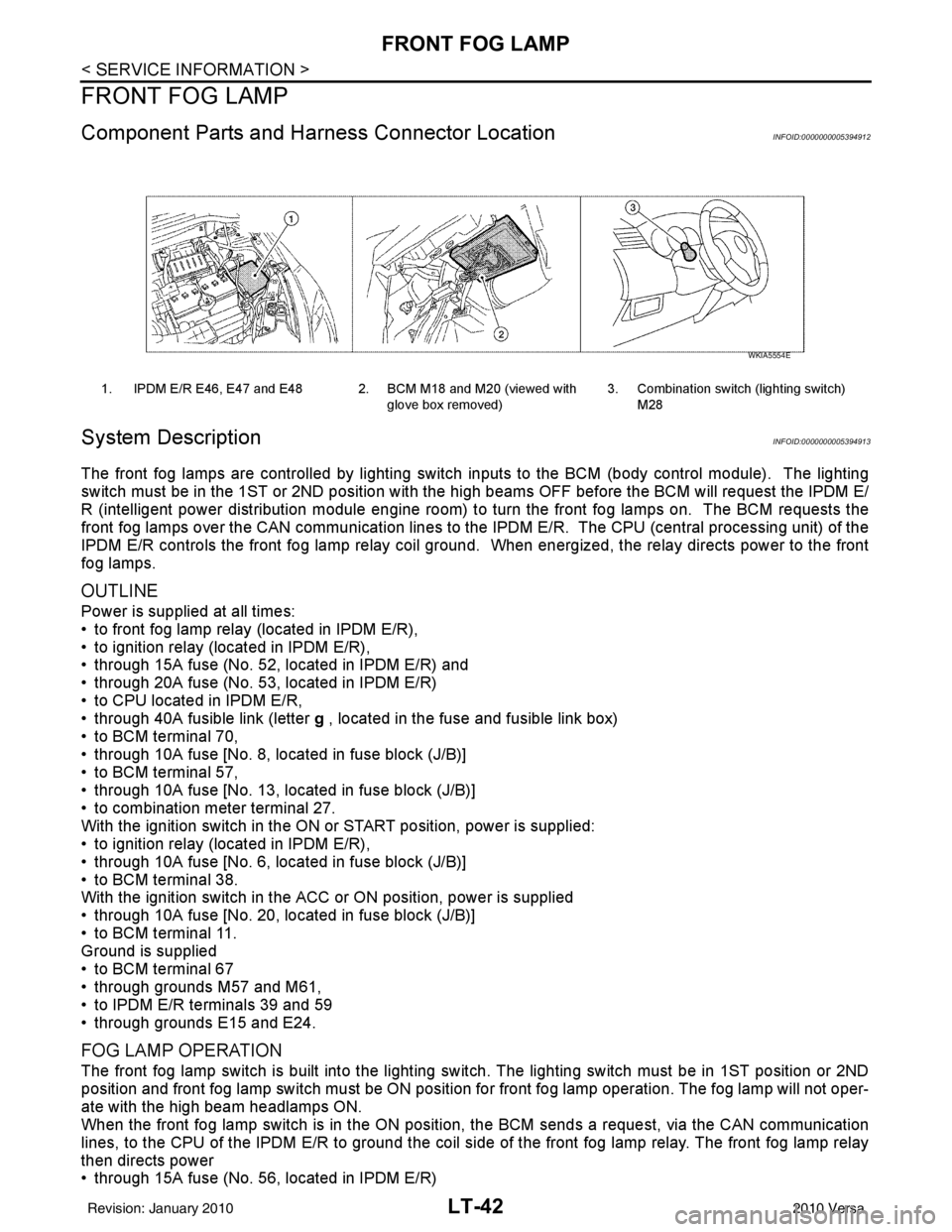
1. IPDM E/R E46, E47 and E48 2. BCM M18 and M20 (viewed with
glove box removed)3. Combination switch (lighting switch)
M28
WKIA5554E
Revision: January 20102010 Versa
Page 3046 of 3745
TURN SIGNAL AND HAZARD WARNING LAMPSLT-51
< SERVICE INFORMATION >
C
DE
F
G H
I
J
L
M A
B
LT
N
O P
TURN SIGNAL AND HA ZARD WARNING LAMPS
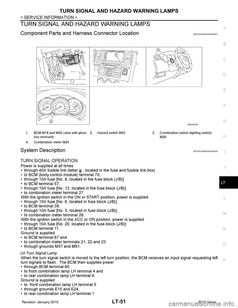
Component Parts and Har ness Connector LocationINFOID:0000000005394927
System DescriptionINFOID:0000000005394928
TURN SIGNAL OPERATION
Power is supplied at all times
• through 40A fusible link (letter g , located in the fuse and fusible link box)
• to BCM (body control module) terminal 70,
• through 10A fuse [No. 8, located in the fuse block (J/B)]
• to BCM terminal 57,
• through 10A fuse [No. 13, located in the fuse block (J/B)]
• to combination meter terminal 27.
With the ignition switch in the ON or START position, power is supplied
• through 10A fuse [No. 6, located in fuse block (J/B)]
• to BCM terminal 38,
• through 10A fuse [No. 3, located in fuse block (J/B)]
• to combination meter terminal 28.
With the ignition switch in the ACC or ON position, power is supplied
• through 10A fuse [No. 20, located in the fuse block (J/B)]
• to BCM terminal 11.
Ground is supplied
• to BCM terminal 67 and
• to combination meter terminals 21, 22 and 23
• through grounds M57 and M61.
LH Turn Signal Lamp
When the turn signal switch is moved to the left turn position, the BCM receives an input signal requesting left
turn signals to flash. The BCM then supplies power
• through BCM terminal 60
• to front combination lamp LH terminal 4 and
• to rear combination lamp LH terminal 6.
Ground is supplied
• to front combination lamp LH terminal 5
• through grounds E15 and E24,
• to rear combination lamp LH terminal 1
1. BCM M18 and M20 (view with glove
box removed) 2. Hazard switch M55
3. Combination switch (lighting switch)
M28
4. Combination meter M24
WKIA5679E
Revision: January 20102010 Versa
Page 3070 of 3745
PARKING, LICENSE PLATE AND TAIL LAMPS
LT-75
< SERVICE INFORMATION >
C
D E
F
G H
I
J
L
M A
B
LT
N
O P
PARKING, LICENSE PLATE AND TAIL LAMPS
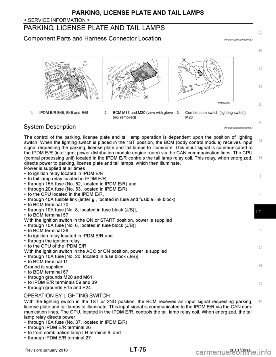
Component Parts and Har ness Connector LocationINFOID:0000000005394963
System DescriptionINFOID:0000000005394964
The control of the parking, license plate and tail lamp operation is dependent upon the position of lighting
switch. When the lighting switch is placed in the 1ST position, the BCM (body control module) receives input
signal requesting the parking, license plate and tail lamps to illuminate. This input signal is communicated to
the IPDM E/R (intelligent power distribution module engine room) via the CAN communication lines. The CPU
(central processing unit) located in the IPDM E/R contro ls the tail lamp relay coil. This relay, when energized,
directs power to parking, license plate and tail lamps, which then illuminate.
Power is supplied at all times
• to ignition relay located in IPDM E/R,
• to tail lamp relay located in IPDM E/R,
• through 15A fuse (No. 52, located in IPDM E/R) and
• through 20A fuse (No. 53, located in IPDM E/R)
• to the CPU located in the IPDM E/R,
• through 40A fusible link (letter g , located in fuse and fusible link block)
• to BCM terminal 70,
• through 10A fuse [No. 8, located in fuse block (J/B)],
• to BCM terminal 57.
With the ignition switch in the ON or START position, power is supplied
• through 10A fuse [No. 6, located in fuse block (J/B)]
• to BCM terminal 38,
• to ignition relay located in IPDM E/R and
• through the ignition relay
• to the CPU of the IPDM E/R.
With the ignition switch in the ACC or ON position, power is supplied
• through 10A fuse [No. 20, located in fuse block (J/B)]
• to BCM terminal 11.
Ground is supplied
• to BCM terminal 67
• through grounds M20 and M61,
• to IPDM E/R terminals 59 and 39
• through grounds E15 and E24.
OPERATION BY LIGHTING SWITCH
With the lighting switch in the 1ST or 2ND positi on, the BCM receives an input signal requesting parking,
license plate and tail lamps to illuminate. This input si gnal is communicated to the IPDM E/R via the CAN com-
munication lines. The CPU, located in the IPDM E/R, c ontrols the tail lamp relay coil. When energized, the tail
lamp relay directs power
• through 10A fuse (No. 37, located in IPDM E/R),
• through IPDM E/R terminal 26
• to front combination lamp LH terminal 6, and
• through IPDM E/R terminal 27
1. IPDM E/R E45, E46 and E48 2. BCM M18 and M20 (view with glove
box removed)3. Combination switch (lighting switch)
M28
WKIA5554E
Revision: January 20102010 Versa
Page 3089 of 3745
LT-94
< SERVICE INFORMATION >
INTERIOR ROOM LAMP
INTERIOR ROOM LAMP
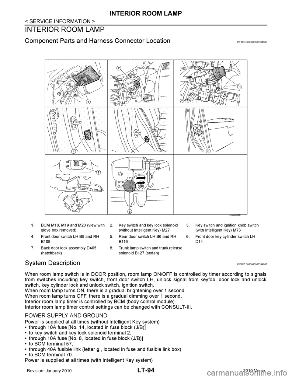
Component Parts and Harness Connector LocationINFOID:0000000005394986
System DescriptionINFOID:0000000005394987
When room lamp switch is in DOOR position, room lamp ON/OFF is controlled by timer according to signals
from switches including key switch, front door switch LH, unlock signal from keyfob, door lock and unlock
switch, key cylinder lock and unlock switch, ignition switch.
When room lamp turns ON, there is a gradual brightening over 1 second.
When room lamp turns OFF, there is a gradual dimming over 1 second.
Interior room lamp timer is controlled by BCM (body control module).
Interior room lamp timer control settings can be changed with CONSULT-III.
POWER SUPPLY AND GROUND
Power is supplied at all times (without Intelligent Key system)
• through 10A fuse [No. 14, located in fuse block (J/B)]
• to key switch and key lock solenoid terminal 2,
• through 10A fuse [No. 8, located in fuse block (J/B)]
• to BCM terminal 57,
• through 40A fusible link (letter g , located in fuse and fusible link box)
• to BCM terminal 70.
Power is supplied at all times (with Intelligent Key system)
1. BCM M18, M19 and M20 (view with
glove box removed) 2. Key switch and key lock solenoid
(without Intelligent Key) M27 3. Key switch and ignition knob switch
(with Intelligent Key) M73
4. Front door switch LH B8 and RH B108 5. Rear door switch LH B6 and RH
B116 6. Front door key cylinder switch LH
D14
7. Back door lock assembly D405 (hatchback) 8. Trunk lamp switch and trunk release
solenoid B127 (sedan)
LIIA2936E
Revision: January 20102010 Versa
Page 3172 of 3745
CHASSIS AND BODY MAINTENANCEMA-37
< SERVICE INFORMATION >
C
DE
F
G H
I
J
K
M A
B
MA
N
O P
CHASSIS AND BODY MAINTENANCE
IN-CABIN MICROFILTER
IN-CABIN MICROFILTER : Removal and InstallationINFOID:0000000005714334
FUNCTION
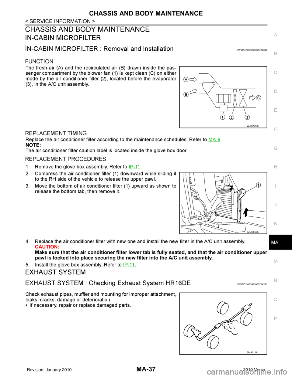
The fresh air (A) and the recirculated air (B) drawn inside the pas-
senger compartment by the blower fan (1) is kept clean (C) on either
mode by the air conditioner filter (2), located before the evaporator
(3), in the A/C unit assembly.
REPLACEMENT TIMING
Replace the air conditioner filter according to the maintenance schedules. Refer to MA-9.
NOTE:
The air conditioner filter caution label is located inside the glove box door.
REPLACEMENT PROCEDURES
1. Remove the glove box assembly. Refer to IP-11.
2. Compress the air conditioner filter (1) downward while sliding it to the RH side of the vehicle to release the upper pawl.
3. Move the bottom of air conditioner filter (1) upward as shown to
release the bottom tab, then remove it.
4. Replace the air conditioner filter with new one and in stall the new filter in the A/C unit assembly.
CAUTION:
Make sure that the air cond itioner filter lower tab is fully seated, and that the air conditioner upper
pawl is locked into place securing the new filter into the A/C unit assembly.
5. Install the glove box assembly. Refer to IP-11
.
EXHAUST SYSTEM
EXHAUST SYSTEM : Checking Exhaust System HR16DEINFOID:0000000005714335
Check exhaust pipes, muffler and mounting for improper attachment,
leaks, cracks, damage or deterioration.
• If necessary, repair or replace damaged parts.
WJIA2253E
SJIA0652E
SMA211A
Revision: January 20102010 Versa
Page 3345 of 3745
MTC-66
< SERVICE INFORMATION >
MODE DOOR
MODE DOOR
Mode Door Cable AdjustmentINFOID:0000000005396514
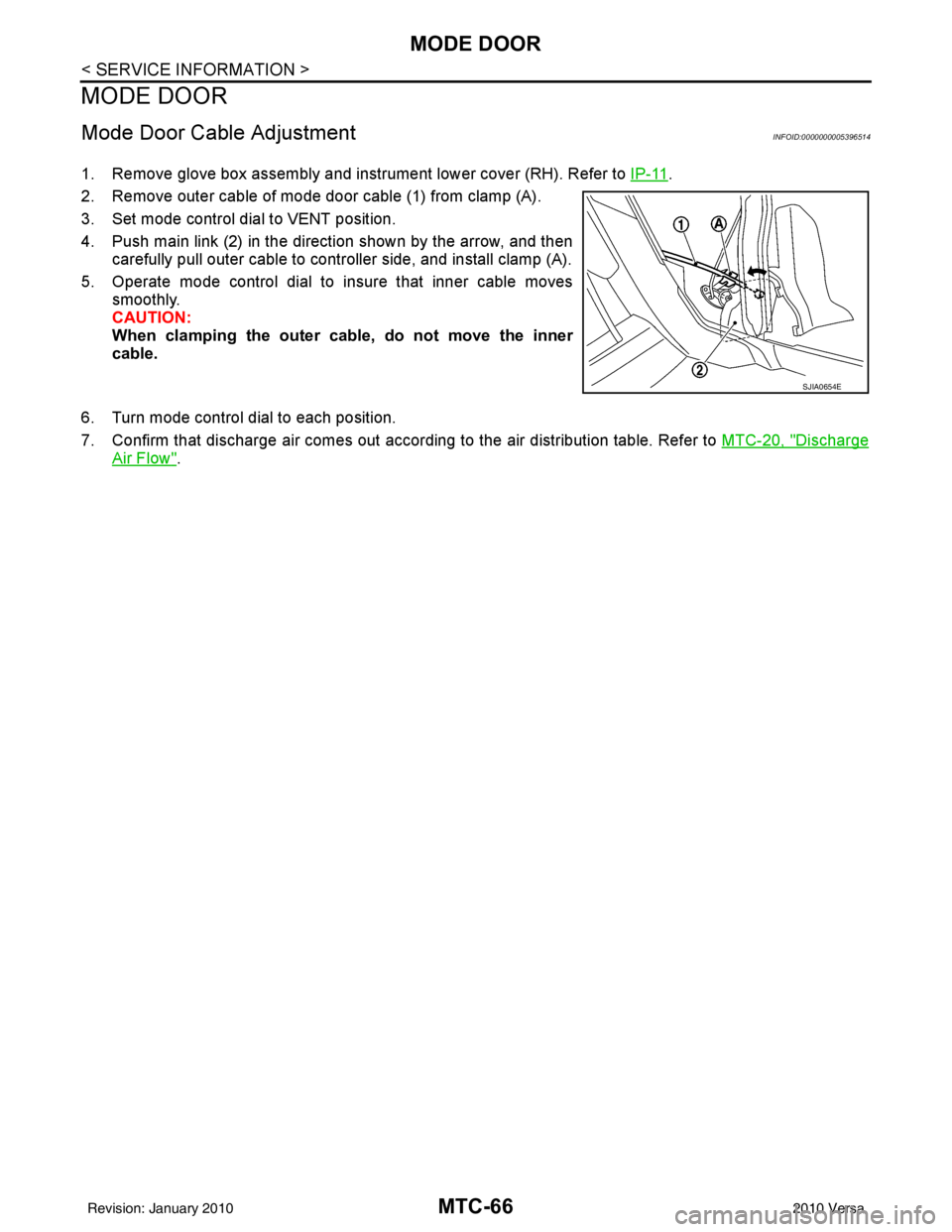
1. Remove glove box assembly and instrument lower cover (RH). Refer to IP-11.
2. Remove outer cable of mode door cable (1) from clamp (A).
3. Set mode control dial to VENT position.
4. Push main link (2) in the direction shown by the arrow, and then carefully pull outer cable to controller side, and install clamp (A).
5. Operate mode control dial to insure that inner cable moves smoothly.
CAUTION:
When clamping the outer cable, do not move the inner
cable.
6. Turn mode control dial to each position.
7. Confirm that discharge air comes out according to the air distribution table. Refer to MTC-20, "
Discharge
Air Flow".
SJIA0654E
Revision: January 20102010 Versa
Page 3348 of 3745
AIR CONDITIONER FILTERMTC-69
< SERVICE INFORMATION >
C
DE
F
G H
I
K L
M A
B
MTC
N
O P
AIR CONDITIONER FILTER
Removal and InstallationINFOID:0000000005396517
FUNCTION
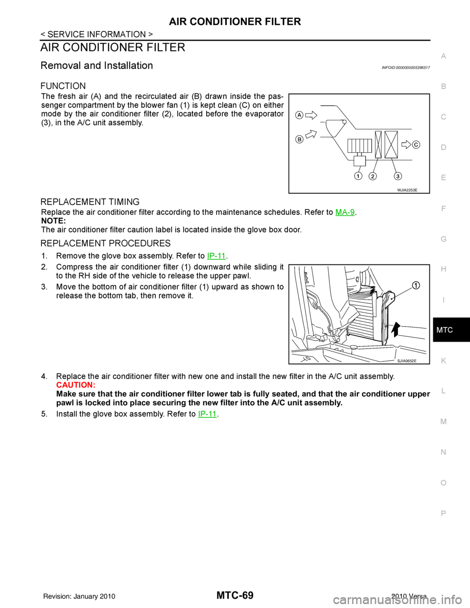
The fresh air (A) and the recirculated air (B) drawn inside the pas-
senger compartment by the blower fan (1) is kept clean (C) on either
mode by the air conditioner filter (2), located before the evaporator
(3), in the A/C unit assembly.
REPLACEMENT TIMING
Replace the air conditioner filter according to the maintenance schedules. Refer to MA-9.
NOTE:
The air conditioner filter caution label is located inside the glove box door.
REPLACEMENT PROCEDURES
1. Remove the glove box assembly. Refer to IP-11.
2. Compress the air conditioner filter (1) downward while sliding it to the RH side of the vehicle to release the upper pawl.
3. Move the bottom of air conditioner filter (1) upward as shown to
release the bottom tab, then remove it.
4. Replace the air conditioner filter with new one and in stall the new filter in the A/C unit assembly.
CAUTION:
Make sure that the air cond itioner filter lower tab is fully seated, and that the air conditioner upper
pawl is locked into place securing the new filter into the A/C unit assembly.
5. Install the glove box assembly. Refer to IP-11
.
WJIA2253E
SJIA0652E
Revision: January 20102010 Versa