throttle control NISSAN TIIDA 2010 Service Service Manual
[x] Cancel search | Manufacturer: NISSAN, Model Year: 2010, Model line: TIIDA, Model: NISSAN TIIDA 2010Pages: 3745, PDF Size: 73.67 MB
Page 1032 of 3745
CO-50
< SERVICE INFORMATION >[MR18DE]
WATER OUTLET AND WATER CONTROL VALVE
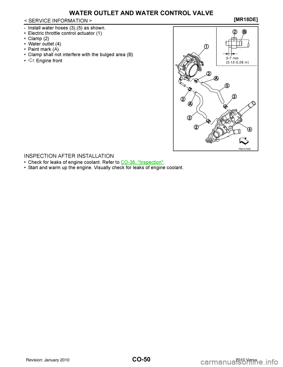
- Install water hoses (3),(5) as shown.
• Electric throttle control actuator (1)
• Clamp (2)
• Water outlet (4)
• Paint mark (A)
• Clamp shall not interfere with the bulged area (B)
• : Engine front
INSPECTION AFTER INSTALLATION
• Check for leaks of engine coolant. Refer to
CO-36, "Inspection".
• Start and warm up the engine. Visually check for leaks of engine coolant.
PBIC4703E
Revision: January 20102010 Versa
Page 1036 of 3745
CVT-3
DE
F
G H
I
J
K L
M A
B
CVT
N
O
P
N
CONSULT-III Refe
rence Value in Data Monitor
Mode ................................................................... ..
100
On Board Diagnosis Logic ....................................100
Possible Cause .....................................................100
DTC Confirmation Procedure ................................100
Wiring Diagram - CVT - SECPSV ....................... ..101
Diagnosis Procedure ........................................... ..102
Component Inspection ..........................................103
P0840 TRANSMISSION FLUID PRESSURE
SEN/SW A ........................................................
105
Description ............................................................105
CONSULT-III Reference Value in Data Monitor
Mode ................................................................... ..
105
On Board Diagnosis Logic ....................................105
Possible Cause .....................................................105
DTC Confirmation Procedure ................................105
Wiring Diagram - CVT - SECPS ............................106
Diagnosis Procedure .............................................107
P0841 TRANSMISSION FLUID PRESSURE
SEN/SW A ........................................................
109
Description ............................................................109
CONSULT-III Reference Value in Data Monitor
Mode ................................................................... ..
109
On Board Diagnosis Logic ....................................109
Possible Cause .....................................................109
DTC Confirmation Procedure ................................109
Diagnosis Procedure .............................................109
P0868 TRANSMISSION FLUID PRESSURE ...111
Description .......................................................... ..111
CONSULT-III Reference Value in Data Monitor
Mode ................................................................... ..
111
On Board Diagnosis Logic ....................................111
Possible Cause .....................................................111
DTC Confirmation Procedure ................................111
Diagnosis Procedure .............................................111
P1701 TCM .......................................................113
Description .......................................................... ..113
On Board Diagnosis Logic ....................................113
Possible Cause .....................................................113
DTC Confirmation Procedure ................................113
Wiring Diagram - CVT - POWER ..........................114
Diagnosis Procedure .............................................115
P1705 TP SENSOR ..........................................117
Description .......................................................... ..117
CONSULT-III Reference Value in Data Monitor
Mode ................................................................... ..
117
On Board Diagnosis Logic ....................................117
Possible Cause .....................................................117
DTC Confirmation Procedure ................................117
Diagnosis Procedure .............................................117
P1722 VEHICLE SPEED ..................................119
Description ............................................................119
CONSULT-III Reference Value in Data Monitor
Mode ................................................................... ..
119
On Board Diagnosis Logic ................................... ..119
Possible Cause ......................................................119
DTC Confirmation Procedure ................................119
Diagnosis Procedure .............................................119
P1723 SPEED SENSOR .................................121
Description .............................................................121
On Board Diagnosis Logic .....................................121
Possible Cause ......................................................121
DTC Confirmation Procedure ................................121
Diagnosis Procedure .............................................121
P1726 THROTTLE CONTROL SIGNAL .........123
Description .............................................................123
On Board Diagnosis Logic .....................................123
Possible Cause ......................................................123
DTC Confirmation Procedure ................................123
Diagnosis Procedure .............................................123
P1740 SELECT SOLENOID ...........................124
Description .............................................................124
CONSULT-III Reference Value in Data Monitor
Mode .................................................................... ..
124
On Board Diagnosis Logic .....................................124
Possible Cause ......................................................124
DTC Confirmation Procedure ................................124
Wiring Diagram - CVT - L/USSV ...........................125
Diagnosis Procedure .............................................126
Component Inspection ...........................................127
P1745 LINE PRESSURE CONTROL ..............128
Description .............................................................128
On Board Diagnosis Logic .....................................128
Possible Cause ......................................................128
DTC Confirmation Procedure ................................128
Diagnosis Procedure .............................................128
P1777 STEP MOTOR ......................................129
Description .............................................................129
CONSULT-III Reference Value in Data Monitor
Mode .................................................................... ..
129
On Board Diagnosis Logic .....................................129
Possible Cause ......................................................129
DTC Confirmation Procedure ................................129
Wiring Diagram - CVT - STM .................................130
Diagnosis Procedure .............................................131
Component Inspection ...........................................132
P1778 STEP MOTOR ......................................133
Description .............................................................133
CONSULT-III Reference Value in Data Monitor
Mode .................................................................... ..
133
On Board Diagnosis Logic .....................................133
Possible Cause ......................................................133
DTC Confirmation Procedure ................................133
Diagnosis Procedure .............................................134
OVERDRIVE CONTROL SWITCH ..................135
Description .............................................................135
Revision: January 20102010 Versa
Page 1038 of 3745
INDEX FOR DTCCVT-5
< SERVICE INFORMATION > [RE0F08B]
D
E
F
G H
I
J
K L
M A
B
CVT
N
O P
SERVICE INFORMATION
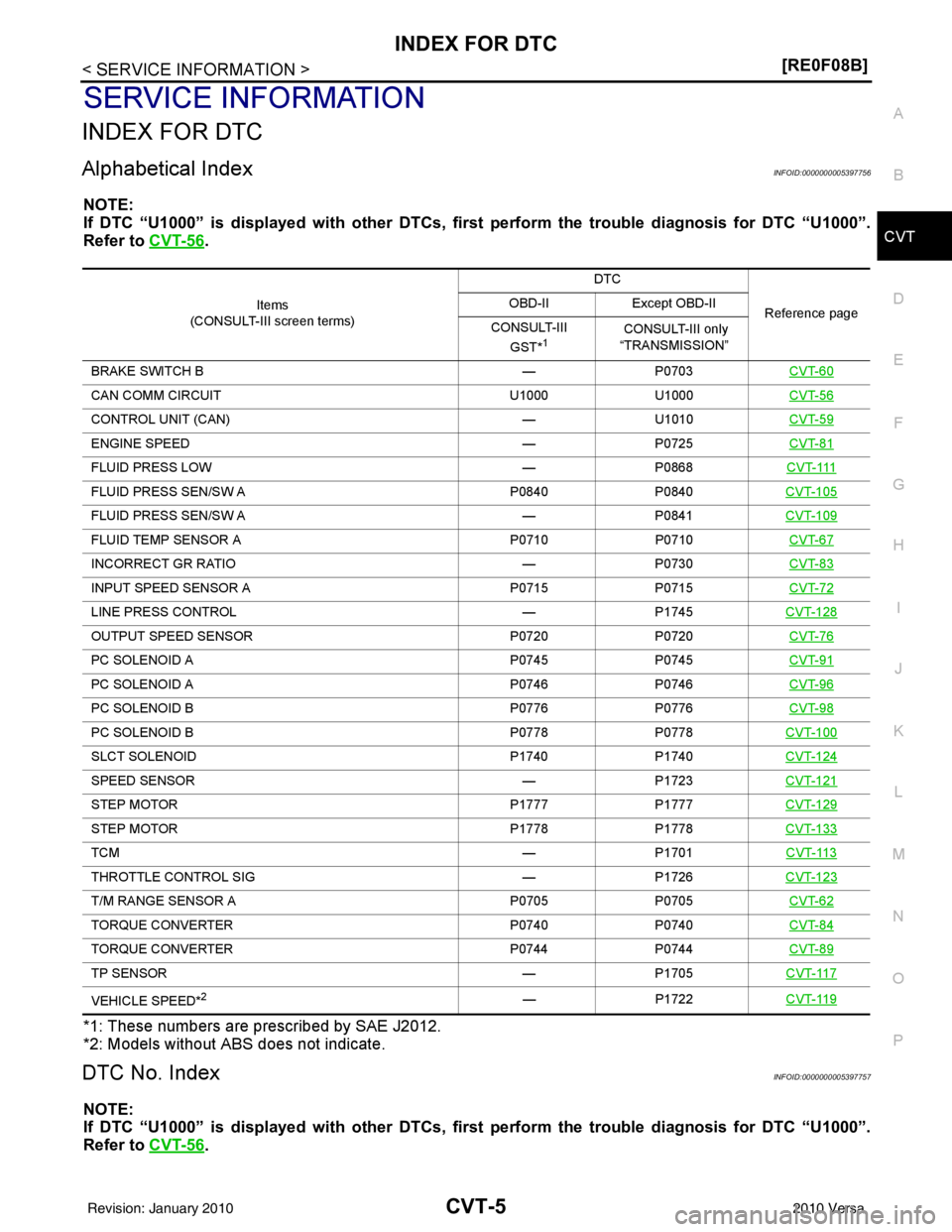
INDEX FOR DTC
Alphabetical IndexINFOID:0000000005397756
NOTE:
If DTC “U1000” is displayed with other DTCs, fi rst perform the trouble diagnosis for DTC “U1000”.
Refer to CVT-56
.
*1: These numbers are prescribed by SAE J2012.
*2: Models without ABS does not indicate.
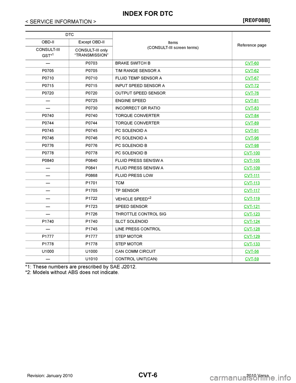
DTC No. IndexINFOID:0000000005397757
NOTE:
If DTC “U1000” is displayed with other DTCs, fi rst perform the trouble diagnosis for DTC “U1000”.
Refer to CVT-56
.
Items
(CONSULT-III screen terms) DTC
Reference page
OBD-II
Except OBD-II
CONSULT-III GST*
1 CONSULT-III only
“TRANSMISSION”
BRAKE SWITCH B —P0703 CVT-60
CAN COMM CIRCUIT U1000 U1000 CVT-56
CONTROL UNIT (CAN)—U1010 CVT-59
ENGINE SPEED —P0725 CVT-81
FLUID PRESS LOW —P0868C V T- 111
FLUID PRESS SEN/SW A P0840P0840CVT-105
FLUID PRESS SEN/SW A —P0841CVT-109
FLUID TEMP SENSOR A P0710P0710CVT-67
INCORRECT GR RATIO —P0730 CVT-83
INPUT SPEED SENSOR A P0715P0715CVT-72
LINE PRESS CONTROL —P1745CVT-128
OUTPUT SPEED SENSOR P0720P0720CVT-76
PC SOLENOID A P0745P0745CVT-91
PC SOLENOID A P0746P0746CVT-96
PC SOLENOID B P0776P0776CVT-98
PC SOLENOID B P0778P0778CVT-100
SLCT SOLENOID P1740P1740CVT-124
SPEED SENSOR —P1723CVT-121
STEP MOTOR P1777P1777CVT-129
STEP MOTOR P1778P1778CVT-133
TCM —P1701CVT-113
THROTTLE CONTROL SIG —P1726CVT-123
T/M RANGE SENSOR A P0705P0705CVT-62
TORQUE CONVERTER P0740P0740CVT-84
TORQUE CONVERTER P0744 P0744 CVT-89
TP SENSOR —P1705CVT-117
VEHICLE SPEED*2— P1722CVT-119
Revision: January 20102010 Versa
Page 1039 of 3745
CVT-6
< SERVICE INFORMATION >[RE0F08B]
INDEX FOR DTC
*1: These numbers are pr
escribed by SAE J2012.
*2: Models without ABS does not indicate.
DTC
Items
(CONSULT-III screen terms) Reference page
OBD-II
Except OBD-II
CONSULT-III GST*
1CONSULT-III only
“TRANSMISSION”
— P0703 BRAKE SWITCH B CVT-60
P0705P0705 T/M RANGE SENSOR A CVT-62
P0710P0710 FLUID TEMP SENSOR A CVT-67
P0715P0715 INPUT SPEED SENSOR A CVT-72
P0720P0720 OUTPUT SPEED SENSOR CVT-76
—P0725 ENGINE SPEED CVT-81
—P0730 INCORRECT GR RATIO CVT-83
P0740P0740 TORQUE CONVERTER CVT-84
P0744 P0744 TORQUE CONVERTER CVT-89
P0745P0745 PC SOLENOID A CVT-91
P0746P0746 PC SOLENOID A CVT-96
P0776P0776 PC SOLENOID B CVT-98
P0778P0778 PC SOLENOID B CVT-100
P0840P0840 FLUID PRESS SEN/SW A CVT-105
—P0841 FLUID PRESS SEN/SW A CVT-109
—P0868 FLUID PRESS LOW C V T- 111
—P1701 TCM CVT-113
—P1705 TP SENSOR CVT-117
—P1722
VEHICLE SPEED*2CVT-119
— P1723 SPEED SENSOR CVT-121
—P1726 THROTTLE CONTROL SIG CVT-123
P1740P1740 SLCT SOLENOID CVT-124
—P1745 LINE PRESS CONTROL CVT-128
P1777P1777 STEP MOTOR CVT-129
P1778P1778 STEP MOTOR CVT-133
U1000U1000 CAN COMM CIRCUIT CVT-56
—U1010 CONTROL UNIT(CAN) CVT-59
Revision: January 20102010 Versa
Page 1054 of 3745
CVT SYSTEMCVT-21
< SERVICE INFORMATION > [RE0F08B]
D
E
F
G H
I
J
K L
M A
B
CVT
N
O P
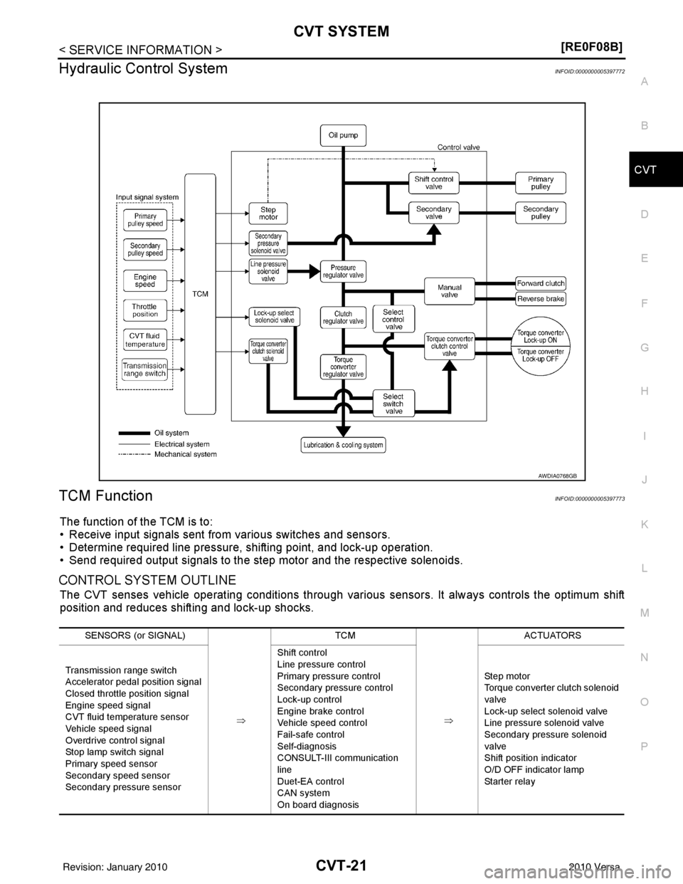
Hydraulic Control SystemINFOID:0000000005397772
TCM FunctionINFOID:0000000005397773
The function of the TCM is to:
• Receive input signals sent from various switches and sensors.
• Determine required line pressure, shifting point, and lock-up operation.
• Send required output signals to the step motor and the respective solenoids.
CONTROL SYSTEM OUTLINE
The CVT senses vehicle operating conditions through various sensors. It always controls the optimum shift
position and reduces shifting and lock-up shocks.
AWDIA0768GB
SENSORS (or SIGNAL)
⇒TCM
⇒ACTUATORS
Transmission range switch
Accelerator pedal position signal
Closed throttle position signal
Engine speed signal
CVT fluid temperature sensor
Vehicle speed signal
Overdrive control signal
Stop lamp switch signal
Primary speed sensor
Secondary speed sensor
Secondary pressure sensor Shift control
Line pressure control
Primary pressure control
Secondary pressure control
Lock-up control
Engine brake control
Vehicle speed control
Fail-safe control
Self-diagnosis
CONSULT-III co
mmunication
line
Duet-EA control
CAN system
On board diagnosis Step motor
Torque converter clutch solenoid
valve
Lock-up select solenoid valve
Line pressure solenoid valve
Secondary pressure solenoid
valve
Shift position indicator
O/D OFF indicator lamp
Starter relay
Revision: January 20102010 Versa
Page 1055 of 3745
CVT-22
< SERVICE INFORMATION >[RE0F08B]
CVT SYSTEM
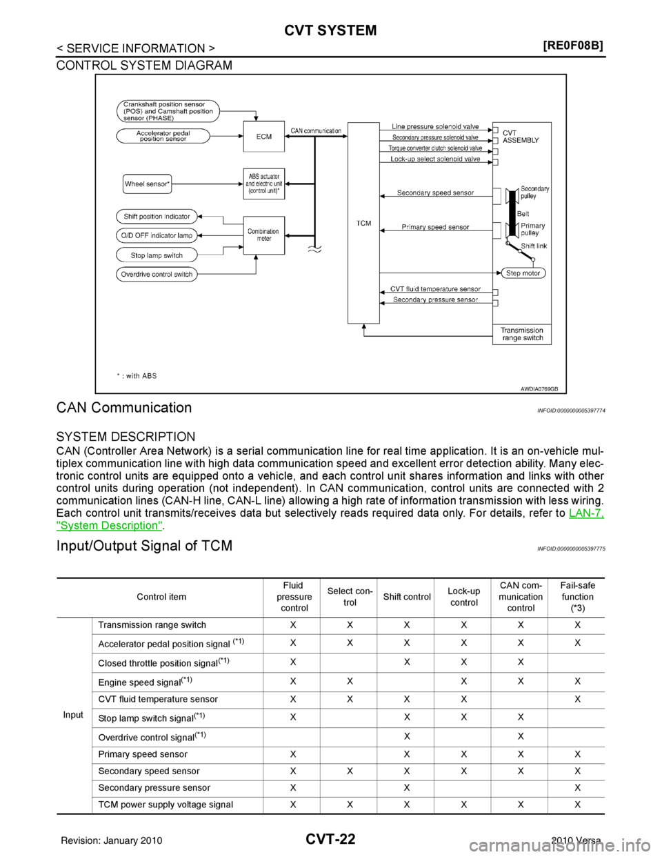
CONTROL SYSTEM DIAGRAM
CAN CommunicationINFOID:0000000005397774
SYSTEM DESCRIPTION
CAN (Controller Area Network) is a serial communication line for real time application. It is an on-vehicle mul-
tiplex communication line with high data communication s
peed and excellent error detection ability. Many elec-
tronic control units are equipped onto a vehicle, and each control unit shares information and links with other
control units during operation (not independent). In CA N communication, control units are connected with 2
communication lines (CAN-H line, CAN-L line) allowing a high rate of information transmission with less wiring.
Each control unit transmits/receives data but selectively reads required data only. For details, refer to LAN-7,
"System Description".
Input/Output Signal of TCMINFOID:0000000005397775
AWDIA0769GB
Control itemFluid
pressure control Select con-
trol Shift control Lock-up
control CAN com-
munication control Fail-safe
function (*3)
Input T
ra n sm is sio n r ang e s wit c h XXXXXX
Accelerator pedal position signal
(*1)XXXXXX
Closed throttle position signal
(*1)X XXX
Engine speed signal
(*1)XX XXX
CVT fluid temperature sensor XX XX X
Stop lamp switch signal
(*1)X XXX
Overdrive control signal
(*1)XX
Primary speed sensor X XXXX
Secondary speed sensor XXXXXX
Secondary pressure sensor XX X
T C M pow er s upp ly v olt a ge s ig n al XXXXXX
Revision: January 20102010 Versa
Page 1056 of 3745
CVT SYSTEMCVT-23
< SERVICE INFORMATION > [RE0F08B]
D
E
F
G H
I
J
K L
M A
B
CVT
N
O P
*1: Input by CAN communications.
*2: Output by CAN communications.
*3: If these input and output signals are different, the TCM triggers the fail-safe function.
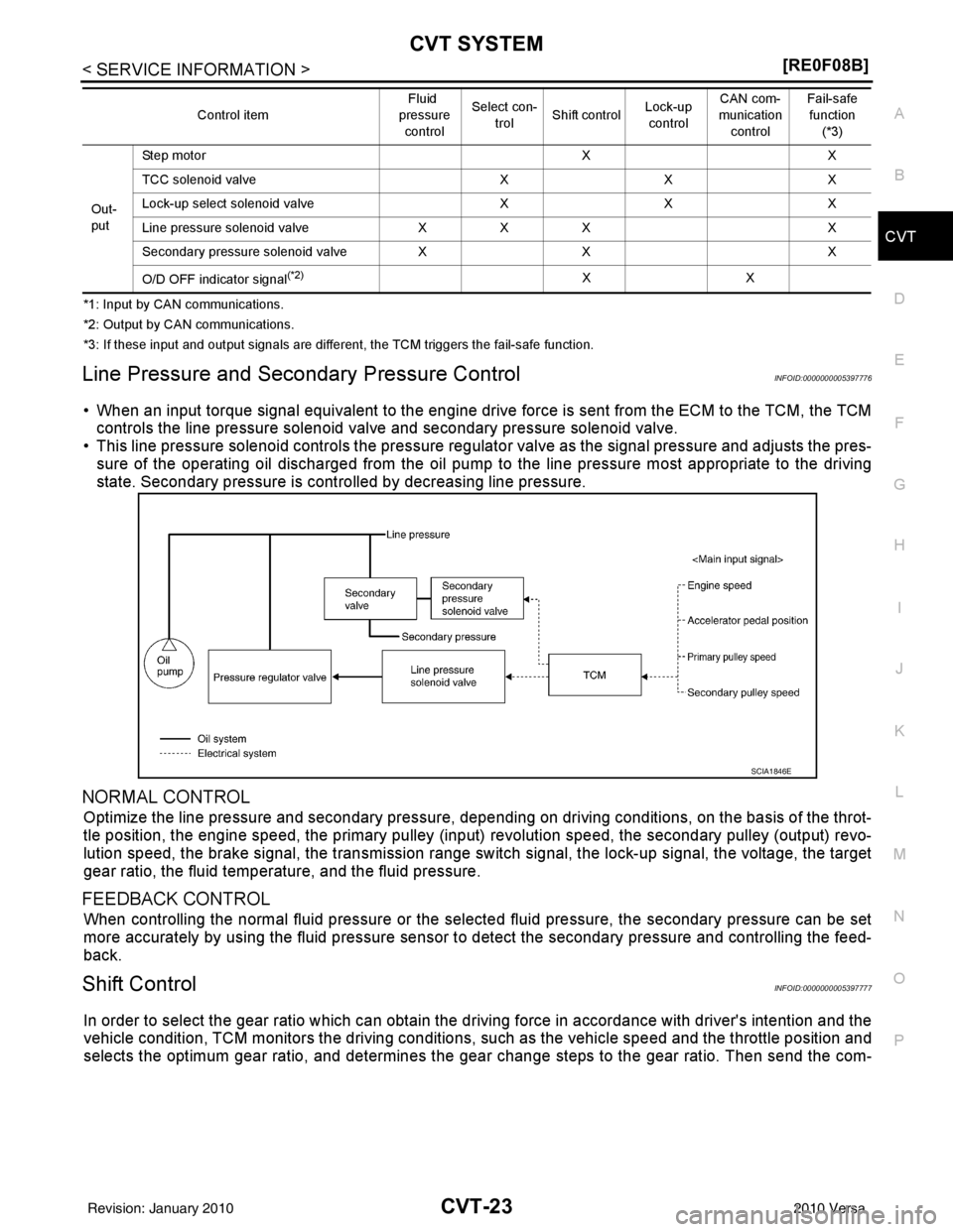
Line Pressure and Secondary Pressure ControlINFOID:0000000005397776
• When an input torque signal equivalent to the engine drive force is sent from the ECM to the TCM, the TCM
controls the line pressure solenoid valve and secondary pressure solenoid valve.
• This line pressure solenoid controls the pressure regulat or valve as the signal pressure and adjusts the pres-
sure of the operating oil discharged from the oil pump to the line pressure most appropriate to the driving
state. Secondary pressure is cont rolled by decreasing line pressure.
NORMAL CONTROL
Optimize the line pressure and secondary pressure, dependi ng on driving conditions, on the basis of the throt-
tle position, the engine speed, the primary pulley (input ) revolution speed, the secondary pulley (output) revo-
lution speed, the brake signal, the transmission range switch signal, the lock-up signal, the voltage, the target
gear ratio, the fluid temperat ure, and the fluid pressure.
FEEDBACK CONTROL
When controlling the normal fluid pressure or the sele cted fluid pressure, the secondary pressure can be set
more accurately by using the fluid pressure sensor to detect the secondary pressure and controlling the feed-
back.
Shift ControlINFOID:0000000005397777
In order to select the gear ratio which can obtain the dr iving force in accordance with driver's intention and the
vehicle condition, TCM monitors the driving conditions, such as the vehicle speed and the throttle position and
selects the optimum gear ratio, and determines the gear change steps to the gear ratio. Then send the com-
Out-
putSte p mo tor
XX
TCC solenoid valve XXX
Lock-up select solenoid valve XXX
Line pressure solenoid valve XXX X
Secondary pressure solenoid valve XX X
O/D OFF indicator signal
(*2)XX
Control item
Fluid
pressure
control Select con-
trol Shift control
Lock-up
control CAN com-
munication
control Fail-safe
function
(*3)
SCIA1846E
Revision: January 20102010 Versa
Page 1058 of 3745
CVT SYSTEMCVT-25
< SERVICE INFORMATION > [RE0F08B]
D
E
F
G H
I
J
K L
M A
B
CVT
N
O P
Lock-up and Select ControlINFOID:0000000005397778
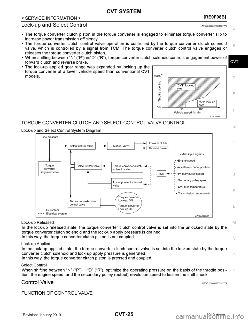
• The torque converter clutch piston in the torque conv erter is engaged to eliminate torque converter slip to
increase power transmission efficiency.
• The torque converter clutch control valve operation is controlled by the torque converter clutch solenoid
valve, which is controlled by a signal from TCM. The torque converter clutch control valve engages or
releases the torque converter clutch piston.
• When shifting between “N” (“P”) ⇒“D” (“R”), torque converter clutch solenoid controls engagement power of
forward clutch and reverse brake.
• The lock-up applied gear range was expanded by locking up the torque converter at a lower vehicle speed than conventional CVT
models.
TORQUE CONVERTER CLUTCH AND SELECT CONTROL VALVE CONTROL
Lock-up and Select Control System Diagram
Lock-up Released
In the lock-up released state, the torque converter clutch control valve is set into the unlocked state by the
torque converter clutch solenoid and the lock-up apply pressure is drained.
In this way, the torque converter clutch piston is not coupled.
Lock-up Applied
In the lock-up applied state, the torque converter clutch control valve is set into the locked state by the torque
converter clutch solenoid and lock-up apply pressure is generated.
In this way, the torque converter clutch piston is pressed and coupled.
Select Control
When shifting between “N” (“P”) ⇒“D” (“R”), optimize the operating pressure on the basis of the throttle posi-
tion, the engine speed, and the secondary pulley (out put) revolution speed to lessen the shift shock.
Control ValveINFOID:0000000005397779
FUNCTION OF CONTROL VALVE
SCIA1958E
AWDIA0778GB
Revision: January 20102010 Versa
Page 1077 of 3745
CVT-44
< SERVICE INFORMATION >[RE0F08B]
TROUBLE DIAGNOSIS
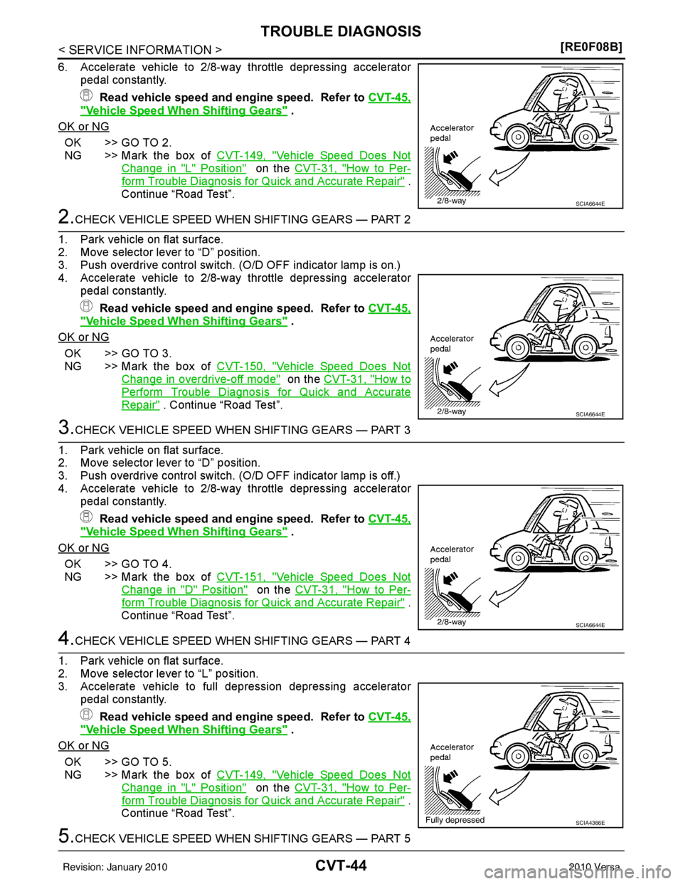
6. Accelerate vehicle to 2/8-way throttle depressing accelerator
pedal constantly.
Read vehicle speed and engine speed. Refer to CVT-45,
"Vehicle Speed When Shifting Gears" .
OK or NG
OK >> GO TO 2.
NG >> Mark the box of CVT-149, "
Vehicle Speed Does Not
Change in "L" Position" on the CVT-31, "How to Per-
form Trouble Diagnosis for Quick and Accurate Repair" .
Continue “Road Test”.
2.CHECK VEHICLE SPEED WHEN SHIFTING GEARS — PART 2
1. Park vehicle on flat surface.
2. Move selector lever to “D” position.
3. Push overdrive control switch. (O/D OFF indicator lamp is on.)
4. Accelerate vehicle to 2/8-way throttle depressing accelerator pedal constantly.
Read vehicle speed and engine speed. Refer to CVT-45,
"Vehicle Speed When Shifting Gears" .
OK or NG
OK >> GO TO 3.
NG >> Mark the box of CVT-150, "
Vehicle Speed Does Not
Change in overdrive-off mode" on the CVT-31, "How to
Perform Trouble Diagnosis for Quick and Accurate
Repair" . Continue “Road Test”.
3.CHECK VEHICLE SPEED WHEN SHIFTING GEARS — PART 3
1. Park vehicle on flat surface.
2. Move selector lever to “D” position.
3. Push overdrive control switch. (O/D OFF indicator lamp is off.)
4. Accelerate vehicle to 2/8-way throttle depressing accelerator pedal constantly.
Read vehicle speed and engine speed. Refer to CVT-45,
"Vehicle Speed When Shifting Gears" .
OK or NG
OK >> GO TO 4.
NG >> Mark the box of CVT-151, "
Vehicle Speed Does Not
Change in "D" Position" on the CVT-31, "How to Per-
form Trouble Diagnosis for Quick and Accurate Repair" .
Continue “Road Test”.
4.CHECK VEHICLE SPEED WHEN SHIFTING GEARS — PART 4
1. Park vehicle on flat surface.
2. Move selector lever to “L” position.
3. Accelerate vehicle to full depression depressing accelerator pedal constantly.
Read vehicle speed and engine speed. Refer to CVT-45,
"Vehicle Speed When Shifting Gears" .
OK or NG
OK >> GO TO 5.
NG >> Mark the box of CVT-149, "
Vehicle Speed Does Not
Change in "L" Position" on the CVT-31, "How to Per-
form Trouble Diagnosis for Quick and Accurate Repair" .
Continue “Road Test”.
5.CHECK VEHICLE SPEED WHEN SHIFTING GEARS — PART 5
SCIA6644E
SCIA6644E
SCIA6644E
SCIA4366E
Revision: January 20102010 Versa
Page 1085 of 3745
CVT-52
< SERVICE INFORMATION >[RE0F08B]
TROUBLE DIAGNOSIS
*1: Refer to CVT-28, "Malfunction Indicator Lamp (MIL)" .
*2: Models without ABS does not indicate.
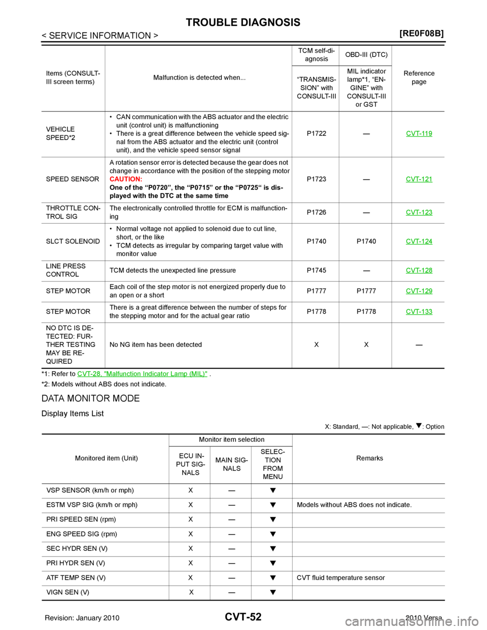
DATA MONITOR MODE
Display Items List
X: Standard, —: Not applicable, : Option
VEHICLE
SPEED*2• CAN communication with the
ABS actuator and the electric
unit (control unit) is malfunctioning
• There is a great difference between the vehicle speed sig-
nal from the ABS actuator and the electric unit (control
unit), and the vehicle speed sensor signal P1722
—CVT-119
SPEED SENSOR A rotation sensor error is detected because the gear does not
change in accordance with the position of the stepping motor
CAUTION:
One of the “P0720”, the “P0715” or the “P0725“ is dis-
played with the DTC at the same time P1723
—CVT-121
THROTTLE CON-
TROL SIG The electronically controlled throttle for ECM is malfunction-
ing
P1726
—CVT-123
SLCT SOLENOID • Normal voltage not applied to solenoid due to cut line,
short, or the like
• TCM detects as irregular by comparing target value with
monitor value P1740 P1740
CVT-124
LINE PRESS
CONTROLTCM detects the unexpected line pressure
P1745—CVT-128
STEP MOTOR Each coil of the step motor is not energized properly due to
an open or a short P1777 P1777
CVT-129
STEP MOTORThere is a great difference between the number of steps for
the stepping motor and for the actual gear ratio
P1778 P1778
CVT-133
NO DTC IS DE-
TECTED: FUR-
THER TESTING
MAY BE RE-
QUIREDNo NG item has been detected
XX —
Items (CONSULT-
III screen terms)
Malfunction is detected when... TCM self-di-
agnosis OBD-III (DTC)
Reference page
“TRANSMIS-
SION” with
CONSULT-III MIL indicator
lamp*1, “EN-
GINE” with
CONSULT-III
or GST
Monitored item (Unit) Monitor item selection
Remarks
ECU IN-
PUT SIG-
NALS MAIN SIG-
NALS SELEC-
TION
FROM
MENU
VSP SENSOR (km/h or mph) X—
ESTM VSP SIG (km/h or mph) X— Models without ABS does not indicate.
PRI SPEED SEN (rpm) X—
ENG SPEED SIG (rpm) X—
SEC HYDR SEN (V) X—
PRI HYDR SEN (V) X—
ATF TEMP SEN (V) X— CVT fluid temperature sensor
VIGN SEN (V) X—
Revision: January 20102010 Versa