steering wheel NISSAN TIIDA 2010 Service Workshop Manual
[x] Cancel search | Manufacturer: NISSAN, Model Year: 2010, Model line: TIIDA, Model: NISSAN TIIDA 2010Pages: 3745, PDF Size: 73.67 MB
Page 893 of 3745
PRECAUTIONSBRC-3
< SERVICE INFORMATION > [ABS]
C
D
E
G H
I
J
K L
M A
B
BRC
N
O P
SERVICE INFORMATION
PRECAUTIONS
Precaution for Supplemental Restraint System (SRS) "AIR BAG" and "SEAT BELT
PRE-TENSIONER"
INFOID:0000000005397020
The Supplemental Restraint System such as “AIR BAG” and “SEAT BELT PRE-TENSIONER”, used along
with a front seat belt, helps to reduce the risk or severi ty of injury to the driver and front passenger for certain
types of collision. This system includes seat belt switch inputs and dual stage front air bag modules. The SRS
system uses the seat belt switches to determine the front air bag deployment, and may only deploy one front
air bag, depending on the severity of a collision and w hether the front occupants are belted or unbelted.
Information necessary to service the system safely is included in the SRS and SB section of this Service Man-
ual.
WARNING:
• To avoid rendering the SRS inoper ative, which could increase the risk of personal injury or death in
the event of a collision which would result in air bag inflation, all maintenance must be performed by
an authorized NISSAN/INFINITI dealer.
• Improper maintenance, including in correct removal and installation of the SRS can lead to personal
injury caused by unintentional act ivation of the system. For removal of Spiral Cable and Air Bag
Module, see the SRS section.
• Do not use electrical test equipm ent on any circuit related to the SRS unless instructed to in this
Service Manual. SRS wiring harnesses can be identi fied by yellow and/or orange harnesses or har-
ness connectors.
PRECAUTIONS WHEN USING POWER TOOLS (AIR OR ELECTRIC) AND HAMMERS
WARNING:
• When working near the Airbag Diagnosis Sensor Un it or other Airbag System sensors with the Igni-
tion ON or engine running, DO NOT use air or el ectric power tools or strike near the sensor(s) with a
hammer. Heavy vibration could activate the sensor( s) and deploy the air bag(s), possibly causing
serious injury.
• When using air or electric power tools or hammers, always switch the Ignition OFF, disconnect the battery, and wait at least 3 minutes before performing any service.
Precaution Necessary for Steering Wheel Rotation After Battery Disconnect
INFOID:0000000006044767
NOTE:
• This Procedure is applied only to models with Intelligent Key system and NATS (NISSAN ANTI-THEFT SYS-
TEM).
• Remove and install all control units after disconnecti ng both battery cables with the ignition knob in the
″ LOCK ″ position.
• Always use CONSULT-III to perform self-diagnosis as a part of each function inspection after finishing work.
If DTC is detected, perform trouble diagnosis according to self-diagnostic results.
For models equipped with the Intelligent Key system and NATS , an electrically controlled steering lock mech-
anism is adopted on the key cylinder.
For this reason, if the battery is disconnected or if the battery is discharged, the steering wheel will lock and
steering wheel rotation will become impossible.
If steering wheel rotation is required when battery power is interrupted, follow the procedure below before
starting the repair operation.
OPERATION PROCEDURE
1. Connect both battery cables. NOTE:
Supply power using jumper cables if battery is discharged.
2. Use the Intelligent Key or mechanical key to turn the ignition switch to the ″ACC ″ position. At this time, the
steering lock will be released.
3. Disconnect both battery cables. The steering lock will remain released and the steering wheel can be
rotated.
4. Perform the necessary repair operation.
Revision: January 20102010 Versa
Page 929 of 3745
PRECAUTIONSBRC-39
< SERVICE INFORMATION > [VDC/TCS/ABS]
C
D
E
G H
I
J
K L
M A
B
BRC
N
O P
SERVICE INFORMATION
PRECAUTIONS
Precaution for Supplemental Restraint System (SRS) "AIR BAG" and "SEAT BELT
PRE-TENSIONER"
INFOID:0000000005612135
The Supplemental Restraint System such as “AIR BAG” and “SEAT BELT PRE-TENSIONER”, used along
with a front seat belt, helps to reduce the risk or severi ty of injury to the driver and front passenger for certain
types of collision. This system includes seat belt switch inputs and dual stage front air bag modules. The SRS
system uses the seat belt switches to determine the front air bag deployment, and may only deploy one front
air bag, depending on the severity of a collision and w hether the front occupants are belted or unbelted.
Information necessary to service the system safely is included in the SRS and SB section of this Service Man-
ual.
WARNING:
• To avoid rendering the SRS inoper ative, which could increase the risk of personal injury or death in
the event of a collision which would result in air bag inflation, all maintenance must be performed by
an authorized NISSAN/INFINITI dealer.
• Improper maintenance, including in correct removal and installation of the SRS can lead to personal
injury caused by unintentional act ivation of the system. For removal of Spiral Cable and Air Bag
Module, see the SRS section.
• Do not use electrical test equipm ent on any circuit related to the SRS unless instructed to in this
Service Manual. SRS wiring harnesses can be identi fied by yellow and/or orange harnesses or har-
ness connectors.
PRECAUTIONS WHEN USING POWER TOOLS (AIR OR ELECTRIC) AND HAMMERS
WARNING:
• When working near the Airbag Diagnosis Sensor Un it or other Airbag System sensors with the Igni-
tion ON or engine running, DO NOT use air or el ectric power tools or strike near the sensor(s) with a
hammer. Heavy vibration could activate the sensor( s) and deploy the air bag(s), possibly causing
serious injury.
• When using air or electric power tools or hammers, always switch the Ignition OFF, disconnect the battery, and wait at least 3 minutes before performing any service.
Precaution Necessary for Steering Wheel Rotation After Battery Disconnect
INFOID:0000000005976825
NOTE:
• This Procedure is applied only to models with Intelligent Key system and NATS (NISSAN ANTI-THEFT SYS-
TEM).
• Remove and install all control units after disconnecti ng both battery cables with the ignition knob in the
″ LOCK ″ position.
• Always use CONSULT-III to perform self-diagnosis as a part of each function inspection after finishing work.
If DTC is detected, perform trouble diagnosis according to self-diagnostic results.
For models equipped with the Intelligent Key system and NATS , an electrically controlled steering lock mech-
anism is adopted on the key cylinder.
For this reason, if the battery is disconnected or if the battery is discharged, the steering wheel will lock and
steering wheel rotation will become impossible.
If steering wheel rotation is required when battery power is interrupted, follow the procedure below before
starting the repair operation.
OPERATION PROCEDURE
1. Connect both battery cables. NOTE:
Supply power using jumper cables if battery is discharged.
2. Use the Intelligent Key or mechanical key to turn the ignition switch to the ″ACC ″ position. At this time, the
steering lock will be released.
3. Disconnect both battery cables. The steering lock will remain released and the steering wheel can be
rotated.
4. Perform the necessary repair operation.
Revision: January 20102010 Versa
Page 930 of 3745
BRC-40
< SERVICE INFORMATION >[VDC/TCS/ABS]
PRECAUTIONS
5. When the repair work is completed, return the ignition switch to the
″LOCK ″ position before connecting
the battery cables. (At this time, the steering lock mechanism will engage.)
6. Perform a self-diagnosis check of a ll control units using CONSULT-III.
Precaution for Brake SystemINFOID:0000000005612137
CAUTION:
• Refer to MA-14, "
Fluids and Lubricants" for recommended brake fluid.
• Never reuse drained brake fluid.
• Be careful not to splash brake fluid on painted areas; it may cause paint damage. If brake fluid is
splashed on painted areas, wash it away with water immediately.
• To clean or wash all parts of master cylin der and disc brake caliper, use clean brake fluid.
• Never use mineral oils such as gasoline or kerosene. They will ruin rubber parts of the hydraulic sys-
tem.
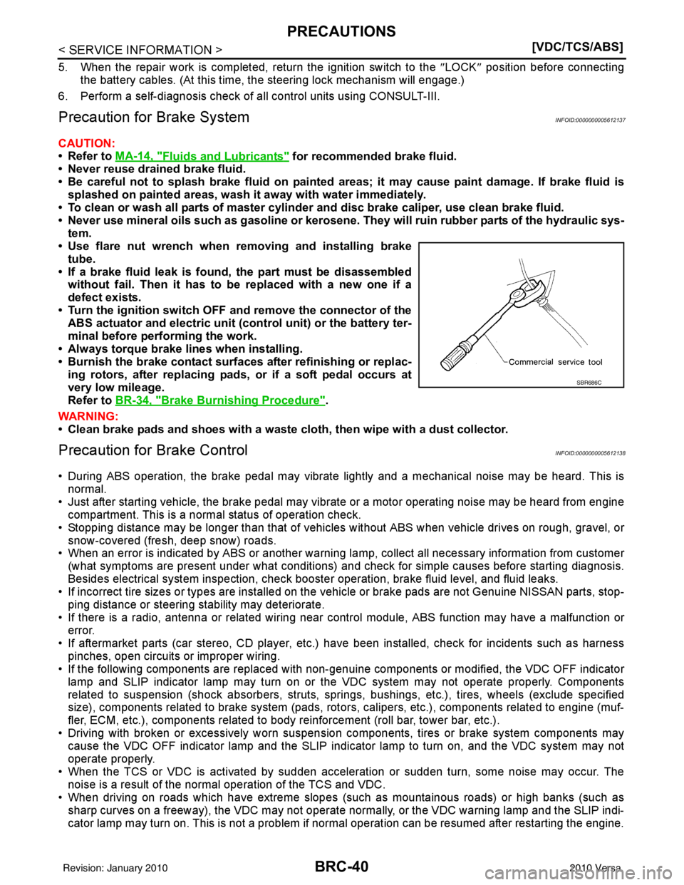
• Use flare nut wrench when removing and installing brake
tube.
• If a brake fluid leak is found, the part must be disassembled without fail. Then it has to be replaced with a new one if a
defect exists.
• Turn the ignition switch OFF an d remove the connector of the
ABS actuator and electric unit (c ontrol unit) or the battery ter-
minal before performing the work.
• Always torque brake lines when installing.
• Burnish the brake contact surf aces after refinishing or replac-
ing rotors, after replacing pads, or if a soft pedal occurs at
very low mileage.
Refer to BR-34, "
Brake Burnishing Procedure".
WARNING:
• Clean brake pads and shoes with a waste cloth, then wipe with a dust collector.
Precaution for Brake ControlINFOID:0000000005612138
• During ABS operation, the brake pedal may vibrate lightly and a mechanical noise may be heard. This is
normal.
• Just after starting vehicle, the brake pedal may vibrate or a motor operating noise may be heard from engine compartment. This is a normal status of operation check.
• Stopping distance may be longer than that of vehicles without ABS when vehicle drives on rough, gravel, or
snow-covered (fresh, deep snow) roads.
• When an error is indicated by ABS or another warning la mp, collect all necessary information from customer
(what symptoms are present under what conditions) and check for simple causes before starting diagnosis.
Besides electrical system inspection, check booste r operation, brake fluid level, and fluid leaks.
• If incorrect tire sizes or types are installed on the v ehicle or brake pads are not Genuine NISSAN parts, stop-
ping distance or steering stability may deteriorate.
• If there is a radio, antenna or related wiring near control module, ABS function may have a malfunction or
error.
• If aftermarket parts (car stereo, CD player, etc.) have been installed, check for incidents such as harness
pinches, open circuits or improper wiring.
• If the following components are replaced with non-genuine components or modified, the VDC OFF indicator
lamp and SLIP indicator lamp may turn on or the VDC system may not operate properly. Components
related to suspension (shock absorbers, struts, spri ngs, bushings, etc.), tires, wheels (exclude specified
size), components related to brake system (pads, rotors , calipers, etc.), components related to engine (muf-
fler, ECM, etc.), components related to body reinforcement (roll bar, tower bar, etc.).
• Driving with broken or excessively worn suspension components, tires or brake system components may cause the VDC OFF indicator lamp and the SLIP indi cator lamp to turn on, and the VDC system may not
operate properly.
• When the TCS or VDC is activated by sudden accele ration or sudden turn, some noise may occur. The
noise is a result of the normal operation of the TCS and VDC.
• When driving on roads which have extreme slopes (such as mountainous roads) or high banks (such as
sharp curves on a freeway), the VDC may not operate nor mally, or the VDC warning lamp and the SLIP indi-
cator lamp may turn on. This is not a problem if normal operation can be resumed after restarting the engine.
SBR686C
Revision: January 20102010 Versa
Page 934 of 3745
BRC-44
< SERVICE INFORMATION >[VDC/TCS/ABS]
SYSTEM DESCRIPTION
TCS Function
INFOID:0000000005612145
• Spinning of the drive wheels is detected by the A BS/TCS/VDC control unit using inputs from the wheel
speed sensors. If wheel spin occurs, the drive wheel right and left brake fluid pressure control and engine
fuel cut are conducted while the throttle value is restricted to reduce the engine torque and decrease the
amount of wheel spin. In addition, the throttle openi ng is controlled to achieve the optimum engine torque.
• Depending on road condition, the vehicle may have a sluggish feel. This is normal, because optimum trac- tion has the highest priority during TCS operation.
• TCS may be activated during sudden vehicle acceleration, wide open throttle acceleration, sudden transmis- sion shifts or when the vehicle is driven on a road with a varying surface friction coefficient.
• The SLIP indicator lamp flashes to inform the driver of TCS operation.
VDC FunctionINFOID:0000000005612146
• In addition to the ABS/TCS function, the driver steering amount and brake operation amount are detected
from the steering angle sensor, and the vehicle's drivi ng status (amount of under steering/over steering) is
determined using inputs from the yaw rate/side/decel G sensor, wheel speed sensors, etc. and this informa-
tion is used to improve vehicle stability by cont rolling the braking and engine torque application to the
wheels.
• The SLIP indicator lamp flashes to inform the driver of VDC operation.
• During VDC operation, the vehicle body and brake pedal may vibrate lightly and a mechanical noise may be
heard. This is normal.
• The ABS warning lamp, VDC OFF indicator lamp and SLIP indicator lamp may turn on when the vehicle is
subject to strong shaking or large vibration, such as when the vehicle is on a turn table or a ship while the
engine is running or steep slope. In this case, rest art the engine on a normal road and if the ABS warning
lamp, VDC OFF indicator lamp and SLIP indicator lamp turn off, there is no problem.
Wheel SensorsINFOID:0000000005612147
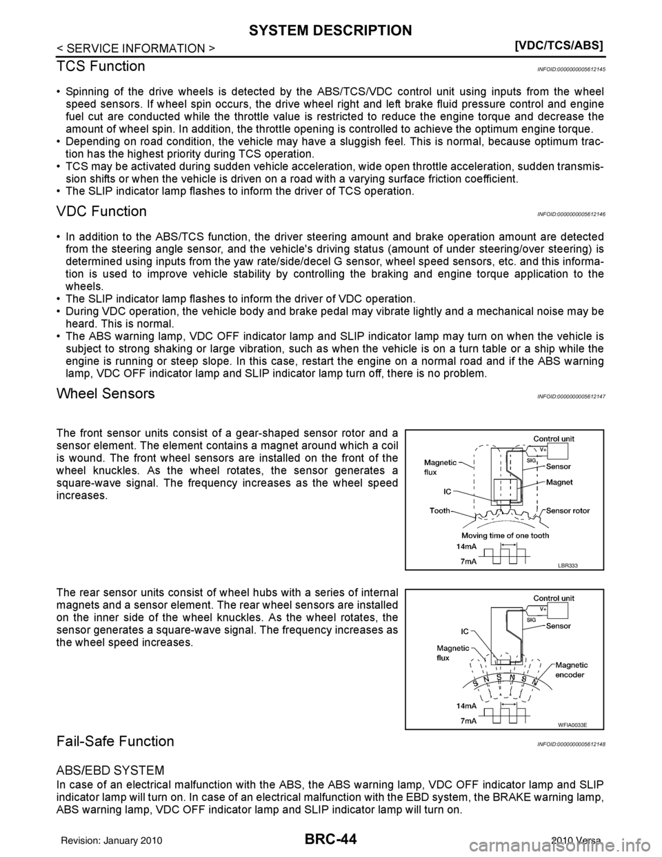
The front sensor units consist of a gear-shaped sensor rotor and a
sensor element. The element contains a magnet around which a coil
is wound. The front wheel sensors are installed on the front of the
wheel knuckles. As the wheel rotates, the sensor generates a
square-wave signal. The frequency in creases as the wheel speed
increases.
The rear sensor units consist of w heel hubs with a series of internal
magnets and a sensor element. The rear wheel sensors are installed
on the inner side of the wheel knuckles. As the wheel rotates, the
sensor generates a square-wave signal. The frequency increases as
the wheel speed increases.
Fail-Safe FunctionINFOID:0000000005612148
ABS/EBD SYSTEM
In case of an electrical malfunction with the ABS, t he ABS warning lamp, VDC OFF indicator lamp and SLIP
indicator lamp will turn on. In case of an electrical malfunction with the EBD system, the BRAKE warning lamp,
ABS warning lamp, VDC OFF indicator lamp and SLIP indicator lamp will turn on.
LBR333
WFIA0033E
Revision: January 20102010 Versa
Page 941 of 3745
TROUBLE DIAGNOSISBRC-51
< SERVICE INFORMATION > [VDC/TCS/ABS]
C
D
E
G H
I
J
K L
M A
B
BRC
N
O P
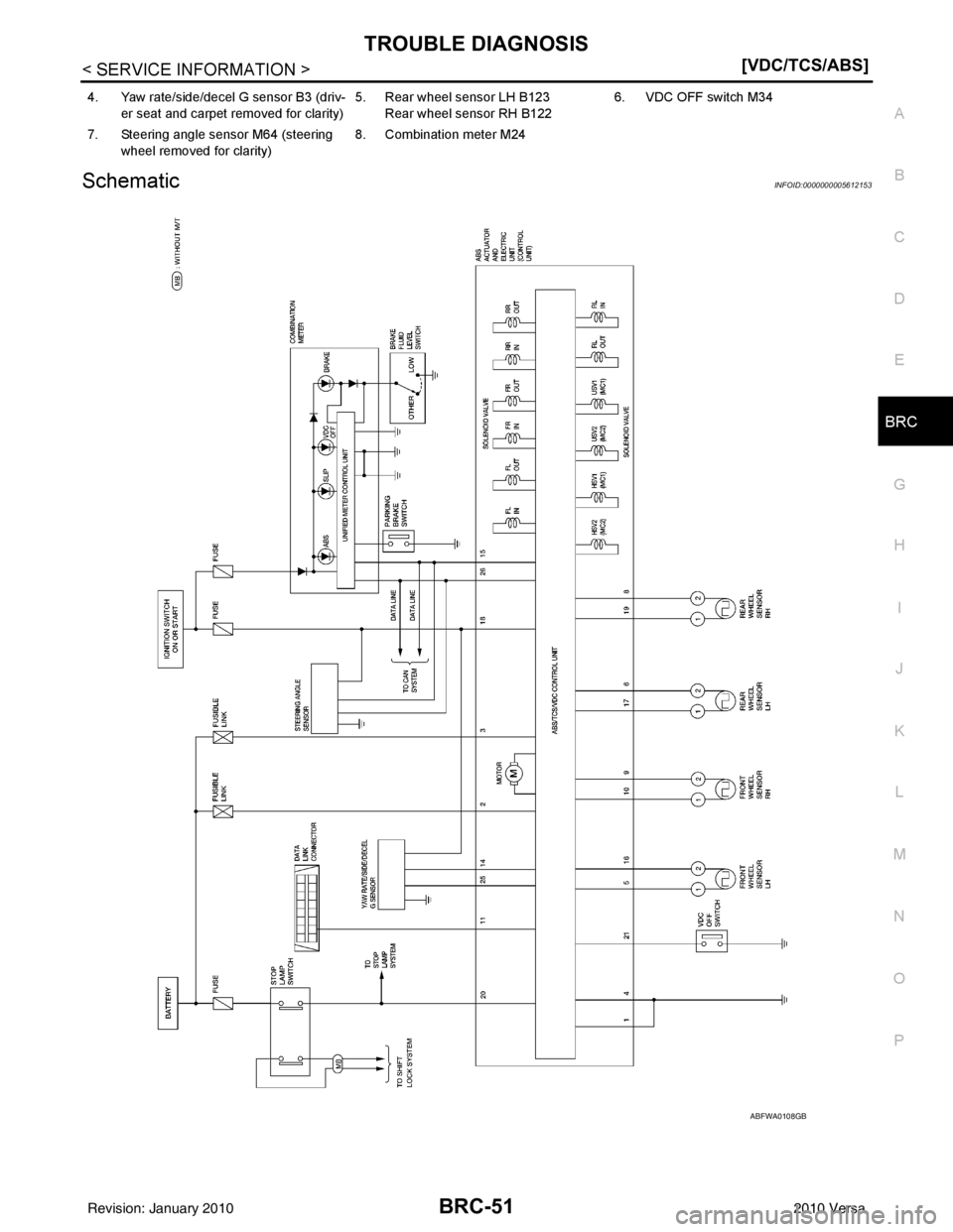
SchematicINFOID:0000000005612153
4. Yaw rate/side/decel G sensor B3 (driv- er seat and carpet removed for clarity) 5. Rear wheel sensor LH B123
Rear wheel sensor RH B122 6. VDC OFF switch M34
7. Steering angle sensor M64 (steering wheel removed for clarity) 8. Combination meter M24
ABFWA0108GB
Revision: January 20102010 Versa
Page 949 of 3745
TROUBLE DIAGNOSISBRC-59
< SERVICE INFORMATION > [VDC/TCS/ABS]
C
D
E
G H
I
J
K L
M A
B
BRC
N
O P
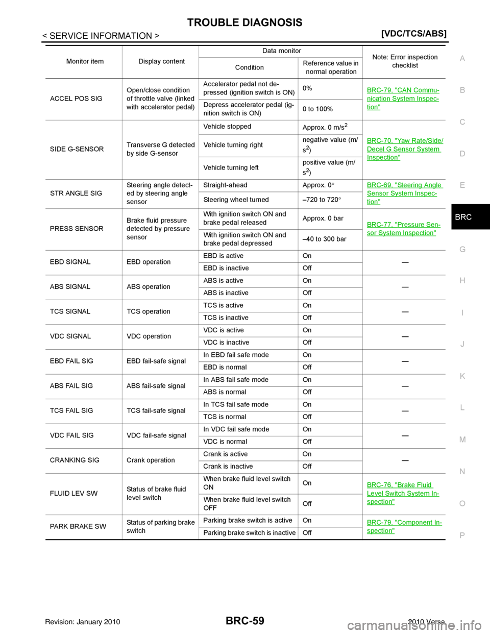
ACCEL POS SIG Open/close condition
of throttle valve (linked
with accelerator pedal)Accelerator pedal not de-
pressed (ignition switch is ON)
0%
BRC-79, "
CAN Commu-
nication System Inspec-
tion"Depress accelerator pedal (ig-
nition switch is ON) 0 to 100%
SIDE G-SENSOR Transverse G detected
by side G-sensorVehicle stopped
Approx. 0 m/s
2
BRC-70, "Yaw Rate/Side/
Decel G Sensor System
Inspection"
Vehicle turning rightnegative value (m/
s2)
Vehicle turning left positive value (m/
s
2)
STR ANGLE SIG Steering angle detect-
ed by steering angle
sensorStraight-ahead
Approx. 0°BRC-69, "
Steering Angle
Sensor System Inspec-
tion"Steering wheel turned –720 to 720 °
PRESS SENSOR Brake fluid pressure
detected by pressure
sensorWith ignition switch ON and
brake pedal released
Approx. 0 bar
BRC-77, "
Pressure Sen-
sor System Inspection"With ignition switch ON and
brake pedal depressed –40 to 300 bar
EBD SIGNAL EBD operation EBD is active
On
—
EBD is inactive Off
ABS SIGNAL ABS operationABS is active
On
—
ABS is inactive Off
TCS SIGNAL TCS operationTCS is active
On
—
TCS is inactive Off
VDC SIGNAL VDC operationVDC is active
On
—
VDC is inactive Off
EBD FAIL SIG EBD fail-safe signal In EBD fail safe mode On
—
EBD is normal Off
ABS FAIL SIG ABS fail-safe signal In ABS fail safe mode
On
—
ABS is normal Off
TCS FAIL SIG TCS fail-safe signal In TCS fail safe mode
On
—
TCS is normal Off
VDC FAIL SIG VDC fail-safe signal In VDC fail safe mode On
—
VDC is normal Off
CRANKING SIG Crank operation Crank is active
On
—
Crank is inactive Off
FLUID LEV SW Status of brake fluid
level switchWhen brake fluid level switch
ON
On
BRC-76, "
Brake Fluid
Level Switch System In-
spection"When brake fluid level switch
OFF Off
PARK BRAKE SW Status of parking brake
switchParking brake switch is active On
BRC-79, "
Component In-
spection"Parking brake switch is inactive Off
Monitor item Display content
Data monitor
Note: Error inspection
checklist
Condition Reference value in
normal operation
Revision: January 20102010 Versa
Page 952 of 3745
BRC-62
< SERVICE INFORMATION >[VDC/TCS/ABS]
TROUBLE DIAGNOSIS
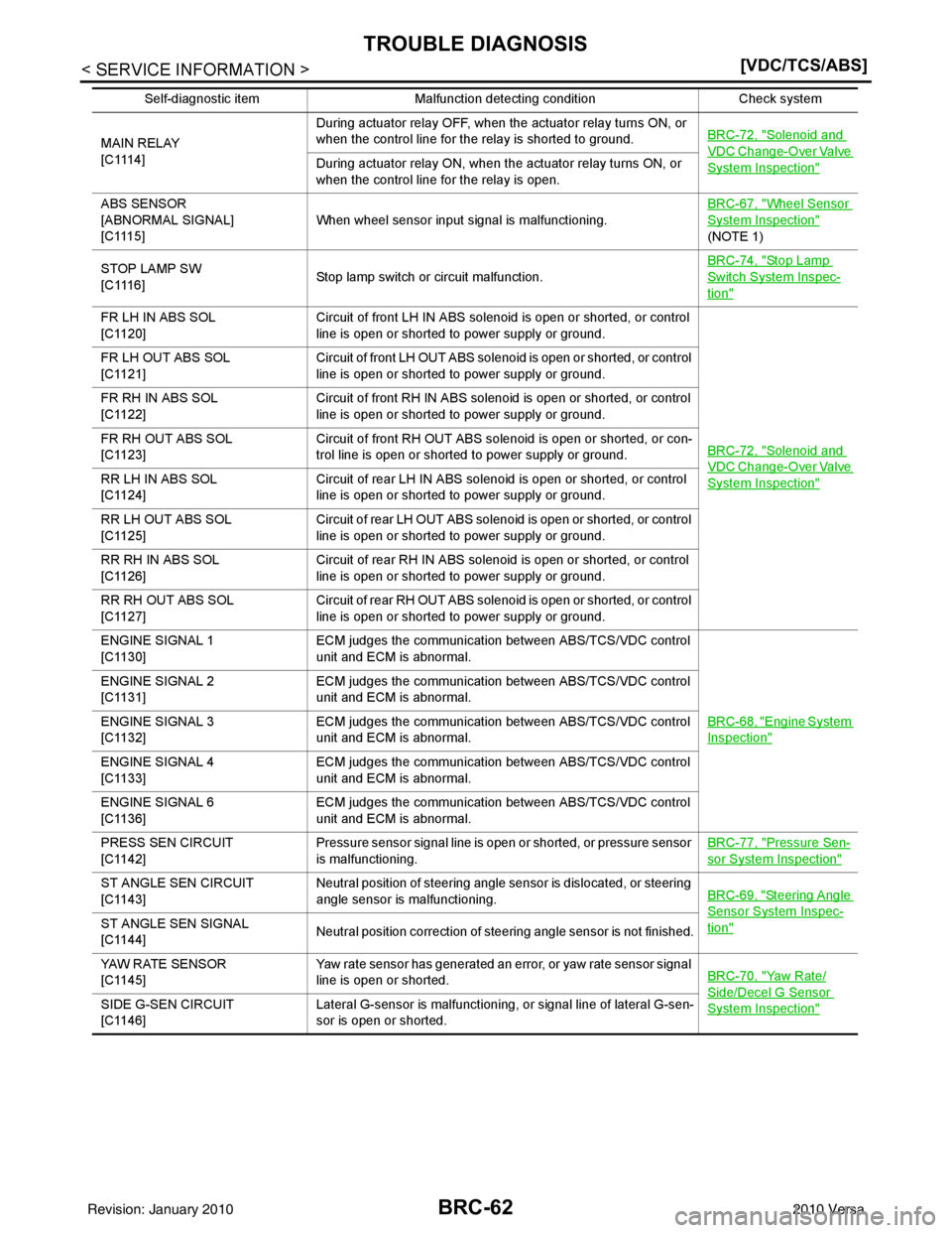
MAIN RELAY
[ C 111 4 ]During actuator relay OFF, when the actuator relay turns ON, or
when the control line for the relay is shorted to ground.
BRC-72, "Solenoid and
VDC Change-Over Valve
System Inspection"During actuator relay ON, when the actuator relay turns ON, or
when the control line for the relay is open.
ABS SENSOR
[ABNORMAL SIGNAL]
[ C 111 5 ] When wheel sensor input signal is malfunctioning. BRC-67, "
Wheel Sensor
System Inspection"
(NOTE 1)
STOP LAMP SW
[ C 111 6 ] Stop lamp switch or circuit malfunction. BRC-74, "
Stop Lamp
Switch System Inspec-
tion"
FR LH IN ABS SOL
[C1120]
Circuit of front LH IN ABS solenoid
is open or shorted, or control
line is open or shorted to power supply or ground.
BRC-72, "
Solenoid and
VDC Change-Over Valve
System Inspection"
FR LH OUT ABS SOL
[C1121]Circuit of front LH OUT ABS solenoid is open or shorted, or control
line is open or shorted to power supply or ground.
FR RH IN ABS SOL
[C1122] Circuit of front RH IN ABS solenoid is open or shorted, or control
line is open or shorted to power supply or ground.
FR RH OUT ABS SOL
[C1123] Circuit of front RH OUT ABS solenoid is open or shorted, or con-
trol line is open or shorted to power supply or ground.
RR LH IN ABS SOL
[C1124] Circuit of rear LH IN ABS solenoid
is open or shorted, or control
line is open or shorted to power supply or ground.
RR LH OUT ABS SOL
[C1125] Circuit of rear LH OUT ABS solenoid is open or shorted, or control
line is open or shorted to power supply or ground.
RR RH IN ABS SOL
[C1126] Circuit of rear RH IN ABS solenoid
is open or shorted, or control
line is open or shorted to power supply or ground.
RR RH OUT ABS SOL
[C1127] Circuit of rear RH OUT ABS solenoid is open or shorted, or control
line is open or shorted to power supply or ground.
ENGINE SIGNAL 1
[C1130] ECM judges th
e communication between ABS/TCS/VDC control
unit and ECM is abnormal.
BRC-68, "
Engine System
Inspection"
ENGINE SIGNAL 2
[C1131]ECM judges th
e communication between ABS/TCS/VDC control
unit and ECM is abnormal.
ENGINE SIGNAL 3
[C1132] ECM judges th
e communication between ABS/TCS/VDC control
unit and ECM is abnormal.
ENGINE SIGNAL 4
[C1133] ECM judges th
e communication between ABS/TCS/VDC control
unit and ECM is abnormal.
ENGINE SIGNAL 6
[C1136] ECM judges th
e communication between ABS/TCS/VDC control
unit and ECM is abnormal.
PRESS SEN CIRCUIT
[C1142] Pressure sensor signal line is open or shorted, or pressure sensor
is malfunctioning. BRC-77, "
Pressure Sen-
sor System Inspection"
ST ANGLE SEN CIRCUIT
[C1143]Neutral position of steering angle sensor is dislocated, or steering
angle sensor is malfunctioning.
BRC-69, "Steering Angle
Sensor System Inspec-
tion"ST ANGLE SEN SIGNAL
[C1144]Neutral position correction of steering angle sensor is not finished.
YAW RATE SENSOR
[C1145] Yaw rate sensor has generated an error, or yaw rate sensor signal
line is open or shorted.
BRC-70, "
Yaw Rate/
Side/Decel G Sensor
System Inspection"SIDE G-SEN CIRCUIT
[C1146]Lateral G-sensor is malfunctioning, or signal line of lateral G-sen-
sor is open or shorted.
Self-diagnostic item Malfunction detecting condition Check system
Revision: January 20102010 Versa
Page 953 of 3745
TROUBLE DIAGNOSISBRC-63
< SERVICE INFORMATION > [VDC/TCS/ABS]
C
D
E
G H
I
J
K L
M A
B
BRC
N
O P
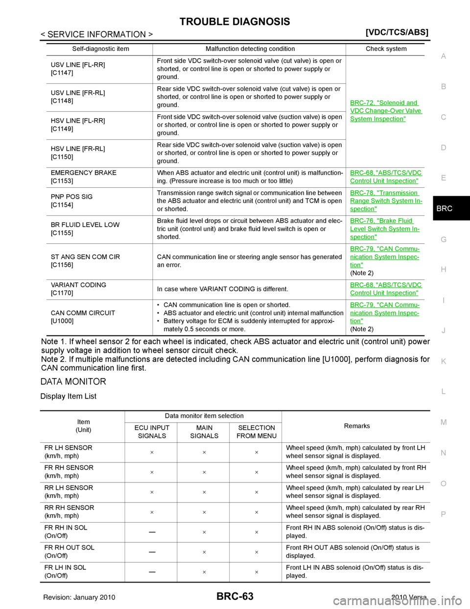
Note 1. If wheel sensor 2 for each wheel is indicated, check ABS actuator and electric unit (control unit) power
supply voltage in addition to wheel sensor circuit check.
Note 2. If multiple malfunctions are detected including CAN communication line [U1000], perform diagnosis for
CAN communication line first.
DATA MONITOR
Display Item List
USV LINE [FL-RR]
[C1147] Front side VDC switch-over solenoid valve (cut valve) is open or
shorted, or control line is open or shorted to power supply or
ground.
BRC-72, "
Solenoid and
VDC Change-Over Valve
System Inspection"
USV LINE [FR-RL]
[C1148]Rear side VDC switch-over solenoid valve (cut valve) is open or
shorted, or control line is open or shorted to power supply or
ground.
HSV LINE [FL-RR]
[C1149] Front side VDC switch-over solenoid valve (suction valve) is open
or shorted, or control line is open or shorted to power supply or
ground.
HSV LINE [FR-RL]
[C1150] Rear side VDC switch-over solenoid valve (suction valve) is open
or shorted, or control line is open or shorted to power supply or
ground.
EMERGENCY BRAKE
[C1153] When ABS actuator and el
ectric unit (control unit) is malfunction-
ing. (Pressure increase is too much or too little) BRC-68, "
ABS/TCS/VDC
Control Unit Inspection"
PNP POS SIG
[C1154]Transmission range switch signal or communication line between
the ABS actuator and electric unit (control unit) and TCM is open
or shorted. BRC-78, "Transmission
Range Switch System In-
spection"
BR FLUID LEVEL LOW
[C1155]
Brake fluid level drops or circuit between ABS actuator and elec-
tric unit (control unit) and brake fluid level switch is open or
shorted. BRC-76, "Brake Fluid
Level Switch System In-
spection"
ST ANG SEN COM CIR
[C1156]
CAN communication line or steering angle sensor has generated
an error. BRC-79, "
CAN Commu-
nication System Inspec-
tion"
(Note 2)
VARIANT CODING
[C1170] In case where VARIANT CODING is different. BRC-68, "
ABS/TCS/VDC
Control Unit Inspection"
CAN COMM CIRCUIT
[U1000]• CAN communication line is open or shorted.
• ABS actuator and electric unit (control unit) internal malfunction
• Battery voltage for ECM is suddenly interrupted for approxi-
mately 0.5 seconds or more. BRC-79, "
CAN Commu-
nication System Inspec-
tion"
(Note 2)
Self-diagnostic item
Malfunction detecting condition Check system
Item
(Unit) Data monitor item selection
Remarks
ECU INPUT
SIGNALS MAIN
SIGNALS SELECTION
FROM MENU
FR LH SENSOR
(km/h, mph) ××× Wheel speed (km/h, mph) calculated by front LH
wheel sensor signal is displayed.
FR RH SENSOR
(km/h, mph) ××× Wheel speed (km/h, mph) calculated by front RH
wheel sensor signal is displayed.
RR LH SENSOR
(km/h, mph) ×××
Wheel speed (km/h, mph) calculated by rear LH
wheel sensor signal is displayed.
RR RH SENSOR
(km/h, mph) ××× Wheel speed (km/h, mph) calculated by rear RH
wheel sensor signal is displayed.
FR RH IN SOL
(On/Off) —
×× Front RH IN ABS solenoid (On/Off) status is dis-
played.
FR RH OUT SOL
(On/Off) —
×× Front RH OUT ABS solenoid (On/Off) status is
displayed.
FR LH IN SOL
(On/Off) —
×× Front LH IN ABS solenoid (On/Off) status is dis-
played.
Revision: January 20102010 Versa
Page 959 of 3745
TROUBLE DIAGNOSIS FOR SELF-DIAGNOSTIC ITEMS
BRC-69
< SERVICE INFORMATION > [VDC/TCS/ABS]
C
D
E
G H
I
J
K L
M A
B
BRC
N
O P
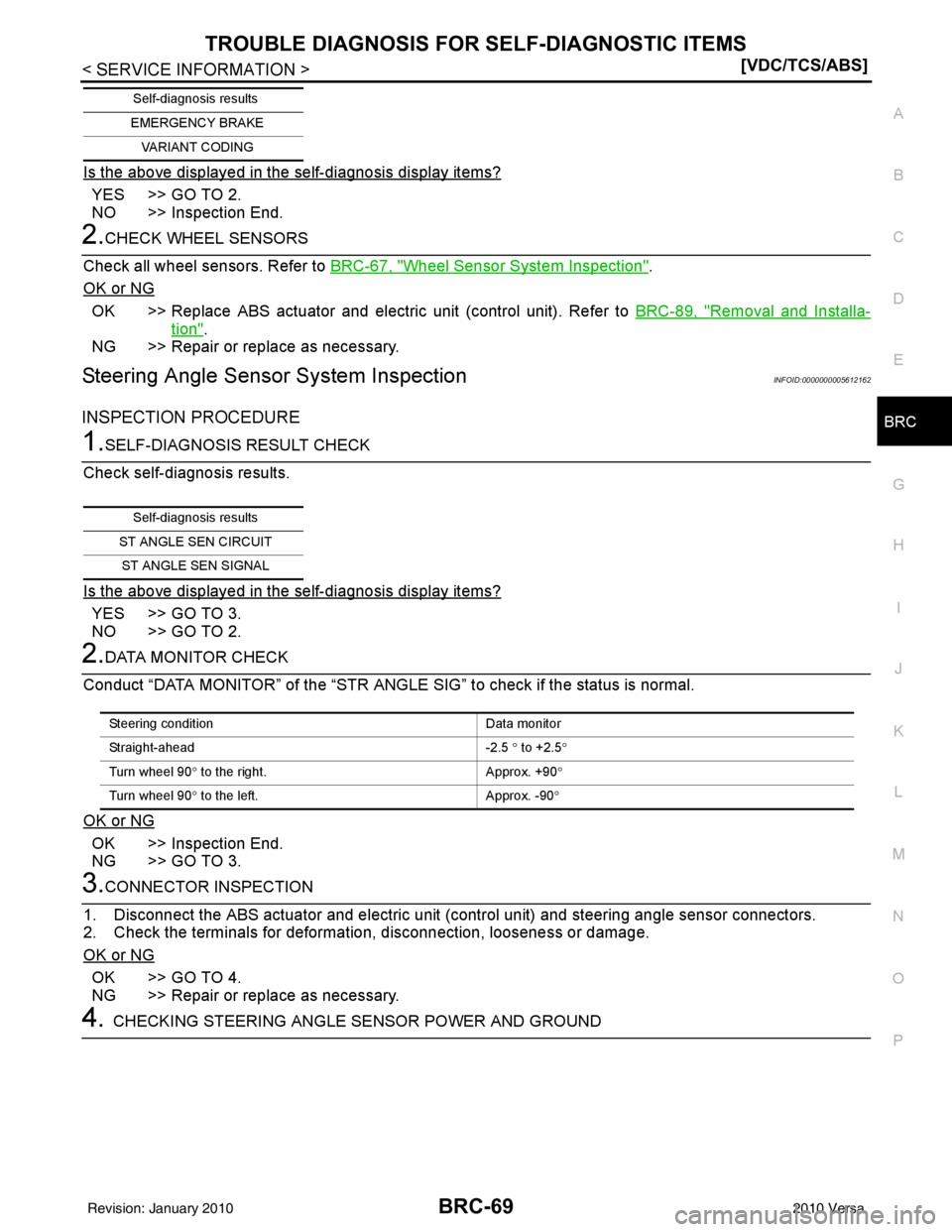
Is the above displayed in the self-diagnosis display items?
YES >> GO TO 2.
NO >> Inspection End.
2.CHECK WHEEL SENSORS
Check all wheel sensors. Refer to BRC-67, "
Wheel Sensor System Inspection".
OK or NG
OK >> Replace ABS actuator and electric unit (control unit). Refer to BRC-89, "Removal and Installa-
tion".
NG >> Repair or replace as necessary.
Steering Angle Sensor System InspectionINFOID:0000000005612162
INSPECTION PROCEDURE
1.SELF-DIAGNOSIS RESULT CHECK
Check self-diagnosis results.
Is the above displayed in the self-diagnosis display items?
YES >> GO TO 3.
NO >> GO TO 2.
2.DATA MONITOR CHECK
Conduct “DATA MONITOR” of t he “STR ANGLE SIG” to check if the status is normal.
OK or NG
OK >> Inspection End.
NG >> GO TO 3.
3.CONNECTOR INSPECTION
1. Disconnect the ABS actuator and el ectric unit (control unit) and steering angle sensor connectors.
2. Check the terminals for deformation, disconnection, looseness or damage.
OK or NG
OK >> GO TO 4.
NG >> Repair or replace as necessary.
4.CHECKING STEERING ANGLE SENSOR POWER AND GROUND
EMERGENCY BRAKE
VARIANT CODING
Self-diagnosis results
Self-diagnosis results
ST ANGLE SEN CIRCUIT ST ANGLE SEN SIGNAL
Steering condition Data monitor
Straight-ahead -2.5 ° to +2.5 °
Turn wheel 90 ° to the right. Approx. +90°
Turn wheel 90 ° to the left. Approx. -90°
Revision: January 20102010 Versa
Page 975 of 3745
ON-VEHICLE SERVICEBRC-85
< SERVICE INFORMATION > [VDC/TCS/ABS]
C
D
E
G H
I
J
K L
M A
B
BRC
N
O P
ON-VEHICLE SERVICE
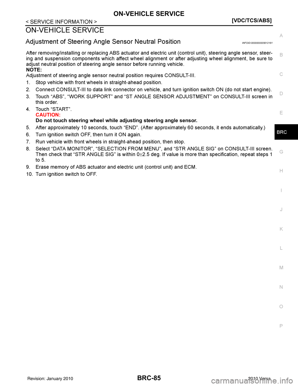
Adjustment of Steering Angle Sensor Neutral PositionINFOID:0000000005612181
After removing/installing or replacing ABS actuator and electric unit (control unit), steering angle sensor, steer-
ing and suspension components which affect wheel alignment or after adjusting wheel alignment, be sure to
adjust neutral position of steering angle sensor before running vehicle.
NOTE:
Adjustment of steering angle sensor neutral position requires CONSULT-III.
1. Stop vehicle with front wheels in straight-ahead position.
2. Connect CONSULT-III to data link connector on vehicle, and turn ignition switch ON (do not start engine).
3. Touch “ABS”, “WORK SUPPORT” and “ST ANGLE SENSOR ADJUSTMENT” on CONSULT-III screen in
this order.
4. Touch “START”. CAUTION:
Do not touch steering wheel whil e adjusting steering angle sensor.
5. After approximately 10 seconds, touch “END”. (After approximately 60 seconds, it ends automatically.)
6. Turn ignition switch OFF, then turn it ON again.
7. Run vehicle with front wheels in straight-ahead position, then stop.
8. Select “DATA MONITOR”, “SELECTION FROM MENU”, and “STR ANGLE SIG” on CONSULT-III screen.
Then check that “STR ANGLE SIG” is within 0 ±2.5 deg. If value is more than specification, repeat steps 1
to 5.
9. Erase memory of ABS actuator and electric unit (control unit) and ECM.
10. Turn ignition switch to OFF.
Revision: January 20102010 Versa