air bag NISSAN TIIDA 2010 Service Manual PDF
[x] Cancel search | Manufacturer: NISSAN, Model Year: 2010, Model line: TIIDA, Model: NISSAN TIIDA 2010Pages: 3745, PDF Size: 73.67 MB
Page 2831 of 3745
LAN-22
< SERVICE INFORMATION >[CAN]
HOW TO USE THIS SECTION
SERVICE INFORMATION
HOW TO USE THIS SECTION
CautionINFOID:0000000005395128
• This section describes information pecul
iar to a vehicle and inspection procedures.
• For trouble diagnosis procedure, refer to LAN-17, "
Trouble Diagnosis Procedure".
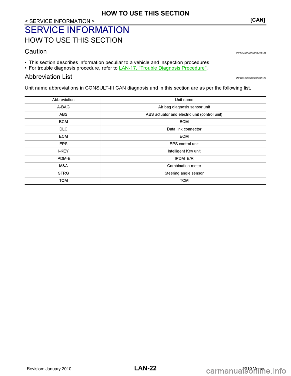
Abbreviation ListINFOID:0000000005395129
Unit name abbreviations in CONSULT-III CAN diagnosis and in this section are as per the following list.
Abbreviation Unit name
A-BAG Air bag diagnosis sensor unit
ABS ABS actuator and electric unit (control unit)
BCM BCM
DLC Data link connector
ECM ECM
EPS EPS control unit
I-KEY Intelligent Key unit
IPDM-E IPDM E/R
M&A Combination meter
STRG Steering angle sensor
TCM TCM
Revision: January 20102010 Versa
Page 2832 of 3745
PRECAUTIONSLAN-23
< SERVICE INFORMATION > [CAN]
C
D
E
F
G H
I
J
L
M A
B
LAN
N
O P
PRECAUTIONS
Precaution for Supplemental Restraint System (SRS) "AIR BAG" and "SEAT BELT
PRE-TENSIONER"
INFOID:0000000006007865
The Supplemental Restraint System such as “AIR BAG” and “SEAT BELT PRE-TENSIONER”, used along
with a front seat belt, helps to reduce the risk or severi ty of injury to the driver and front passenger for certain
types of collision. This system includes seat belt switch inputs and dual stage front air bag modules. The SRS
system uses the seat belt switches to determine the front air bag deployment, and may only deploy one front
air bag, depending on the severity of a collision and w hether the front occupants are belted or unbelted.
Information necessary to service the system safely is included in the SRS and SB section of this Service Man-
ual.
WARNING:
• To avoid rendering the SRS inoper ative, which could increase the risk of personal injury or death in
the event of a collision which would result in air bag inflation, all maintenance must be performed by
an authorized NISSAN/INFINITI dealer.
• Improper maintenance, including in correct removal and installation of the SRS can lead to personal
injury caused by unintentional act ivation of the system. For removal of Spiral Cable and Air Bag
Module, see the SRS section.
• Do not use electrical test equipm ent on any circuit related to the SRS unless instructed to in this
Service Manual. SRS wiring harnesses can be identi fied by yellow and/or orange harnesses or har-
ness connectors.
PRECAUTIONS WHEN USING POWER TOOLS (AIR OR ELECTRIC) AND HAMMERS
WARNING:
• When working near the Airbag Diagnosis Sensor Un it or other Airbag System sensors with the Igni-
tion ON or engine running, DO NOT use air or el ectric power tools or strike near the sensor(s) with a
hammer. Heavy vibration could activate the sensor( s) and deploy the air bag(s), possibly causing
serious injury.
• When using air or electric power tools or hammers, always switch the Ignition OFF, disconnect the battery, and wait at least 3 minutes before performing any service.
Precautions for Trouble DiagnosisINFOID:0000000005395131
CAUTION:
• Never apply 7.0 V or more to the measurement terminal.
• Use a tester with open terminal voltage of 7.0 V or less.
• Turn the ignition switch OFF and disconnect th e battery cable from the negative terminal when
checking the harness.
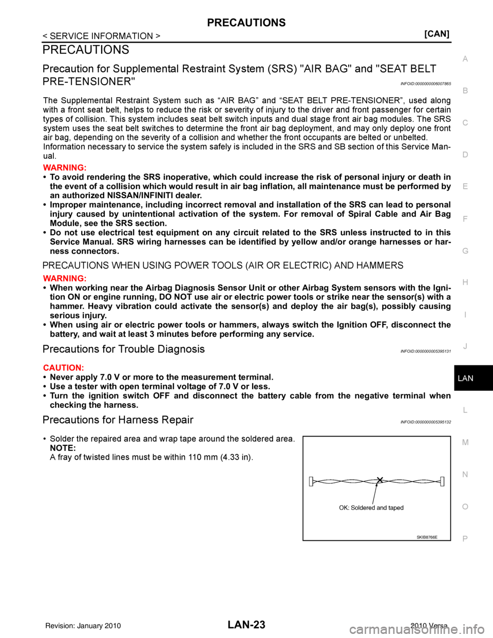
Precautions for Harness RepairINFOID:0000000005395132
• Solder the repaired area and wrap tape around the soldered area. NOTE:
A fray of twisted lines must be within 110 mm (4.33 in).
SKIB8766E
Revision: January 20102010 Versa
Page 2837 of 3745
LAN-28
< SERVICE INFORMATION >[CAN]
CAN COMMUNICATION SYSTEM
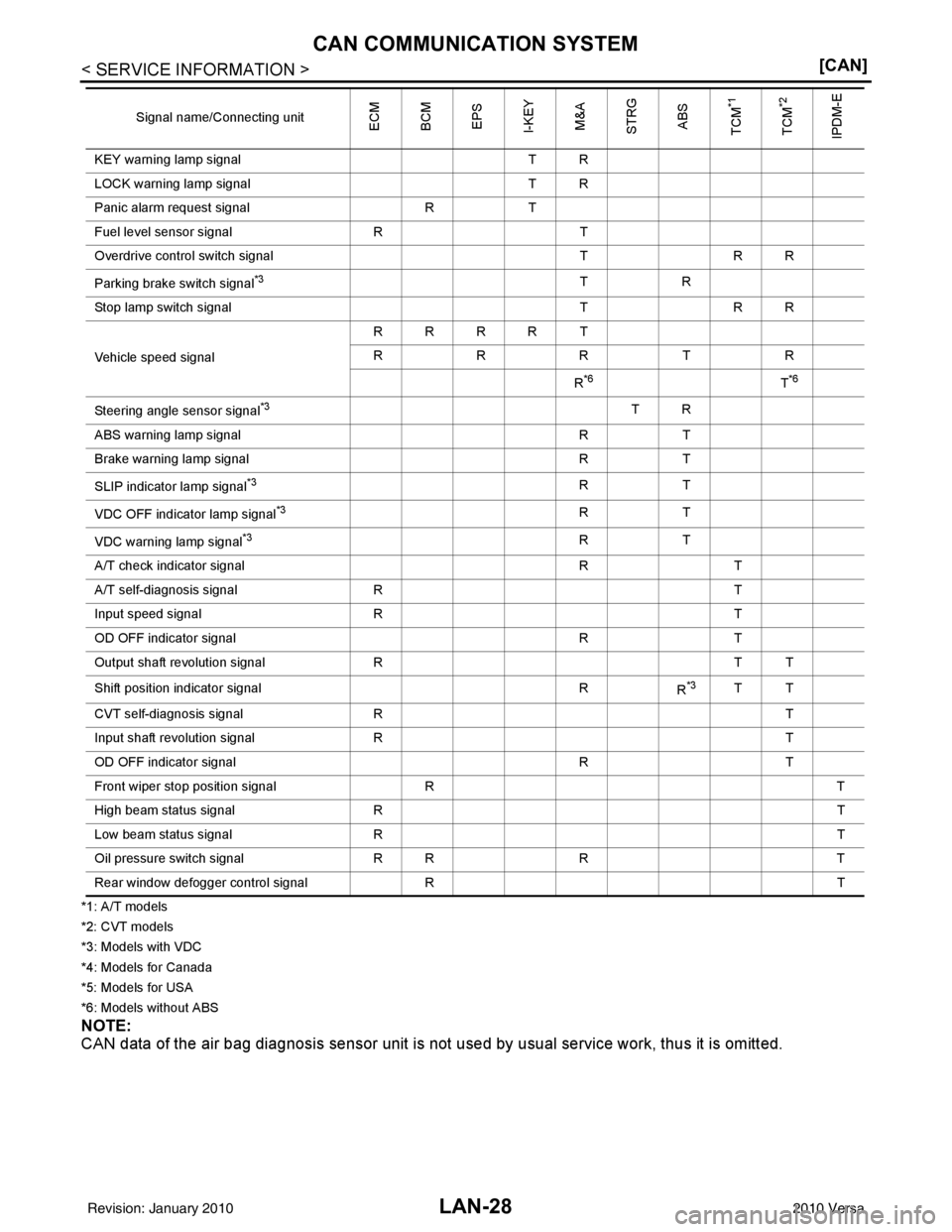
*1: A/T models
*2: CVT models
*3: Models with VDC
*4: Models for Canada
*5: Models for USA
*6: Models without ABS
NOTE:
CAN data of the air bag diagnosis sensor unit is not used by usual service work, thus it is omitted.
KEY warning lamp signal
T R
LOCK warning lamp signal T R
Panic alarm request signal RT
Fuel level sensor signal RT
Overdrive control switch signal TR R
Parking brake switch signal
*3TR
Stop lamp switch signal T R R
Vehicle speed signal RRRR T
RRR T R
R
*6T*6
Steering angle sensor signal*3TR
ABS warning lamp signal RT
Brake warning lamp signal RT
SLIP indicator lamp signal
*3RT
VDC OFF indicator lamp signal
*3RT
VDC warning lamp signal
*3RT
A/T check indicator signal RT
A/T self-diagnosis signal R T
Input speed signal R T
OD OFF indicator signal RT
Output shaft revolution signal R T T
Shift position indicator signal R
R
*3TT
CVT self-diagnosis signal R T
Input shaft revolution signal R T
OD OFF indicator signal RT
Front wiper stop position signal R T
High beam status signal R T
Low beam status signal R T
Oil pressure switch signal R RR T
Rear window defogger control signal R T
Signal name/Connecting unit
ECM
BCM
EPS
I-KEY M&A
STRG ABS
TCM
*1
TCM
*2
IPDM-E
Revision: January 20102010 Versa
Page 2838 of 3745
CAN COMMUNICATION SYSTEMLAN-29
< SERVICE INFORMATION > [CAN]
C
D
E
F
G H
I
J
L
M A
B
LAN
N
O P
CAN COMMUNICATION SYSTEM
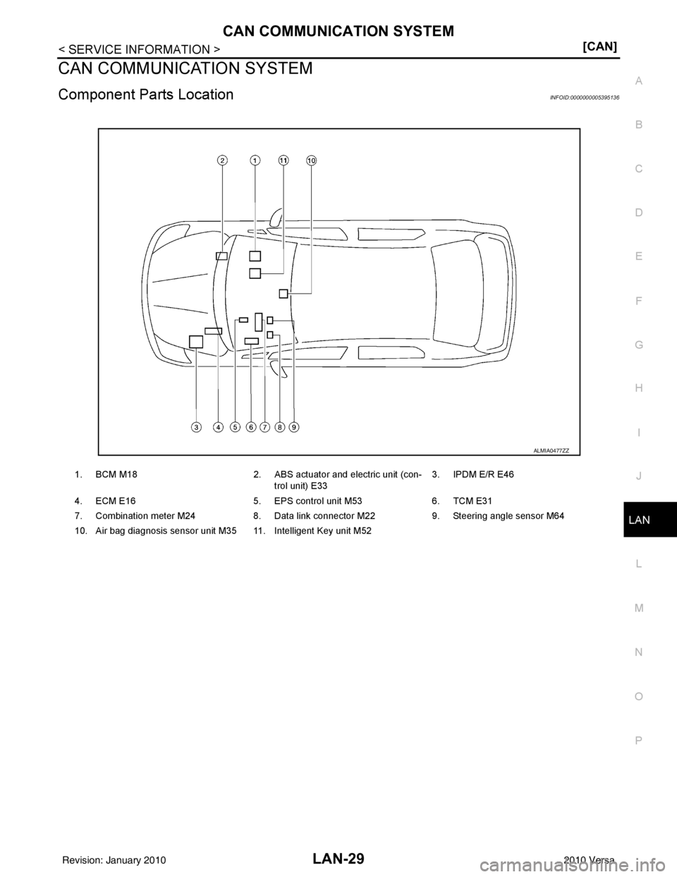
Component Parts LocationINFOID:0000000005395136
1. BCM M18 2. ABS actuator and electric unit (con-
trol unit) E33 3. IPDM E/R E46
4. ECM E16 5. EPS control unit M536. TCM E31
7. Combination meter M24 8. Data link connector M22 9. Steering angle sensor M64
10. Air bag diagnosis sensor unit M35 11. Intelligent Key unit M52
ALMIA0477ZZ
Revision: January 20102010 Versa
Page 2996 of 3745
LT-1
ELECTRICAL
C
DE
F
G H
I
J
L
M
SECTION LT
A
B
LT
N
O P
CONTENTS
LIGHTING SYSTEM
SERVICE INFORMATION .. ..........................3
PRECAUTIONS .............................................. .....3
Precaution for Supplemental Restraint System
(SRS) "AIR BAG" and "SEAT BELT PRE-TEN-
SIONER" ............................................................. ......
3
Precaution Necessary for Steering Wheel Rota-
tion After Battery Disconnect ............................... ......
3
PREPARATION ...................................................5
Special Service Tool ........................................... ......5
HEADLAMP (FOR USA) .....................................6
Component Parts and Harness Connector Loca-
tion ...................................................................... ......
6
System Description ...................................................6
CAN COMMUNICATION SYSTEM DESCRIP-
TION .................................................................... ......
7
Schematic .................................................................8
Wiring Diagram .........................................................9
Terminal and Reference Value for BCM .................12
Terminal and Reference Value for IPDM E/R .........12
How to Perform Trouble Diagnosis .........................13
Preliminary Check ...................................................13
CONSULT-III Function (BCM) .................................13
CONSULT-III Function (IPDM E/R) .........................14
Headlamp High Beam Does Not Illuminate (Both
Sides) .................................................................. ....
16
Headlamp High Beam Does Not Illuminate (One
Side) .................................................................... ....
18
High Beam Indicator Lamp Does Not Illuminate .....19
Headlamp Low Beam Does Not Illuminate (Both
Sides) .................................................................. ....
20
Headlamp Low Beam Does Not Illuminate (One
Side) .................................................................... ....
22
Headlamps Do Not Turn OFF .................................23
Aiming Adjustment ..................................................24
Bulb Replacement ...................................................25
Removal and Installation .........................................26
Disassembly and Assembly ................................ ....26
HEADLAMP (FOR CANADA) - DAYTIME
LIGHT SYSTEM - ..............................................
28
Component Parts and Harness Connector Loca-
tion ....................................................................... ....
28
System Description ..................................................28
CAN Communication System Description ...............30
Schematic ................................................................31
Wiring Diagram - DTRL - .........................................32
Terminal and Reference Value for BCM ..................35
Terminal and Reference Value for IPDM E/R ...... ....35
How to Perform Trouble Diagnosis ..........................36
Preliminary Check ...................................................36
CONSULT-III Function (BCM) .................................36
CONSULT-III Function (IPDM E/R) ..................... ....36
Daytime Light Control Does Not Operate Properly
(High Beam Headlamps Operate Properly) .............
36
Aiming Adjustment ...................................................38
Bulb Replacement ...................................................39
Removal and Installation .........................................40
Disassembly and Assembly .....................................40
FRONT FOG LAMP ..........................................42
Component Parts and Harness Connector Loca-
tion ...........................................................................
42
System Description ..................................................42
CAN Communication System Description ...............43
Wiring Diagram - F/FOG - .......................................44
Terminal and Reference Value for BCM ..................45
Terminal and Reference Value for IPDM E/R ...... ....45
How to Proceed with Trouble Diagnosis ..................46
Preliminary Check ............................................... ....46
CONSULT-III Function (BCM) .................................46
CONSULT-III Function (IPDM E/R) ..................... ....46
Front Fog lamps Do Not Illuminate (Both Sides) .....46
Front Fog Lamp Does Not Illuminate (One Side) ....48
Aiming Adjustment ...................................................49
Bulb Replacement ...................................................50
Removal and Installation .........................................50
TURN SIGNAL AND HAZARD WARNING
LAMPS ..............................................................
51
Revision: January 20102010 Versa
Page 2998 of 3745
PRECAUTIONSLT-3
< SERVICE INFORMATION >
C
DE
F
G H
I
J
L
M A
B
LT
N
O P
SERVICE INFORMATION
PRECAUTIONS
Precaution for Supplemental Restraint System (SRS) "AIR BAG" and "SEAT BELT
PRE-TENSIONER"
INFOID:0000000005716032
The Supplemental Restraint System such as “AIR BAG” and “SEAT BELT PRE-TENSIONER”, used along
with a front seat belt, helps to reduce the risk or severi ty of injury to the driver and front passenger for certain
types of collision. This system includes seat belt switch inputs and dual stage front air bag modules. The SRS
system uses the seat belt switches to determine the front air bag deployment, and may only deploy one front
air bag, depending on the severity of a collision and w hether the front occupants are belted or unbelted.
Information necessary to service the system safely is included in the SRS and SB section of this Service Man-
ual.
WARNING:
• To avoid rendering the SRS inoper ative, which could increase the risk of personal injury or death in
the event of a collision which would result in air bag inflation, all maintenance must be performed by
an authorized NISSAN/INFINITI dealer.
• Improper maintenance, including in correct removal and installation of the SRS can lead to personal
injury caused by unintentional act ivation of the system. For removal of Spiral Cable and Air Bag
Module, see the SRS section.
• Do not use electrical test equipm ent on any circuit related to the SRS unless instructed to in this
Service Manual. SRS wiring harnesses can be identi fied by yellow and/or orange harnesses or har-
ness connectors.
PRECAUTIONS WHEN USING POWER TOOLS (AIR OR ELECTRIC) AND HAMMERS
WARNING:
• When working near the Airbag Diagnosis Sensor Un it or other Airbag System sensors with the Igni-
tion ON or engine running, DO NOT use air or el ectric power tools or strike near the sensor(s) with a
hammer. Heavy vibration could activate the sensor( s) and deploy the air bag(s), possibly causing
serious injury.
• When using air or electric power tools or hammers, always switch the Ignition OFF, disconnect the battery, and wait at least 3 minutes before performing any service.
Precaution Necessary for Steering Wheel Rotation After Battery Disconnect
INFOID:0000000005394874
NOTE:
• This Procedure is applied only to models with Intelligent Key system and NATS (NISSAN ANTI-THEFT SYS-
TEM).
• Remove and install all control units after disconnecti ng both battery cables with the ignition knob in the
″ LOCK ″ position.
• Always use CONSULT-III to perform self-diagnosis as a part of each function inspection after finishing work.
If DTC is detected, perform trouble diagnosis according to self-diagnostic results.
For models equipped with the Intelligent Key system and NATS , an electrically controlled steering lock mech-
anism is adopted on the key cylinder.
For this reason, if the battery is disconnected or if the battery is discharged, the steering wheel will lock and
steering wheel rotation will become impossible.
If steering wheel rotation is required when battery power is interrupted, follow the procedure below before
starting the repair operation.
OPERATION PROCEDURE
1. Connect both battery cables. NOTE:
Supply power using jumper cables if battery is discharged.
2. Use the Intelligent Key or mechanical key to turn the ignition switch to the ″ACC ″ position. At this time, the
steering lock will be released.
3. Disconnect both battery cables. The steering lock will remain released and the steering wheel can be
rotated.
4. Perform the necessary repair operation.
Revision: January 20102010 Versa
Page 3113 of 3745
LU-1
ENGINE
C
DE
F
G H
I
J
K L
M
SECTION LU
A
LU
N
O P
CONTENTS
ENGINE LUBRICATION SYSTEM
HR16DE
PRECAUTION ....... ........................................
2
PRECAUTIONS .............................................. .....2
Precaution for Supplemental Restraint System
(SRS) "AIR BAG" and "SEAT BELT PRE-TEN-
SIONER" ............................................................. ......
2
Precaution Necessary for Steering Wheel Rota-
tion After Battery Disconnect ............................... ......
2
Precaution for Liquid Gasket .....................................3
PREPARATION ............................................4
PREPARATION .............................................. .....4
Special Service Tool ........................................... ......4
Commercial Service Tool ..........................................4
FUNCTION DIAGNOSIS ...............................6
DESCRIPTION ............................................... .....6
Engine Lubrication System ................................. ......6
Engine Lubrication System Schematic ......................6
ON-VEHICLE MAINTENANCE .....................7
ENGINE OIL ................................................... .....7
Inspection ............................................................ ......7
Draining .....................................................................8
Refilling .....................................................................8
OIL FILTER .........................................................9
Removal and Installation ...........................................9
ON-VEHICLE REPAIR .... .............................10
OIL PUMP ....................................................... ....10
Removal and Installation .........................................10
SERVICE DATA AND SPECIFICATIONS
(SDS) ............... .......................................... ...
11
SERVICE DATA AND SPECIFICATIONS
(SDS) .................................................................
11
Engine Oil Capacity ............................................. ....11
Engine Oil Pressure .................................................11
MR18DE
SERVICE INFORMATION .. .........................
12
PRECAUTIONS .................................................12
Precaution for Supplemental Restraint System
(SRS) "AIR BAG" and "SEAT BELT PRE-TEN-
SIONER" ............................................................. ....
12
Precaution Necessary for Steering Wheel Rota-
tion After Battery Disconnect ...................................
12
Precaution for Liquid Gasket ...................................13
PREPARATION .................................................14
Special Service Tool ................................................14
Commercial Service Tool ........................................14
LUBRICATION SYSTEM ..................................16
Lubrication Circuit ....................................................16
ENGINE OIL ......................................................17
Inspection ................................................................17
Changing Engine Oil ................................................18
OIL FILTER .......................................................20
Removal and Installation .........................................20
OIL PUMP .........................................................21
Component ..............................................................21
Removal and Installation .........................................21
SERVICE DATA AND SPECIFICATIONS
(SDS) .................................................................
23
Standard and Limit ..................................................23
Revision: January 20102010 Versa
Page 3114 of 3745
LU-2
< PRECAUTION >[HR16DE]
PRECAUTIONS
PRECAUTION
PRECAUTIONS
Precaution for Supplemental Restraint Syst
em (SRS) "AIR BAG" and "SEAT BELT
PRE-TENSIONER"
INFOID:0000000005713914
The Supplemental Restraint System such as “A IR BAG” and “SEAT BELT PRE-TENSIONER”, used along
with a front seat belt, helps to reduce the risk or severity of injury to the driver and front passenger for certain
types of collision. This system includes seat belt switch inputs and dual stage front air bag modules. The SRS
system uses the seat belt switches to determine the front air bag deployment, and may only deploy one front
air bag, depending on the severity of a collision and w hether the front occupants are belted or unbelted.
Information necessary to service the system safely is included in the SRS and SB section of this Service Man-
ual.
WARNING:
• To avoid rendering the SRS inopera tive, which could increase the risk of personal injury or death in
the event of a collision which would result in air bag inflation, all maintenance must be performed by
an authorized NISSAN/INFINITI dealer.
• Improper maintenance, including incorrect removal and installation of the SRS can lead to personal
injury caused by unintent ional activation of the system. For re moval of Spiral Cable and Air Bag
Module, see the SRS section.
• Do not use electrical test equipmen t on any circuit related to the SRS unless instructed to in this
Service Manual. SRS wiring harn esses can be identified by yellow and/or orange harnesses or har-
ness connectors.
PRECAUTIONS WHEN USING POWER TOOLS (AIR OR ELECTRIC) AND HAMMERS
WARNING:
• When working near the Airbag Diagnosis Sensor Unit or other Airbag System sensors with the Igni-
tion ON or engine running, DO NOT use air or electri c power tools or strike near the sensor(s) with a
hammer. Heavy vibration could activate the sensor( s) and deploy the air bag(s), possibly causing
serious injury.
• When using air or electric power tools or hammers , always switch the Ignition OFF, disconnect the
battery, and wait at least 3 minu tes before performing any service.
Precaution Necessary for Steering W heel Rotation After Battery Disconnect
INFOID:0000000005398151
NOTE:
• This Procedure is applied only to models with Intelligent Key system and NATS (NISSAN ANTI-THEFT SYS-
TEM).
• Remove and install all control units after disconnecting both battery cables with the ignition knob in the
″LOCK ″ position.
• Always use CONSULT-III to perform self-diagnosis as a part of each function inspection after finishing work.
If DTC is detected, perform trouble diagnosis according to self-diagnostic results.
For models equipped with the Intelligent Key system and NATS, an electrically controlled steering lock mech-
anism is adopted on the key cylinder.
For this reason, if the battery is disconnected or if the battery is discharged, the steering wheel will lock and
steering wheel rotation will become impossible.
If steering wheel rotation is required when battery pow er is interrupted, follow the procedure below before
starting the repair operation.
OPERATION PROCEDURE
1. Connect both battery cables. NOTE:
Supply power using jumper cables if battery is discharged.
2. Use the Intelligent Key or mechanical key to turn the ignition switch to the ″ACC ″ position. At this time, the
steering lock will be released.
3. Disconnect both battery cables. The steering lock will remain released and the steering wheel can be rotated.
4. Perform the necessary repair operation.
Revision: January 20102010 Versa
Page 3124 of 3745
LU-12
< SERVICE INFORMATION >[MR18DE]
PRECAUTIONS
SERVICE INFORMATION
PRECAUTIONS
Precaution for Supplemental Restraint Syst
em (SRS) "AIR BAG" and "SEAT BELT
PRE-TENSIONER"
INFOID:0000000005713915
The Supplemental Restraint System such as “A IR BAG” and “SEAT BELT PRE-TENSIONER”, used along
with a front seat belt, helps to reduce the risk or severity of injury to the driver and front passenger for certain
types of collision. This system includes seat belt switch inputs and dual stage front air bag modules. The SRS
system uses the seat belt switches to determine the front air bag deployment, and may only deploy one front
air bag, depending on the severity of a collision and w hether the front occupants are belted or unbelted.
Information necessary to service the system safely is included in the SRS and SB section of this Service Man-
ual.
WARNING:
• To avoid rendering the SRS inopera tive, which could increase the risk of personal injury or death in
the event of a collision which would result in air bag inflation, all maintenance must be performed by
an authorized NISSAN/INFINITI dealer.
• Improper maintenance, including incorrect removal and installation of the SRS can lead to personal
injury caused by unintent ional activation of the system. For re moval of Spiral Cable and Air Bag
Module, see the SRS section.
• Do not use electrical test equipmen t on any circuit related to the SRS unless instructed to in this
Service Manual. SRS wiring harn esses can be identified by yellow and/or orange harnesses or har-
ness connectors.
PRECAUTIONS WHEN USING POWER TOOLS (AIR OR ELECTRIC) AND HAMMERS
WARNING:
• When working near the Airbag Diagnosis Sensor Unit or other Airbag System sensors with the Igni-
tion ON or engine running, DO NOT use air or electri c power tools or strike near the sensor(s) with a
hammer. Heavy vibration could activate the sensor( s) and deploy the air bag(s), possibly causing
serious injury.
• When using air or electric power tools or hammers , always switch the Ignition OFF, disconnect the
battery, and wait at least 3 minu tes before performing any service.
Precaution Necessary for Steering W heel Rotation After Battery Disconnect
INFOID:0000000005398164
NOTE:
• This Procedure is applied only to models with Intelligent Key system and NATS (NISSAN ANTI-THEFT SYS-
TEM).
• Remove and install all control units after disconnecting both battery cables with the ignition knob in the
″LOCK ″ position.
• Always use CONSULT-III to perform self-diagnosis as a part of each function inspection after finishing work.
If DTC is detected, perform trouble diagnosis according to self-diagnostic results.
For models equipped with the Intelligent Key system and NATS, an electrically controlled steering lock mech-
anism is adopted on the key cylinder.
For this reason, if the battery is disconnected or if the battery is discharged, the steering wheel will lock and
steering wheel rotation will become impossible.
If steering wheel rotation is required when battery pow er is interrupted, follow the procedure below before
starting the repair operation.
OPERATION PROCEDURE
1. Connect both battery cables. NOTE:
Supply power using jumper cables if battery is discharged.
2. Use the Intelligent Key or mechanical key to turn the ignition switch to the ″ACC ″ position. At this time, the
steering lock will be released.
3. Disconnect both battery cables. The steering lock will remain released and the steering wheel can be rotated.
4. Perform the necessary repair operation.
Revision: January 20102010 Versa
Page 3136 of 3745
MA-1
MAINTENANCE
C
DE
F
G H
I
J
K
M
SECTION MA
A
B
MA
N
O P
CONTENTS
MAINTENANCE
SERVICE INFORMATION .. ..........................3
PRECAUTIONS .............................................. .....3
Precaution for Supplemental Restraint System
(SRS) "AIR BAG" and "SEAT BELT PRE-TEN-
SIONER" ............................................................. ......
3
Precaution Necessary for Steering Wheel Rota-
tion After Battery Disconnect ............................... ......
3
PREPARATION ...................................................5
Special Service Tool ........................................... ......5
Commercial Service Tool ..........................................6
GENERAL MAINTENANCE ........................... .....7
Explanation of General Maintenance .................. ......7
General Maintenance ................................................7
PERIODIC MAINTENANCE ................................9
Introduction of Periodic Maintenance .................. ......9
Schedule 1 ................................................................9
Schedule 2 ..............................................................11
RECOMMENDED FLUIDS AND LUBRI-
CANTS ................................................................
14
Fluids and Lubricants .......................................... ....14
SAE Viscosity Number ............................................14
Anti-freeze Coolant Mixture Ratio ...........................15
ENGINE MAINTENANCE (HR16DE) .................16
DRIVE BELT .......................................................... ....16
DRIVE BELT : Checking .........................................16
DRIVE BELT : Tension Adjustment ........................16
ENGINE COOLANT ............................................... ....17
ENGINE COOLANT : Inspection .............................17
ENGINE COOLANT : Changing Engine Coolant ....17
FUEL LINES .......................................................... ....19
FUEL LINES : Checking Fuel Line ..........................19
AIR CLEANER FILTER ......................................... ....19
AIR CLEANER FILTER : Removal and Installation
....
20
ENGINE OIL ........................................................... ....20
ENGINE OIL : Inspection .........................................20
ENGINE OIL : Draining ............................................22
ENGINE OIL : Refilling ............................................22
OIL FILTER ............................................................ ....23
OIL FILTER : Removal and Installation ...................23
SPARK PLUG (HR16DE) ...................................... ....23
SPARK PLUG (HR16DE) : Exploded View .............24
SPARK PLUG (HR16DE) : Removal and Installa-
tion ....................................................................... ....
24
EVAP VAPOR LINES ............................................ ....25
EVAP VAPOR LINES : Checking EVAP Vapor
Line ..........................................................................
25
ENGINE MAINTENANCE (MR18DE) ...............26
DRIVE BELT .......................................................... ....26
DRIVE BELT : Component ......................................26
DRIVE BELT : Checking Drive Belts .......................26
DRIVE BELT : Tension Adjustment .........................26
ENGINE COOLANT ............................................... ....26
ENGINE COOLANT : Inspection .............................26
ENGINE COOLANT : Changing Engine Coolant ....27
FUEL LINES ........................................................... ....29
FUEL LINES : Checking Fuel Line ..........................29
AIR CLEANER FILTER ......................................... ....29
AIR CLEANER FILTER : Component ......................29
AIR CLEANER FILTER : Changing Air Cleaner
Filter .........................................................................
30
ENGINE OIL ........................................................... ....30
ENGINE OIL : Inspection .........................................30
ENGINE OIL : Changing Engine Oil ........................32
OIL FILTER ............................................................ ....33
Revision: January 20102010 Versa