weight NISSAN TIIDA 2010 Service Repair Manual
[x] Cancel search | Manufacturer: NISSAN, Model Year: 2010, Model line: TIIDA, Model: NISSAN TIIDA 2010Pages: 3745, PDF Size: 73.67 MB
Page 26 of 3745
PRECAUTIONSAT-9
< SERVICE INFORMATION >
DE
F
G H
I
J
K L
M A
B
AT
N
O P
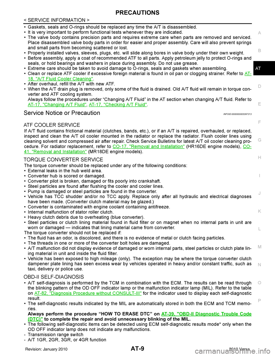
• Gaskets, seals and O-rings should be replaced any time the A/T is disassembled.
• It is very important to perform func tional tests whenever they are indicated.
• The valve body contains precision parts and requires extreme care when parts are removed and serviced.
Place disassembled valve body parts in order for easier and proper assembly. Care will also prevent springs
and small parts from becoming scattered or lost.
• Properly installed valves, sleeves, plugs, etc. will slide along bores in valve body under their own weight.
• Before assembly, apply a coat of recommended ATF to all parts. Apply petroleum jelly to protect O-rings and seals, or hold bearings and washers in pl ace during assembly. Do not use grease.
• Extreme care should be taken to avoid damage to O-rings, seals and gaskets when assembling.
• Clean or replace ATF cooler if excessive foreign material is found in oil pan or clogging strainer. Refer to AT-
18, "A/T Fluid Cooler Cleaning".
• After overhaul, refill the A/T with new ATF.
• When the A/T drain plug is removed, only some of the fluid is drained. Old A/T fluid will remain in torque con- verter and ATF cooling system.
Always follow the procedures under “Changing A/T Fluid” in the AT section when changing A/T fluid. Refer to
AT-17, "
Changing A/T Fluid", AT-17, "Checking A/T Fluid".
Service Notice or PrecautionINFOID:0000000005397213
ATF COOLER SERVICE
If A/T fluid contains frictional material (clutches, bands, etc.), or if an A/T is repaired, overhauled, or replaced,
inspect and clean the A/T oil cooler mounted in the radiator or replace the radiator. Flush cooler lines using
cleaning solvent and compressed air after repair. Check Service Bulletins for latest A/T oil cooler cleaning pro-
cedure. For radiator replacement, refer to CO-17, "
Removal and Installation" (HR16DE engine models), CO-
41, "Removal and Installation" (MR18DE engine models).
TORQUE CONVERTER SERVICE
The torque converter should be replaced under any of the following conditions:
• External leaks in the hub weld area.
• Converter hub is scored or damaged.
• Converter pilot is broken, damaged or fits poorly into crankshaft.
• Steel particles are found after flushing the cooler and cooler lines.
• Pump is damaged or steel particles are found in the converter.
• Vehicle has TCC shudder and/or no TCC apply. Replace only after all hydraulic and electrical diagnoses
have been made. (Converter clutch material may be glazed.)
• Converter is contaminated with engi ne coolant containing antifreeze.
• Internal malfunction of stator roller clutch.
• Heavy clutch debris due to overheating (blue converter).
• Steel particles or clutch lining material found in flui d filter or on magnet when no internal parts in unit are
worn or damaged — indicates that lining material came from converter.
The torque converter should not be replaced if:
• The fluid has an odor, is discolored, and there is no evidence of metal or clutch facing particles.
• The threads in one or more of the converter bolt holes are damaged.
• A/T malfunction did not display evidence of damaged or worn internal parts, steel particles or clutch plate lin-
ing material in unit and inside the fluid filter.
• Vehicle has been exposed to high mileage (only). The e xception may be where the torque converter clutch
dampener plate lining has seen excess wear by vehicles operated in heavy and/or constant traffic, such as
taxi, delivery or police use.
OBD-II SELF-DIAGNOSIS
• A/T self-diagnosis is performed by the TCM in combination with the ECM. The results can be read through the blinking pattern of the OD OFF indicator lamp or the malfunction indicator lamp (MIL). Refer to the table
on AT-82, "
Diagnosis Procedure without CONSULT-III" for the indicator used to display each self-diagnostic
result.
• The self-diagnostic results indicated by the MIL are automatically stored in both the ECM and TCM memo- ries.
Always perform the procedure “HOW TO ERASE DTC” on AT-39, "
OBD-II Diagnostic Trouble Code
(DTC)" to complete the repair and avoid unnecessary blinking of the MIL.
• The following self-diagnostic items can be detected us ing ECM self-diagnostic results mode* only when the
OD OFF indicator lamp does not indicate any malfunctions.
- Transmission range switch
- A/T 1GR, 2GR, 3GR, or 4GR function
Revision: January 20102010 Versa
Page 128 of 3745
P0731 1GR INCORRECT RATIOAT-111
< SERVICE INFORMATION >
DE
F
G H
I
J
K L
M A
B
AT
N
O P
1. Remove control valve assembly. Refer to AT-222, "Control Valve Assembly and Accumulators".
- Shift solenoid valve A
- Shift solenoid valve B
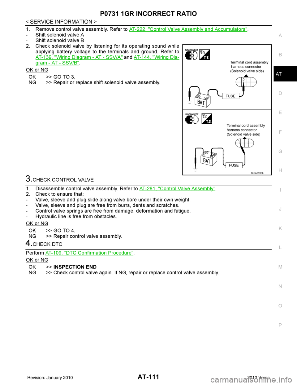
2. Check solenoid valve by listening for its operating sound while applying battery voltage to the terminals and ground. Refer to
AT-139, "
Wiring Diagram - AT - SSV/A" and AT-144, "Wiring Dia-
gram - AT - SSV/B".
OK or NG
OK >> GO TO 3.
NG >> Repair or replace shift solenoid valve assembly.
3.CHECK CONTROL VALVE
1. Disassemble control valve assembly. Refer to AT-281, "
Control Valve Assembly".
2. Check to ensure that:
- Valve, sleeve and plug slide along valve bore under their own weight.
- Valve, sleeve and plug are free from burrs, dents and scratches.
- Control valve springs are free from damage, deformation and fatigue.
- Hydraulic line is free from obstacles.
OK or NG
OK >> GO TO 4.
NG >> Repair control valve assembly.
4.CHECK DTC
Perform AT-109, "
DTC Confirmation Procedure".
OK or NG
OK >> INSPECTION END
NG >> Check control valve again. If NG, repa ir or replace control valve assembly.
SCIA3595E
Revision: January 20102010 Versa
Page 131 of 3745

AT-114
< SERVICE INFORMATION >
P0732 2GR INCORRECT RATIO
- Valve, sleeve and plug slide along valve bore under their own weight.
- Valve, sleeve and plug are free from burrs, dents and scratches.
- Control valve springs are free from damage, deformation and fatigue.
- Hydraulic line is free from obstacles.
OK or NG
OK >> GO TO 4.
NG >> Repair control valve assembly.
4.CHECK DTC
Perform AT-112, "
DTC Confirmation Procedure".
OK or NG
OK >> INSPECTION END
NG >> Check control valve again. If NG, repair or replace control valve assembly.
Revision: January 20102010 Versa
Page 134 of 3745
P0733 3GR INCORRECT RATIOAT-117
< SERVICE INFORMATION >
DE
F
G H
I
J
K L
M A
B
AT
N
O P
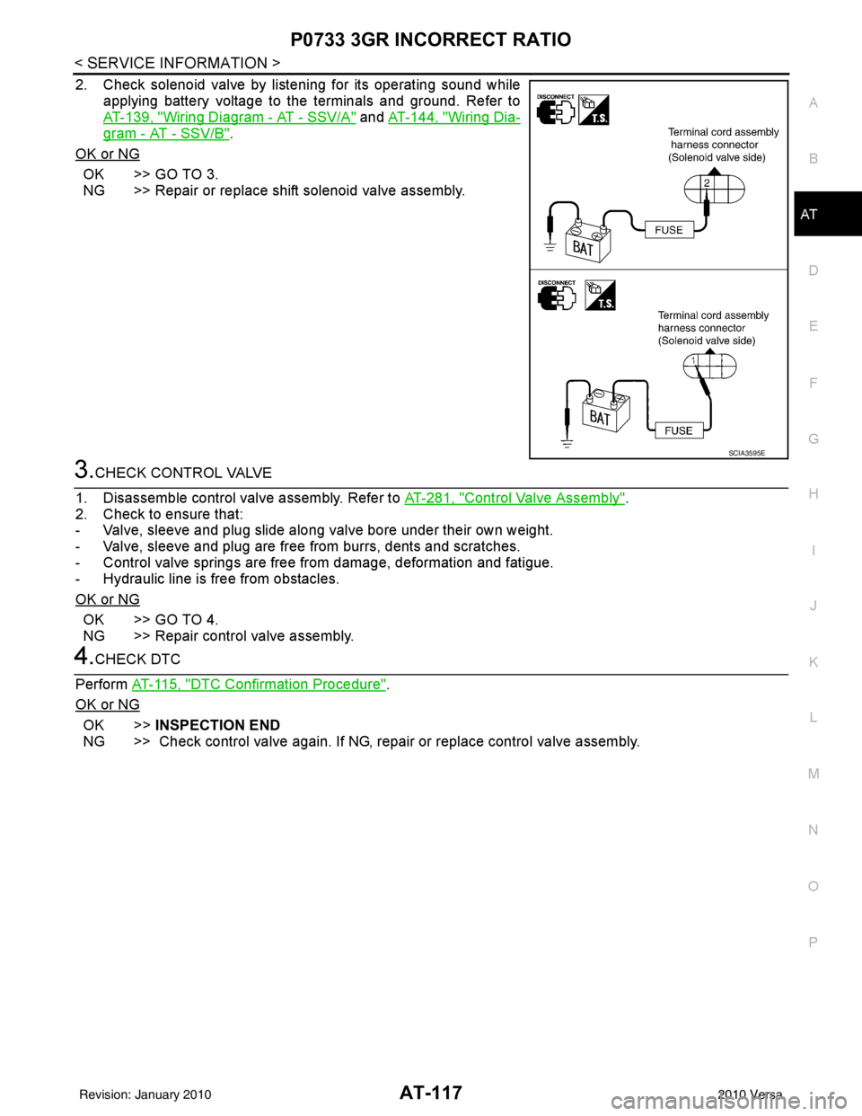
2. Check solenoid valve by listening for its operating sound while applying battery voltage to the terminals and ground. Refer to
AT-139, "
Wiring Diagram - AT - SSV/A" and AT-144, "Wiring Dia-
gram - AT - SSV/B".
OK or NG
OK >> GO TO 3.
NG >> Repair or replace shift solenoid valve assembly.
3.CHECK CONTROL VALVE
1. Disassemble control valve assembly. Refer to AT-281, "
Control Valve Assembly".
2. Check to ensure that:
- Valve, sleeve and plug slide along valve bore under their own weight.
- Valve, sleeve and plug are free from burrs, dents and scratches.
- Control valve springs are free from damage, deformation and fatigue.
- Hydraulic line is free from obstacles.
OK or NG
OK >> GO TO 4.
NG >> Repair control valve assembly.
4.CHECK DTC
Perform AT-115, "
DTC Confirmation Procedure".
OK or NG
OK >> INSPECTION END
NG >> Check control valve again. If NG, repair or replace control valve assembly.
SCIA3595E
Revision: January 20102010 Versa
Page 138 of 3745
P0734 4GR INCORRECT RATIOAT-121
< SERVICE INFORMATION >
DE
F
G H
I
J
K L
M A
B
AT
N
O P
- Valve, sleeve and plug slide along valve bore under their own weight.
- Valve, sleeve and plug are free from burrs, dents and scratches.
- Control valve springs are free from damage, deformation and fatigue.
- Hydraulic line is free from obstacles.
OK or NG
OK >> GO TO 6.
NG >> Repair control valve.
6.CHECK SHIFT-UP (D3 TO D4)
During AT-58, "
Cruise Test - Part 1".
Does A/T shift from D
3 to D4 at the specified speed?
YES >> GO TO 11.
NO >> Check control valve again. Repair or replace control valve assembly.
7.CHECK VALVE RESISTANCE
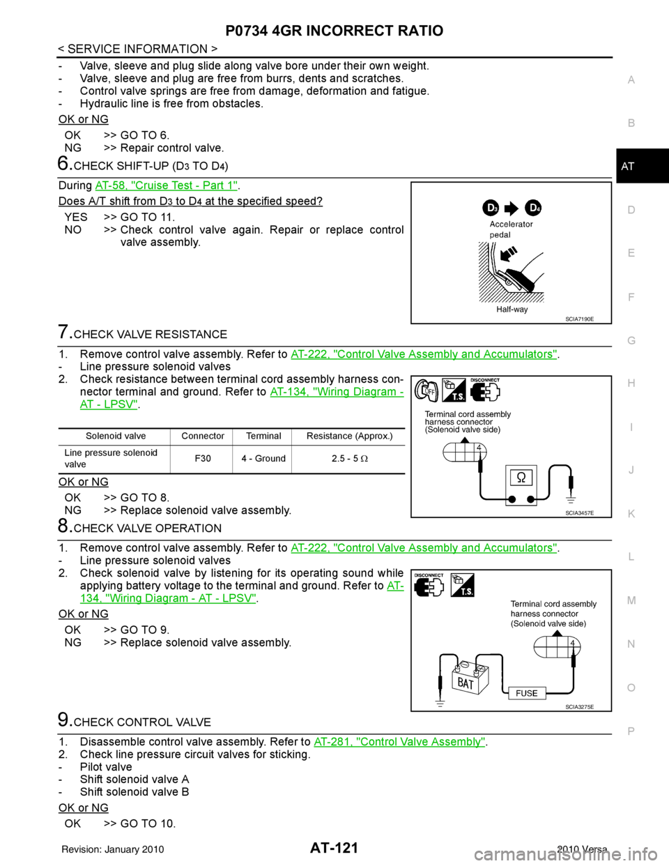
1. Remove control valve assembly. Refer to AT-222, "
Control Valve Assembly and Accumulators".
- Line pressure solenoid valves
2. Check resistance between terminal cord assembly harness con- nector terminal and ground. Refer to AT-134, "
Wiring Diagram -
AT - L P S V".
OK or NG
OK >> GO TO 8.
NG >> Replace solenoid valve assembly.
8.CHECK VALVE OPERATION
1. Remove control valve assembly. Refer to AT-222, "
Control Valve Assembly and Accumulators".
- Line pressure solenoid valves
2. Check solenoid valve by listening for its operating sound while applying battery voltage to the terminal and ground. Refer to AT-
134, "Wiring Diagram - AT - LPSV".
OK or NG
OK >> GO TO 9.
NG >> Replace solenoid valve assembly.
9.CHECK CONTROL VALVE
1. Disassemble control valve assembly. Refer to AT-281, "
Control Valve Assembly".
2. Check line pressure circuit valves for sticking.
- Pilot valve
- Shift solenoid valve A
- Shift solenoid valve B
OK or NG
OK >> GO TO 10.
SCIA7190E
Solenoid valve Connector Terminal Resistance (Approx.)
Line pressure solenoid
valve F30 4 - Ground 2.5 - 5
Ω
SCIA3457E
SCIA3275E
Revision: January 20102010 Versa
Page 146 of 3745
P0744 TORQUE CONVERTERAT-129
< SERVICE INFORMATION >
DE
F
G H
I
J
K L
M A
B
AT
N
O P
5. Accelerate vehicle to more than 80 km/h (50 MPH) and maintain the following conditions continuously until “TESTING” has turned to “COMPLETE”. (It will take approximately 30 seconds after “TESTING”
shows.)
THROTTLE POSI: 1.0/8 - 2.0/8 (a t all times during step 4)
SLCT LVR POSI: “D” position
TCC S/V DUTY: More than 94%
VEHICLE SPEED: Constant speed of more than 80 km/h (50 MPH)
- Make sure that “GEAR” shows “4”.
- For shift schedule, refer to AT-64, "
Vehicle Speed at Which Gear Shifting Occurs".
- If “TESTING” does not appear on CONSULT-III for a long time, select “SELF-DIAG RESULTS”. In
case a DTC other than “P0744 T/C CLUT CH FNCTN” is shown, refer to AT- 7 7 , "
CONSULT-III Func-
tion (TRANSMISSION)".
6. Make sure that “OK” is disp layed. (If “NG” is displayed, refer to “DIAGNOSTIC PROCEDURE”.)
Refer to AT-129, "
Diagnosis Procedure".
Refer to AT-64, "
Vehicle Speed at Which Lock-up Occurs/Releases".
WITH GST
Follow the procedure “WITH CONSULT-III”.
Diagnosis ProcedureINFOID:0000000005397323
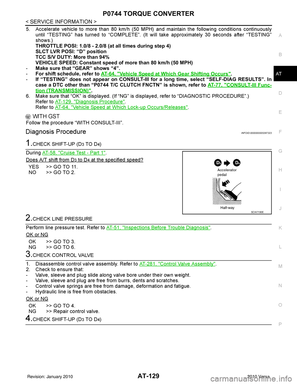
1.CHECK SHIFT-UP (D3 TO D4)
During AT-58, "
Cruise Test - Part 1".
Does A/T shift from D
3 to D4 at the specified speed?
YES >> GO TO 11.
NO >> GO TO 2.
2.CHECK LINE PRESSURE
Perform line pressure test. Refer to AT-51, "
Inspections Before Trouble Diagnosis".
OK or NG
OK >> GO TO 3.
NG >> GO TO 6.
3.CHECK CONTROL VALVE
1. Disassemble control valve assembly. Refer to AT-281, "
Control Valve Assembly".
2. Check to ensure that:
- Valve, sleeve and plug slide along valve bore under their own weight.
- Valve, sleeve and plug are free from burrs, dents and scratches.
- Control valve springs are free from damage, deformation and fatigue.
- Hydraulic line is free from obstacles.
OK or NG
OK >> GO TO 4.
NG >> Repair control valve.
4.CHECK SHIFT-UP (D3 TO D4)
SCIA7190E
Revision: January 20102010 Versa
Page 526 of 3745
HOODBL-17
< SERVICE INFORMATION >
C
DE
F
G H
J
K L
M A
B
BL
N
O P
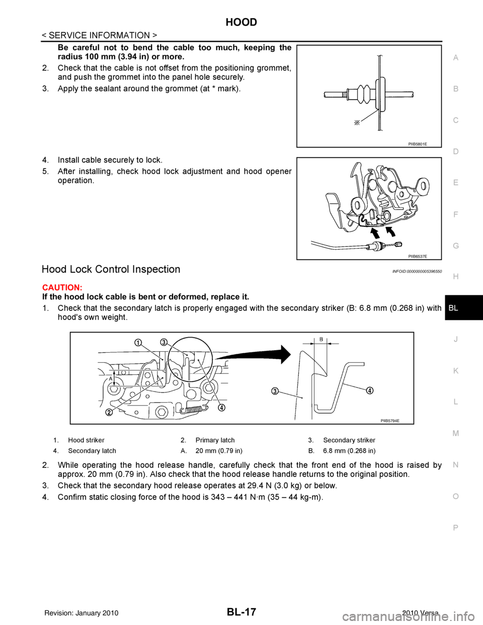
Be careful not to bend the cable too much, keeping the
radius 100 mm (3.94 in) or more.
2. Check that the cable is not of fset from the positioning grommet,
and push the grommet into the panel hole securely.
3. Apply the sealant around the grommet (at * mark).
4. Install cable securely to lock.
5. After installing, check hood lock adjustment and hood opener operation.
Hood Lock Control InspectionINFOID:0000000005396550
CAUTION:
If the hood lock cable is bent or deformed, replace it.
1. Check that the secondary latch is properly engaged with the secondary striker (B: 6.8 mm (0.268 in) with
hood's own weight.
2. While operating the hood release handle, carefully check that the front end of the hood is raised by
approx. 20 mm (0.79 in). Also check that the hood release handle returns to the original position.
3. Check that the secondary hood release operates at 29.4 N (3.0 kg) or below.
4. Confirm static closing force of the hood is 343 – 441 N·m (35 – 44 kg-m).
PIIB5801E
PIIB6537E
1. Hood striker 2. Primary latch 3. Secondary striker
4. Secondary latch A. 20 mm (0.79 in) B. 6.8 mm (0.268 in)
PIIB5794E
Revision: January 20102010 Versa
Page 672 of 3745
DOOR
BL-163
< SERVICE INFORMATION >
C
D E
F
G H
J
K L
M A
B
BL
N
O P
Removal and InstallationINFOID:0000000005396645
FRONT DOOR
CAUTION:
• When removing and installing the front door assembly, support the door with a jack and cloth to pro-
tect the door and body.
• When removing and installing front door assembly, be sure to carry out the fitting adjustment. Refer
to BL-160, "
Fitting Adjustment".
• After installing, apply touch-up pain t onto the head of the hinge nuts.
• Check the hinge rotating pa rt for lubrication. If necessary, apply “body grease”.
• Operate with two workers, because of its heavy weight.
• Check front door open/close op eration after installation.
Removal
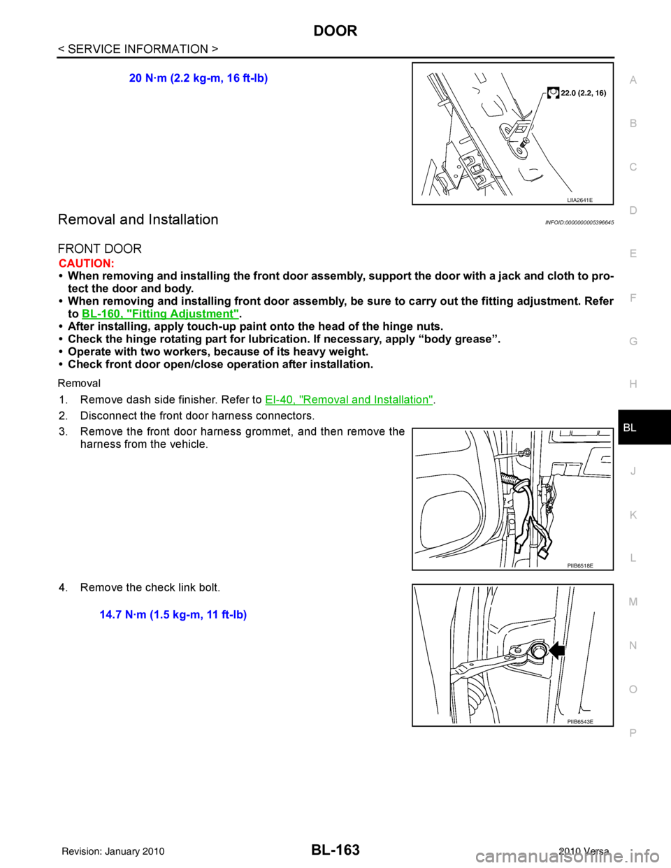
1. Remove dash side finisher. Refer to EI-40, "Removal and Installation".
2. Disconnect the front door harness connectors.
3. Remove the front door harness grommet, and then remove the harness from the vehicle.
4. Remove the check link bolt. 20 N·m (2.2 kg-m, 16 ft-lb)
LIIA2641E
PIIB6518E
14.7 N·m (1.5 kg-m, 11 ft-lb)
PIIB6543E
Revision: January 20102010 Versa
Page 673 of 3745
BL-164
< SERVICE INFORMATION >
DOOR
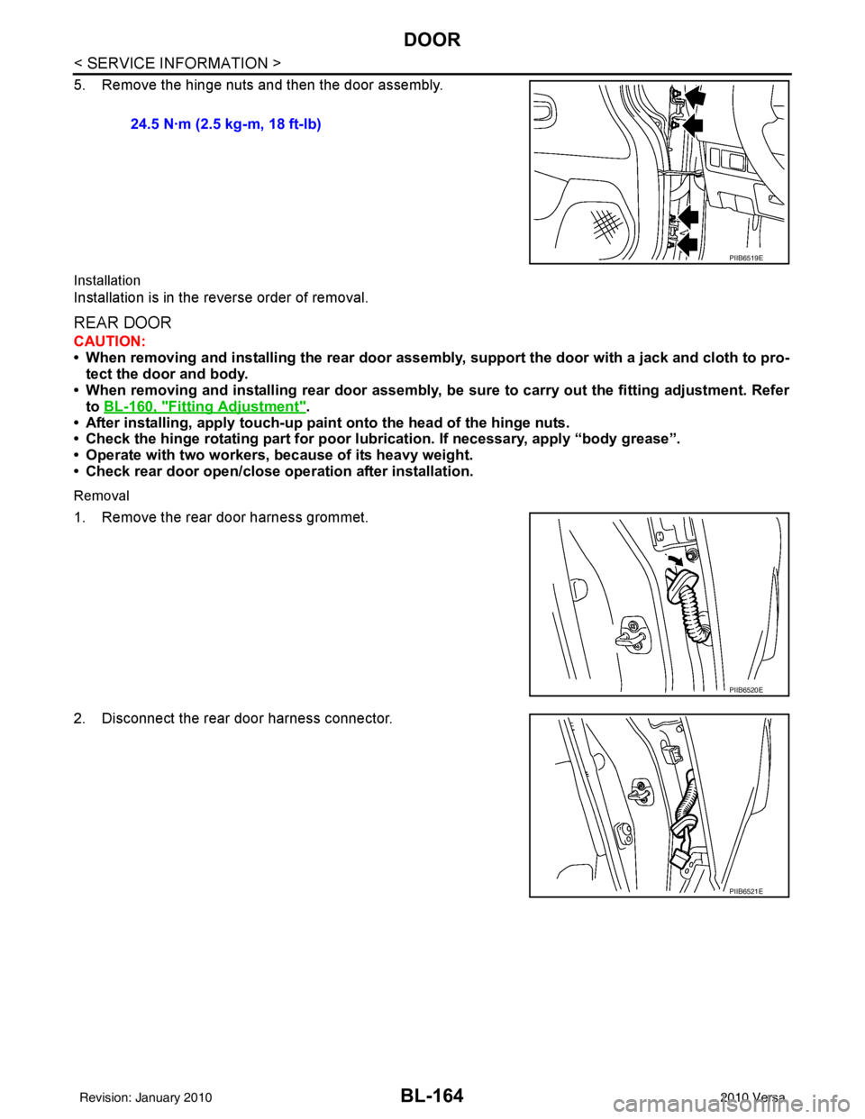
5. Remove the hinge nuts and then the door assembly.
Installation
Installation is in the reverse order of removal.
REAR DOOR
CAUTION:
• When removing and installing the rear door assembly, support the door with a jack and cloth to pro-
tect the door and body.
• When removing and installing rear door assembly, be sure to carry out the fitting adjustment. Refer
to BL-160, "
Fitting Adjustment".
• After installing, apply touch-up paint onto the head of the hinge nuts.
• Check the hinge rotating part for poor lubrication. If necessary, apply “body grease”.
• Operate with two workers, because of its heavy weight.
• Check rear door open/close operation after installation.
Removal
1. Remove the rear door harness grommet.
2. Disconnect the rear door harness connector. 24.5 N·m (2.5 kg-m, 18 ft-lb)
PIIB6519E
PIIB6520E
PIIB6521E
Revision: January 20102010 Versa
Page 816 of 3745
BODY REPAIRBL-307
< SERVICE INFORMATION >
C
DE
F
G H
J
K L
M A
B
BL
N
O P
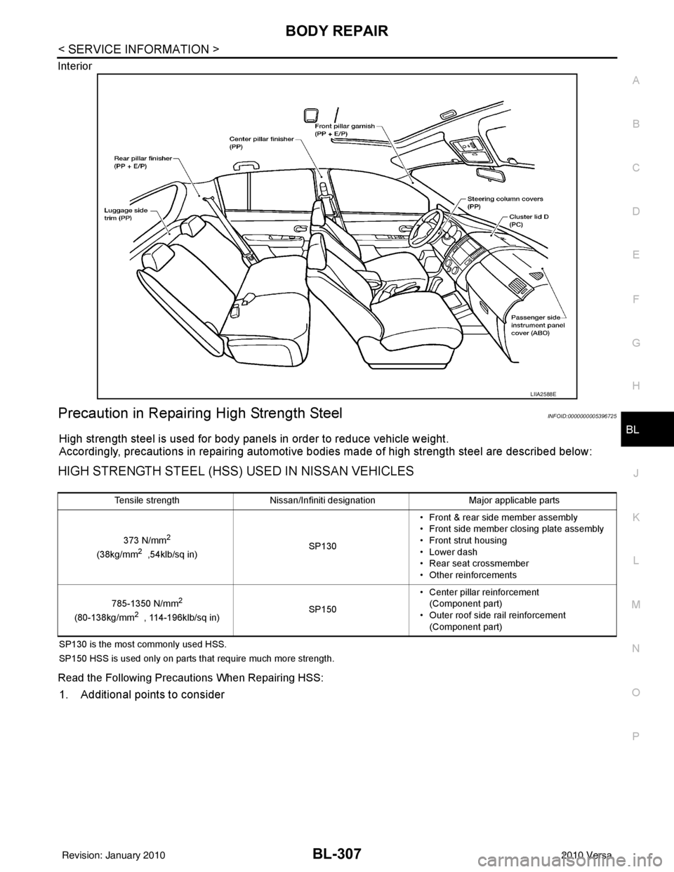
Interior
Precaution in Repairing High Strength SteelINFOID:0000000005396725
High strength steel is used for body panels in order to reduce vehicle weight.
Accordingly, precautions in repairing automotive bodies made of high strength steel are described below:
HIGH STRENGTH STEEL (HSS) USED IN NISSAN VEHICLES
SP130 is the most commonly used HSS.
SP150 HSS is used only on parts that require much more strength.
Read the Following Precautions When Repairing HSS:
1. Additional points to consider
LIIA2588E
Tensile strength
Nissan/Infiniti designation Major applicable parts
373 N/mm
2
(38kg/mm2 ,54klb/sq in) SP130• Front & rear side member assembly
• Front side member closing plate assembly
• Front strut housing
• Lower dash
• Rear seat crossmember
• Other reinforcements
785-1350 N/mm
2
(80-138kg/mm2 , 114-196klb/sq in) SP150• Center pillar reinforcement
(Component part)
• Outer roof side rail reinforcement (Component part)
Revision: January 20102010 Versa