NISSAN TIIDA 2010 Service Repair Manual
Manufacturer: NISSAN, Model Year: 2010, Model line: TIIDA, Model: NISSAN TIIDA 2010Pages: 3745, PDF Size: 73.67 MB
Page 771 of 3745
BL-262
< SERVICE INFORMATION >
NATS (NISSAN ANTI-THEFT SYSTEM)
5.REPLACE BCM
1. Replace BCM. Refer to BCS-19, "
Removal and Installation of BCM".
2. Perform initialization with CONSULT-III.
For initialization, refer to “CONSULT-III Operation Manual NATS”.
Does the engine start?
Yes >> BCM is malfunctioning. • Replace BCM. Refer to BCS-19, "
Removal and Installation of BCM" .
• Perform initialization with CONSULT-III
• For initialization, refer to “CONSULT-III Operation Manual NATS”
No >> ECM is malfunctioning. • Replace ECM.
• Perform initialization or re-communicating function
• For initialization, refer to “CONSULT-III Operation Manual NATS”
• For re-communicating function, refer to BL-249, "
ECM Re-communicating Function"
Diagnosis Procedure 2INFOID:0000000005396712
Self-diagnostic results:
“CHAIN OF IMMU-KEY” displayed on CONSULT-III screen
1.CONFIRM SELF-DIAGNOSTIC RESULTS
Confirm SELF-DIAGNOSTIC RESULTS “CHAIN OF IMMU-KEY” displayed on CONSULT-III screen.
Is
“CHAIN OF IMMU-KEY” displayed?
Ye s > > G O T O 2
No >> GO TO BL-259, "
Trouble Diagnosis" .
2.CHECK NATS ANTENNA AMP. INSTALLATION
Check NATS antenna amp. installation. Refer to BL-266, "
How to Replace NATS Antenna Amp" .
OK or NG
OK >> GO TO 3
NG >> Reinstall NATS antenna amp. correctly.
3.CHECK NATS IGNITION KEY ID CHIP
Start engine with another registered NATS ignition key.
Does the engine start?
Yes >> Ignition key ID chip is malfunctioning. • Replace the ignition key
• Perform initialization with CONSULT-IIIFor initialization, refer to “CONSULT-III Operation Manual NATS”
No >> GO TO 4
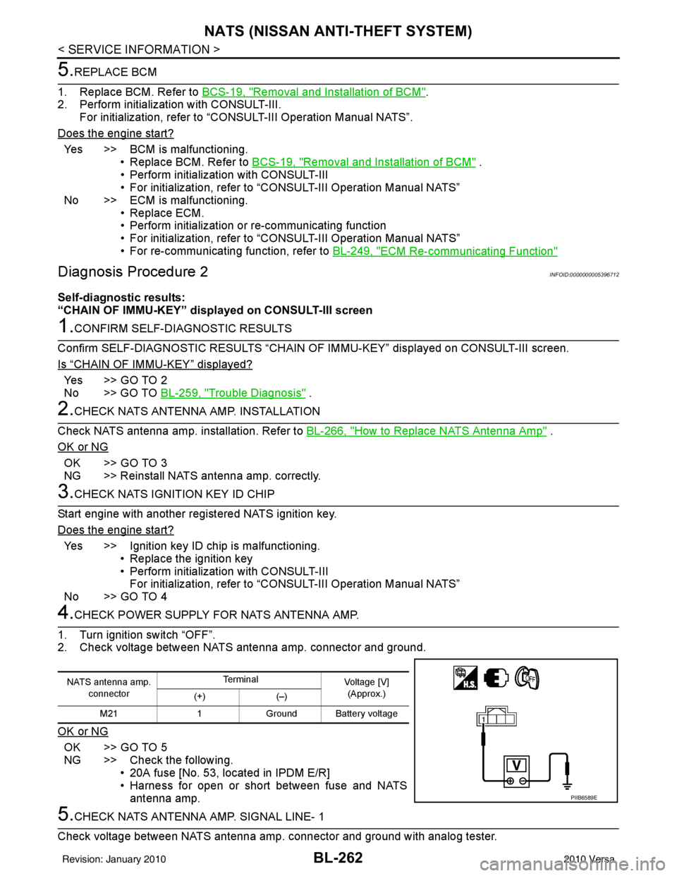
4.CHECK POWER SUPPLY FO R NATS ANTENNA AMP.
1. Turn ignition switch “OFF”.
2. Check voltage between NATS antenna amp. connector and ground.
OK or NG
OK >> GO TO 5
NG >> Check the following. • 20A fuse [No. 53, located in IPDM E/R]
• Harness for open or short between fuse and NATSantenna amp.
5.CHECK NATS ANTENNA AMP. SIGNAL LINE- 1
Check voltage between NATS antenna amp. connector and ground with analog tester.
NATS antenna amp. connector Te r m i n a l
Voltage [V]
(Approx.)
(+) (–)
M21 1Ground Battery voltage
PIIB6589E
Revision: January 20102010 Versa
Page 772 of 3745
NATS (NISSAN ANTI-THEFT SYSTEM)BL-263
< SERVICE INFORMATION >
C
DE
F
G H
J
K L
M A
B
BL
N
O P
OK or NG
OK >> GO TO 6
NG >> • Check harness for open or short between NATS antenna amp. and BCM. NOTE:
If harness is OK, replace BCM, perform initialization with CONSULT-III. For initialization, refer to
“CONSULT-III Operation Manual NATS”.
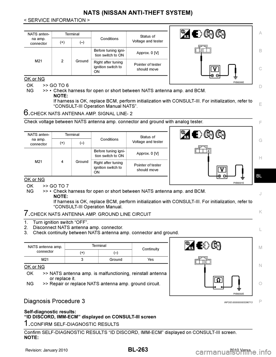
6.CHECK NATS ANTENNA AMP. SIGNAL LINE- 2
Check voltage between NATS antenna amp. connector and ground with analog tester.
OK or NG
OK >> GO TO 7
NG >> • Check harness for open or short between NATS antenna amp. and BCM. NOTE:
If harness is OK, replace BCM, perform initialization with CONSULT-III. For initialization, refer to
“CONSULT-III Operation Manual.
7.CHECK NATS ANTENNA AMP. GROUND LINE CIRCUIT
1. Turn ignition switch “OFF”.
2. Disconnect NATS antenna amp. connector.
3. Check continuity between NATS antenna amp. connector and ground.
OK or NG
OK >> NATS antenna amp. is malfunctioning, reinstall antenna or replace it.
NG >> Repair or replace NATS antenna amp. ground circuit.
Diagnosis Procedure 3INFOID:0000000005396713
Self-diagnostic results:
“ID DISCORD, IMM-ECM” disp layed on CONSULT-III screen
1.CONFIRM SELF-DIAGNOSTIC RESULTS
Confirm SELF-DIAGNOSTIC RESULTS “ID DISCO RD, IMM-ECM” displayed on CONSULT-III screen.
NOTE:
NATS anten-
na amp.
connector Te r m i n a l
Conditions Status of
Voltage and tester
(+) (–)
M21 2 Ground Before tuning igni-
tion switch to ON Approx. 0 [V]
Right after tuning
ignition switch to
ON Pointer of tester
should move
PIIB6590E
NATS anten- na amp.
connector Te r m i n a l
Conditions Status of
Voltage and tester
(+) (–)
M21 4 Ground Before tuning igni-
tion switch to ON Approx. 0 [V]
Right after tuning
ignition switch to
ON Pointer of tester
should move
PIIB6591E
NATS antenna amp.
connector Te r m i n a l
Continuity
(+) (–)
M21 3Ground Yes
PIIB6592E
Revision: January 20102010 Versa
Page 773 of 3745
BL-264
< SERVICE INFORMATION >
NATS (NISSAN ANTI-THEFT SYSTEM)
“ID DISCORD IMM-ECM”:
Registered ID of BCM is in discord with that of ECM.
Is
“ID DISCORD IMM-ECM” displayed?
Ye s > > G O T O 2
No >> GO TO BL-259, "
Trouble Diagnosis" .
2.PERFORM INITIALIZATION WITH CONSULT-III
Perform initialization with CONSULT-III. Re-register all NATS ignition key IDs.
For initialization, refer to “CONSULT-III Operation Manual NATS”.
NOTE:
If the initialization is not completed or ma lfunctions, CONSULT-III shows message on the screen.
Can the system be initialized?
Yes >> • Start engine. (END) • (System initialization had not been completed.)
No >> ECM is malfunctioning. • Replace ECM.
• Perform initialization with CONSULT-III
For initialization, refer to “CONSULT-III Operation Manual NATS”
Diagnosis Procedure 4INFOID:0000000005396714
“COMBINATION METER (SECURITY) DOES NOT LIGHT UP”
1.CHECK FUSE
Check 10A fuse [No.13, located in the fuse block (J/B)]
OK or NG
OK >> GO TO 2
NG >> Replace fuse.
2.CHECK COMBINATION METER (SECURITY)
1. Install 10A fuse.
2. Start engine and turn ignition switch OFF.
3. Check if the combination meter (security) lights up.
OK or NG
OK >> Inspection End.
NG >> GO TO 3
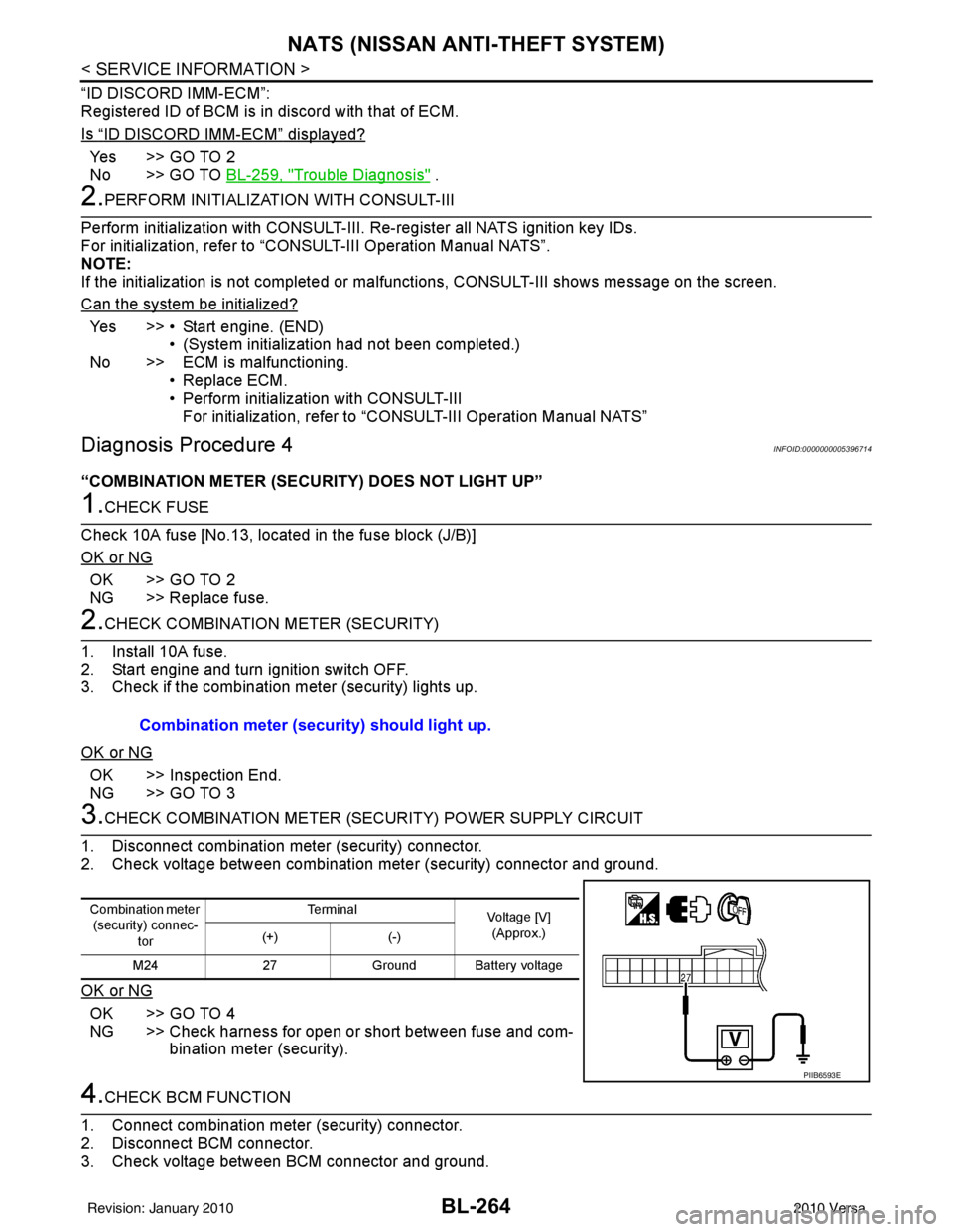
3.CHECK COMBINATION METER (SECURITY) POWER SUPPLY CIRCUIT
1. Disconnect combination meter (security) connector.
2. Check voltage between combination meter (security) connector and ground.
OK or NG
OK >> GO TO 4
NG >> Check harness for open or short between fuse and com- bination meter (security).
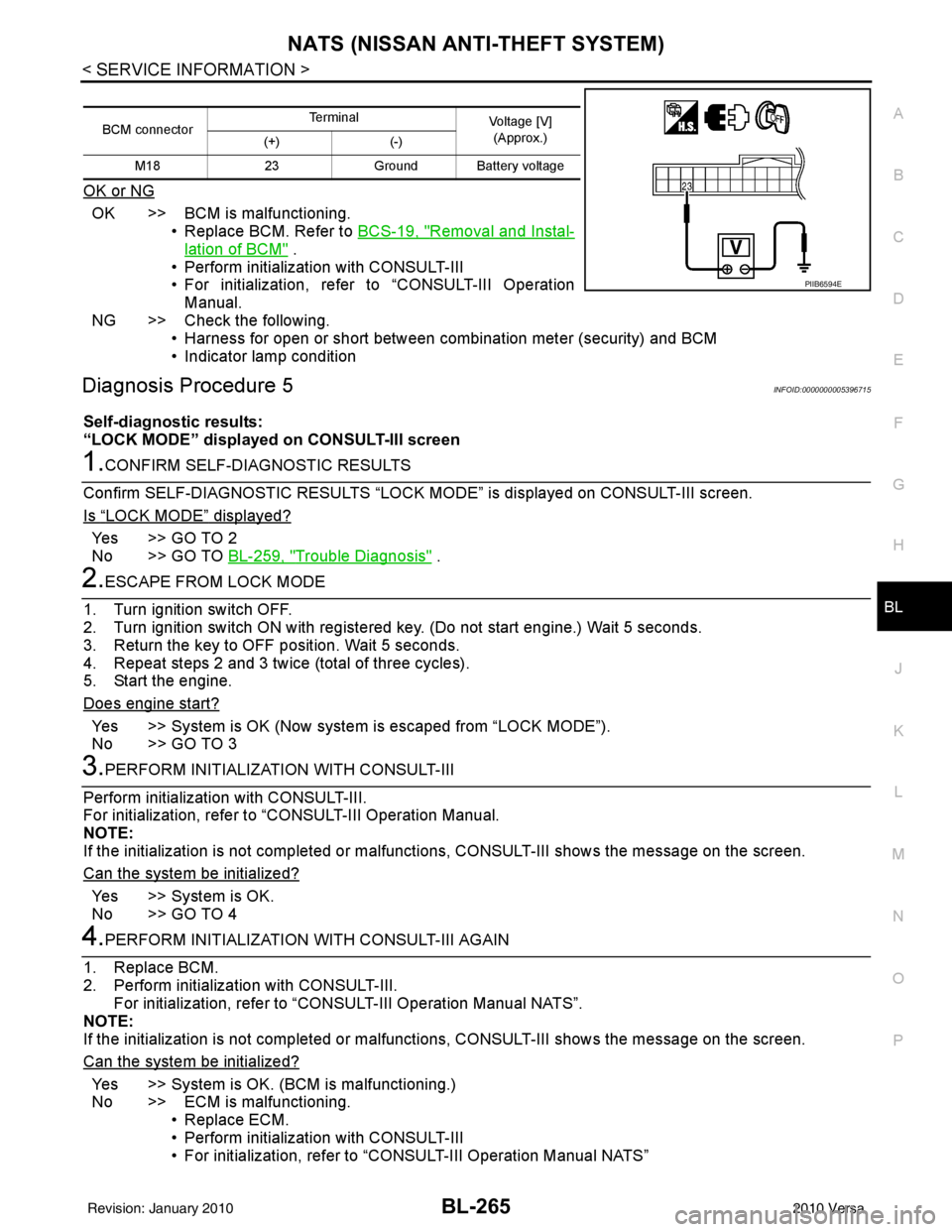
4.CHECK BCM FUNCTION
1. Connect combination meter (security) connector.
2. Disconnect BCM connector.
3. Check voltage between BCM connector and ground. Combination meter (security) should light up.
Combination meter
(security) connec-
tor Te r m i n a l
Voltage [V]
(Approx.)
(+) (-)
M24 27Ground Battery voltage
PIIB6593E
Revision: January 20102010 Versa
Page 774 of 3745
NATS (NISSAN ANTI-THEFT SYSTEM)BL-265
< SERVICE INFORMATION >
C
DE
F
G H
J
K L
M A
B
BL
N
O P
OK or NG
OK >> BCM is malfunctioning. • Replace BCM. Refer to BCS-19, "
Removal and Instal-
lation of BCM" .
• Perform initialization with CONSULT-III
• For initialization, refer to “CONSULT-III Operation Manual.
NG >> Check the following. • Harness for open or short between combination meter (security) and BCM
• Indicator lamp condition
Diagnosis Procedure 5INFOID:0000000005396715
Self-diagnostic results:
“LOCK MODE” displayed on CONSULT-III screen
1.CONFIRM SELF-DIAGNOSTIC RESULTS
Confirm SELF-DIAGNOSTIC RESULTS “LOCK MODE” is displayed on CONSULT-III screen.
Is
“LOCK MODE” displayed?
Yes >> GO TO 2
No >> GO TO BL-259, "
Trouble Diagnosis" .
2.ESCAPE FROM LOCK MODE
1. Turn ignition switch OFF.
2. Turn ignition switch ON with registered key. (Do not start engine.) Wait 5 seconds.
3. Return the key to OFF position. Wait 5 seconds.
4. Repeat steps 2 and 3 twice (total of three cycles).
5. Start the engine.
Does engine start?
Yes >> System is OK (Now system is escaped from “LOCK MODE”).
No >> GO TO 3
3.PERFORM INITIALIZATION WITH CONSULT-III
Perform initialization with CONSULT-III.
For initialization, refer to “CONSULT-III Operation Manual.
NOTE:
If the initialization is not completed or malf unctions, CONSULT-III shows the message on the screen.
Can the system be initialized?
Yes >> System is OK.
No >> GO TO 4
4.PERFORM INITIALIZATION WITH CONSULT-III AGAIN
1. Replace BCM.
2. Perform initialization with CONSULT-III. For initialization, refer to “CON SULT-III Operation Manual NATS”.
NOTE:
If the initialization is not completed or malf unctions, CONSULT-III shows the message on the screen.
Can the system be initialized?
Yes >> System is OK. (BCM is malfunctioning.)
No >> ECM is malfunctioning. • Replace ECM.
• Perform initialization with CONSULT-III
• For initialization, refer to “CONSULT-III Operation Manual NATS”
BCM connector Terminal
Voltage [V]
(Approx.)
(+) (-)
M18 23Ground Battery voltage
PIIB6594E
Revision: January 20102010 Versa
Page 775 of 3745
BL-266
< SERVICE INFORMATION >
NATS (NISSAN ANTI-THEFT SYSTEM)
Diagnosis Procedure 6
INFOID:0000000005396716
Self-diagnostic results:
“DIFFERENCE OF KEY” disp layed on CONSULT-III screen
1.CONFIRM SELF-DIAGNOSTIC RESULTS
Confirm SELF-DIAGNOSTIC RESU LTS “DIFFERENCE OF KEY” displayed on CONSULT-III screen.
Is
“DIFFERENCE OF KEY” displayed?
YES >> GO TO 2
NO >> GO TO BL-259, "
Trouble Diagnosis".
2.PERFORM INITIALIZATION WITH CONSULT-III
Perform initialization with CONSULT-III. Re-register all NATS ignition key IDs.
For initialization and registration of NATS ignition key IDs, refer to CONSULT-III Operation Manual.
NOTE:
If the initialization is not completed or ma lfunctions, CONSULT-III shows message on the screen.
Can the system be initialized and can the engine be started with re-registered NATS ignition key?
YES >> • Ignition key ID was unregistered.
NO >> • BCM is malfunctioning. • Replace BCM. Refer to BCS-19, "
Removal and Installation of BCM".
• Perform initialization with CONSULT-III.
• For initialization, refer to CONSULT-III Operation Manual.
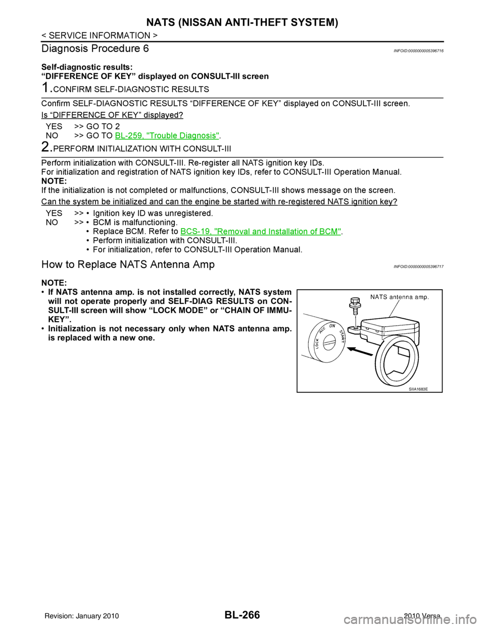
How to Replace NATS Antenna AmpINFOID:0000000005396717
NOTE:
• If NATS antenna amp. is not installed correctly, NATS system
will not operate properly and SELF-DIAG RESULTS on CON-
SULT-III screen will show “LOCK MODE” or “CHAIN OF IMMU-
KEY”.
• Initialization is not necessary only when NATS antenna amp.
is replaced with a new one.
SIIA1683E
Revision: January 20102010 Versa
Page 776 of 3745
BODY REPAIRBL-267
< SERVICE INFORMATION >
C
DE
F
G H
J
K L
M A
B
BL
N
O P
BODY REPAIR
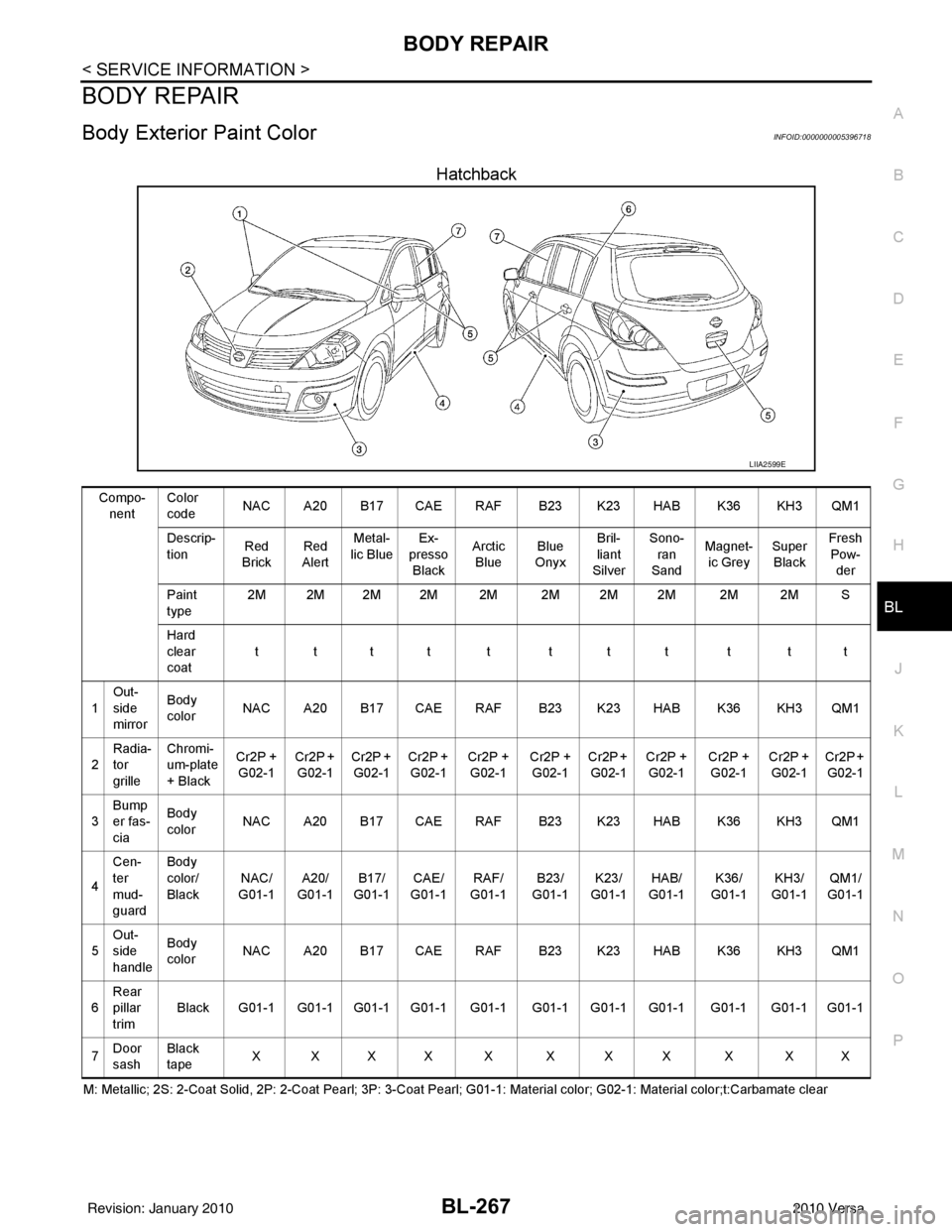
Body Exterior Paint ColorINFOID:0000000005396718
Hatchback
M: Metallic; 2S: 2-Coat Solid, 2P: 2-Coat Pearl; 3P: 3-Coat Pearl; G01-1: Material color; G02-1: Material color;t:Carbamate cle ar
LIIA2599E
Compo-
nent Color
code
NAC A20 B17 CAE RAF B23 K23 HAB K36 KH3 QM1
Descrip-
tion Red
Brick Red
Alert Metal-
lic Blue Ex-
presso
Black Arctic
Blue Blue
Onyx Bril-
liant
Silver Sono-
ran
Sand Magnet-
ic Grey Super
Black Fresh
Pow-
der
Paint
type 2M 2M 2M 2M 2M 2M 2M 2M 2M 2M S
Hard
clear
coat tttt t ttt t tt
1 Out-
side
mirror Body
color
NAC A20 B17 CAE RAF B23 K23 HAB K36 KH3 QM1
2 Radia-
tor
grille Chromi-
um-plate
+ Black
Cr2P +
G02-1 Cr2P +
G02-1 Cr2P +
G02-1 Cr2P +
G02-1 Cr2P +
G02-1 Cr2P +
G02-1 Cr2P +
G02-1 Cr2P +
G02-1 Cr2P +
G02-1 Cr2P +
G02-1 Cr2P +
G02-1
3 Bump
er fas-
cia Body
color
NAC A20 B17 CAE RAF B23 K23 HAB K36 KH3 QM1
4 Cen-
ter
mud-
guard Body
color/
Black
NAC/
G01-1 A20/
G01-1 B17/
G01-1 CAE/
G01-1 RAF/
G01-1 B23/
G01-1 K23/
G01 -
1 HAB/
G01-1 K36/
G01-1 KH3/
G01-1 QM1/
G01-1
5 Out-
side
handle Body
color
NAC A20 B17 CAE RAF B23 K23 HAB K36 KH3 QM1
6 Rear
pillar
trim Black G01-1 G01-1 G01-1 G01-1 G01-1 G01-1 G01-1 G01-1 G01-1 G01-1 G01-1
7 Door
sash Black
tape
XXXX X XXX X XX
Revision: January 20102010 Versa
Page 777 of 3745
BL-268
< SERVICE INFORMATION >
BODY REPAIR
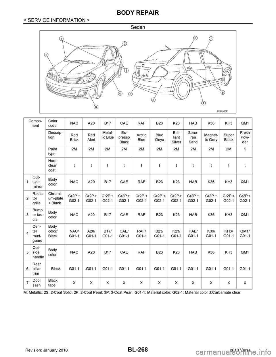
Sedan
M: Metallic; 2S: 2-Coat Solid, 2P: 2-Coat Pearl; 3P: 3-Coat Pearl; G01-1: Material color; G02-1: Material color ;t:Carbamate clear
LIIA2883E
Compo-
nent Color
code
NAC A20 B17 CAE RAF B23 K23 HAB K36 KH3 QM1
Descrip-
tion Red
Brick Red
Alert Metal-
lic Blue Ex-
presso
Black Arctic
Blue Blue
Onyx Bril-
liant
Silver Sono-
ran
Sand Magnet-
ic Grey Super
Black Fresh
Pow-
der
Paint
type 2M 2M 2M 2M 2M 2M 2M 2M 2M 2M S
Hard
clear
coat tttt t ttt t tt
1 Out-
side
mirror Body
color
NAC A20 B17 CAE RAF B23 K23 HAB K36 KH3 QM1
2 Radia-
tor
grille Chromi-
um-plate
+ Black
Cr2P +
G02-1 Cr2P +
G02-1 Cr2P +
G02-1 Cr2P +
G02-1 Cr2P +
G02-1 Cr2P +
G02-1 Cr2P +
G02-1 Cr2P +
G02-1 Cr2P +
G02-1 Cr2P +
G02-1 Cr2P +
G02-1
3 Bump
er fas-
cia Body
color
NAC A20 B17 CAE RAF B23 K23 HAB K36 KH3 QM1
4 Cen-
ter
mud-
guard Body
color/
Black
NAC/
G01-1 A20/
G01-1 B17/
G01-1 CAE/
G01-1 RAF/
G01-1 B23/
G01-1 K23/
G0 1-
1 HAB/
G01-1 K36/
G01-1 KH3/
G01-1 QM1/
G01-1
5 Out-
side
handle Body
color
NAC A20 B17 CAE RAF B23 K23 HAB K36 KH3 QM1
6 Rear
pillar
trim Black G01-1 G01-1 G01-1 G01-1 G01-1 G01-1 G01-1 G01-1 G01-1 G01-1 G01-1
7 Door
sash Black
tape
XXXX X XXX X XX
Revision: January 20102010 Versa
Page 778 of 3745
BODY REPAIRBL-269
< SERVICE INFORMATION >
C
DE
F
G H
J
K L
M A
B
BL
N
O P
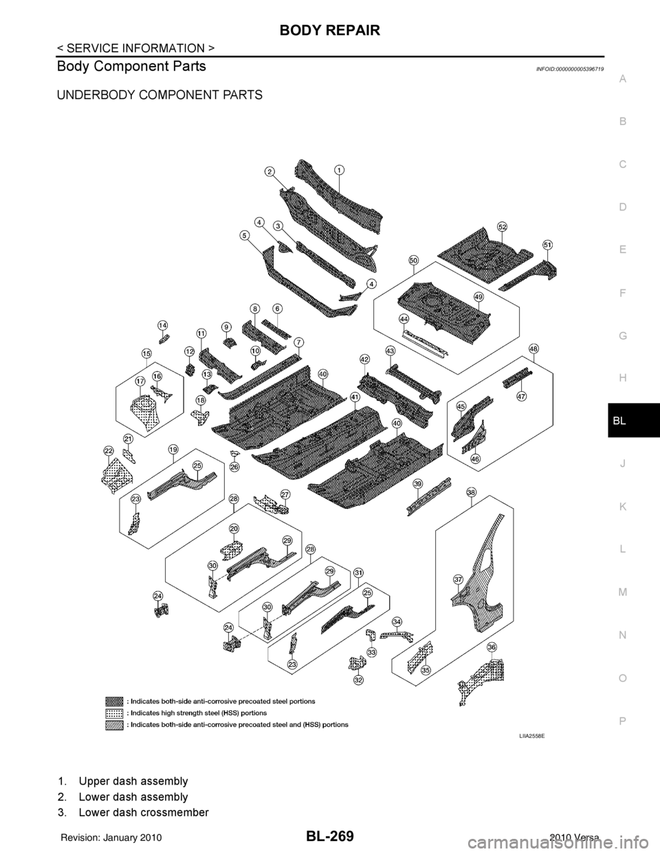
Body Component PartsINFOID:0000000005396719
UNDERBODY COMPONENT PARTS
1. Upper dash assembly
2. Lower dash assembly
3. Lower dash crossmember
LIIA2558E
Revision: January 20102010 Versa
Page 779 of 3745

BL-270
< SERVICE INFORMATION >
BODY REPAIR
4. Front pillar inner reinforcement (RH&LH)
5. Lower dash reinforcement
6. 4th crossmember (RH&LH)
7. Front side member rear extension (RH&LH)
8. 3rd crossmember (RH&LH)
9. Front seat outer rear bracket (RH&LH)
10. Front seat inner rear bracket (RH&LH)
11. 2nd crossmember (RH&LH)
12. Front seat outer front bracket (RH&LH)
13. Front seat inner front bracket (RH&LH)
14. Fender bracket (RH&LH)
15. Strut housing assembly RH
16. Cowl top side upper (RH&LH)
17. Front strut housing (RH&LH)
18. Upper torque rod reinforcement
19. Closing plate assembly RH
20. Engine mount reinforcement
21. Strut tower front reinforcement RH
22. Front hoodledge lower RH
23. Frame bracket outer (RH&LH)
24. Front bumper support bracket (RH&LH)
25. Closing plate (RH&LH)
26. Front suspension rear bracket (RH&LH)
27. Front side member outrigger (RH&LH)
28. Front side member assembly (RH&LH)
29. Front side member (RH&LH)
30. Frame bracket (RH&LH)
31. Closing plate assembly LH
32. Hoodledge connector (RH&LH)
33. Radiator core side support (RH&LH)
34. Radiator core support upper (RH&LH)
35. Hoodledge upper (RH&LH)
36. Hoodledge reinforcement assembly (RH&LH)
37. Dash side (RH&LH)
38. Dash side assembly (RH& LH)
39. Front floor reinforcement (RH&LH)
40. Front floor front (RH&LH)
41. Front floor center
42. Rear seat crossmember
43. Rear center crossmember
44. Rear seat upper crossmember
45. Rear side member (RH&LH)
46. Sill inner extension (RH&LH)
47. Rear side member extension (RH&LH)
48. Rear side member assembly (RH & LH)
49. Rear floor front
50. Rear floor front assembly
51. Rear floor side (RH&LH)
52. Rear floor rear
Revision: January 20102010 Versa
Page 780 of 3745
BODY REPAIRBL-271
< SERVICE INFORMATION >
C
DE
F
G H
J
K L
M A
B
BL
N
O P
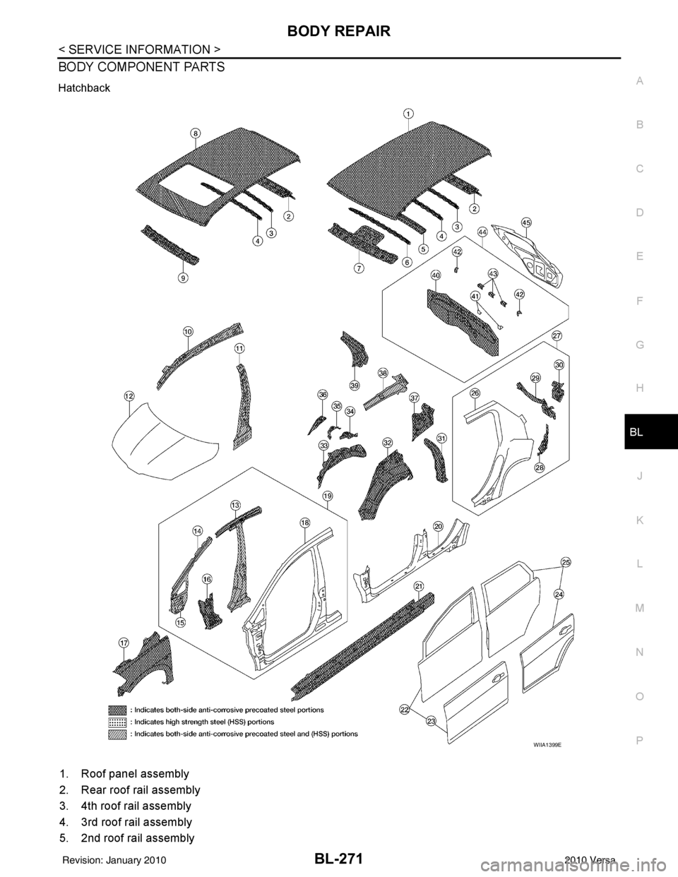
BODY COMPONENT PARTS
Hatchback
1. Roof panel assembly
2. Rear roof rail assembly
3. 4th roof rail assembly
4. 3rd roof rail assembly
5. 2nd roof rail assembly
WIIA1399E
Revision: January 20102010 Versa