Lt-26 NISSAN TIIDA 2010 Service Repair Manual
[x] Cancel search | Manufacturer: NISSAN, Model Year: 2010, Model line: TIIDA, Model: NISSAN TIIDA 2010Pages: 3745, PDF Size: 73.67 MB
Page 528 of 3745
RADIATOR CORE SUPPORTBL-19
< SERVICE INFORMATION >
C
DE
F
G H
J
K L
M A
B
BL
N
O P
RADIATOR CORE SUPPORT
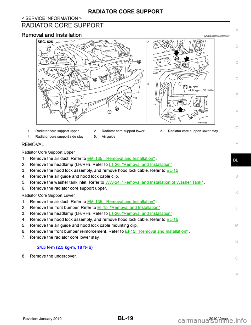
Removal and InstallationINFOID:0000000005396551
REMOVAL
Radiator Core Support Upper
1. Remove the air duct. Refer to EM-135, "Removal and Installation" .
2. Remove the headlamp (LH/RH). Refer to LT-26, "
Removal and Installation" .
3. Remove the hood lock assembly, and remove hood lock cable. Refer to BL-15
.
4. Remove the air guide and hood lock cable clip.
5. Remove the washer tank inlet. Refer to WW-24, "
Removal and Installation of Washer Tank" .
6. Remove the radiator core support upper.
Radiator Core Support Lower
1. Remove the air duct. Refer to EM-135, "Removal and Installation" .
2. Remove the front bumper. Refer to EI-15, "
Removal and Installation" .
3. Remove the headlamp (LH/RH). Refer to LT-26, "
Removal and Installation" .
4. Remove the hood lock assembly, and remove hood lock cable. Refer to BL-15
.
5. Remove the air guide and hood lock cable mounting clip.
6. Remove the front bumper reinforcement. Refer to EI-15, "
Removal and Installation" .
7. Remove the radiator core lower stay.
8. Remove the undercover.
PIIB6515E
1. Radiator core support upper 2. Radiator core support lower 3. Radiator core support lower stay
4. Radiator core support side stay 5. Air guide
24.5 N·m (2.5 kg-m, 18 ft-lb)
Revision: January 20102010 Versa
Page 530 of 3745
FRONT FENDERBL-21
< SERVICE INFORMATION >
C
DE
F
G H
J
K L
M A
B
BL
N
O P
FRONT FENDER
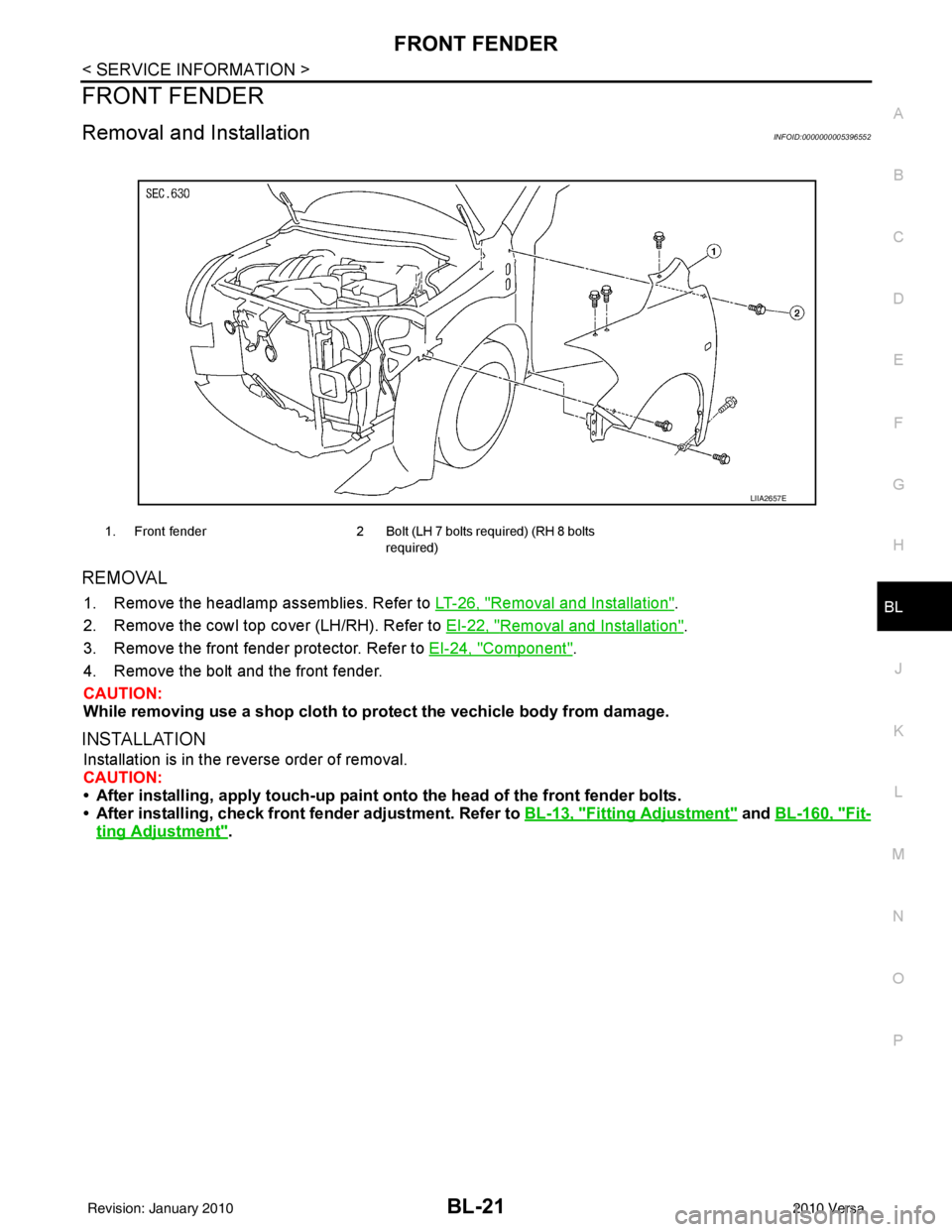
Removal and InstallationINFOID:0000000005396552
REMOVAL
1. Remove the headlamp assemblies. Refer to LT-26, "Removal and Installation".
2. Remove the cowl top cover (LH/RH). Refer to EI-22, "
Removal and Installation".
3. Remove the front fender protector. Refer to EI-24, "
Component".
4. Remove the bolt and the front fender.
CAUTION:
While removing use a shop cloth to pr otect the vechicle body from damage.
INSTALLATION
Installation is in the reverse order of removal.
CAUTION:
• After installing, apply touch-up paint on to the head of the front fender bolts.
• After installing, check front fender adjustment. Refer to BL-13, "
Fitting Adjustment" and BL-160, "Fit-
ting Adjustment".
1. Front fender 2 Bolt (LH 7 bolts required) (RH 8 bolts
required)
LIIA2657E
Revision: January 20102010 Versa
Page 3020 of 3745
HEADLAMP (FOR USA)LT-25
< SERVICE INFORMATION >
C
DE
F
G H
I
J
L
M A
B
LT
N
O P
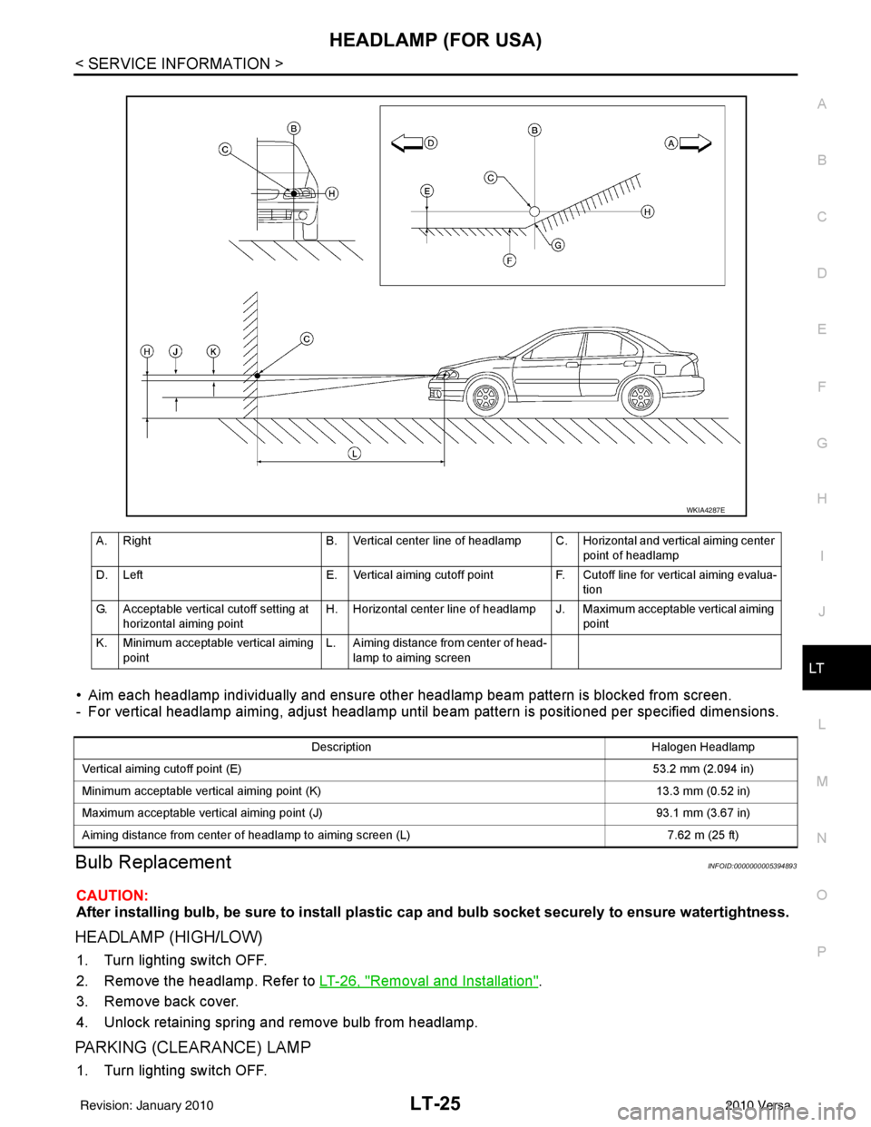
• Aim each headlamp individually and ensure other headlamp beam pattern is blocked from screen.
- For vertical headlamp aiming, adjust headlamp until beam pattern is positioned per specified dimensions.
Bulb ReplacementINFOID:0000000005394893
CAUTION:
After installing bulb, be sure to install plastic cap and bulb socket securely to ensure watertightness.
HEADLAMP (HIGH/LOW)
1. Turn lighting switch OFF.
2. Remove the headlamp. Refer to LT-26, "
Removal and Installation".
3. Remove back cover.
4. Unlock retaining spring and remove bulb from headlamp.
PARKING (CLEARANCE) LAMP
1. Turn lighting switch OFF.
A. Right B. Vertical center line of headlamp C. Horizontal and vertical aiming center
point of headlamp
D. Left E. Vertical aiming cutoff pointF. Cutoff line for vertical aiming evalua-
tion
G. Acceptable vertical cutoff setting at horizontal aiming point H. Horizontal center line of headlamp J. Maximum acceptable vertical aiming
point
K. Minimum acceptable vertical aiming point L. Aiming distance from center of head-
lamp to aiming screen
WKIA4287E
Description Halogen Headlamp
Vertical aiming cutoff point (E) 53.2 mm (2.094 in)
Minimum acceptable vertical aiming point (K) 13.3 mm (0.52 in)
Maximum acceptable vertical aiming point (J) 93.1 mm (3.67 in)
Aiming distance from center of headlamp to aiming screen (L) 7.62 m (25 ft)
Revision: January 20102010 Versa
Page 3021 of 3745
LT-26
< SERVICE INFORMATION >
HEADLAMP (FOR USA)
2. Remove the headlamp. Refer to LT-26, "Removal and Installation".
3. Turn bulb socket counterclockwise and unlock it.
4. Remove bulb from its socket.
FRONT TURN SIGNAL LAMP
1. Turn lighting switch OFF.
2. Remove the headlamp. Refer to LT-26, "
Removal and Installation".
3. Turn bulb socket counterclockwise and unlock it.
4. Remove bulb from its socket.
Removal and InstallationINFOID:0000000005394894
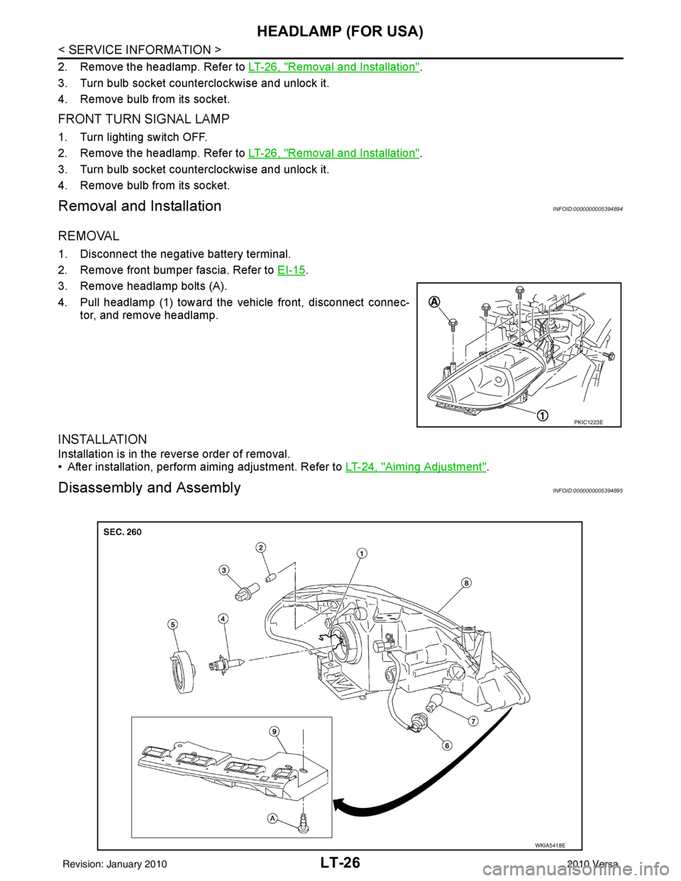
REMOVAL
1. Disconnect the negative battery terminal.
2. Remove front bumper fascia. Refer to EI-15
.
3. Remove headlamp bolts (A).
4. Pull headlamp (1) toward the vehicle front, disconnect connec- tor, and remove headlamp.
INSTALLATION
Installation is in the reverse order of removal.
• After installation, perform aiming adjustment. Refer to LT-24, "
Aiming Adjustment".
Disassembly and AssemblyINFOID:0000000005394895
PKIC1223E
WKIA5418E
Revision: January 20102010 Versa
Page 3034 of 3745
HEADLAMP (FOR CANADA) - DAYTIME LIGHT SYSTEM -
LT-39
< SERVICE INFORMATION >
C
D E
F
G H
I
J
L
M A
B
LT
N
O P
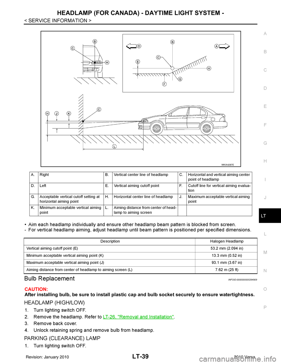
• Aim each headlamp individually and ensure other headlamp beam pattern is blocked from screen.
- For vertical headlamp aiming, adjust headlamp until beam pattern is positioned per specified dimensions.
Bulb ReplacementINFOID:0000000005394909
CAUTION:
After installing bulb, be sure to install plastic cap and bulb socket securely to ensure watertightness.
HEADLAMP (HIGH/LOW)
1. Turn lighting switch OFF.
2. Remove the headlamp. Refer to LT-26, "
Removal and Installation".
3. Remove back cover.
4. Unlock retaining spring and remove bulb from headlamp.
PARKING (CLEARANCE) LAMP
1. Turn lighting switch OFF.
A. Right B. Vertical center line of headlamp C. Horizontal and vertical aiming center
point of headlamp
D. Left E. Vertical aiming cutoff pointF. Cutoff line for vertical aiming evalua-
tion
G. Acceptable vertical cutoff setting at horizontal aiming point H. Horizontal center line of headlamp J. Maximum acceptable vertical aiming
point
K. Minimum acceptable vertical aiming point L. Aiming distance from center of head-
lamp to aiming screen
WKIA4287E
Description Halogen Headlamp
Vertical aiming cutoff point (E) 53.2 mm (2.094 in)
Minimum acceptable vertical aiming point (K) 13.3 mm (0.52 in)
Maximum acceptable vertical aiming point (J) 93.1 mm (3.67 in)
Aiming distance from center of headlamp to aiming screen (L) 7.62 m (25 ft)
Revision: January 20102010 Versa
Page 3035 of 3745
LT-40
< SERVICE INFORMATION >
HEADLAMP (FOR CANADA) - DAYTIME LIGHT SYSTEM -
2. Remove the headlamp. Refer to LT-26, "Removal and Installation".
3. Turn bulb socket counterclockwise and unlock it.
4. Remove bulb from its socket.
FRONT TURN SIGNAL LAMP
1. Turn lighting switch OFF.
2. Remove the headlamp. Refer to LT-26, "
Removal and Installation".
3. Turn bulb socket counterclockwise and unlock it.
4. Remove bulb from its socket.
Removal and InstallationINFOID:0000000005394910
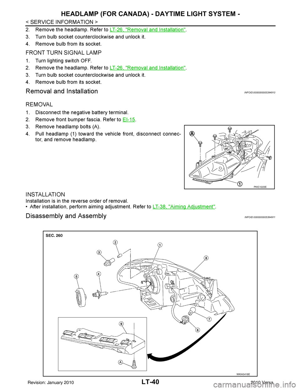
REMOVAL
1. Disconnect the negative battery terminal.
2. Remove front bumper fascia. Refer to EI-15
.
3. Remove headlamp bolts (A).
4. Pull headlamp (1) toward the vehicle front, disconnect connec- tor, and remove headlamp.
INSTALLATION
Installation is in the reverse order of removal.
• After installation, perform aiming adjustment. Refer to LT-38, "
Aiming Adjustment".
Disassembly and AssemblyINFOID:0000000005394911
PKIC1223E
WKIA5418E
Revision: January 20102010 Versa
Page 3057 of 3745
LT-62
< SERVICE INFORMATION >
TURN SIGNAL AND HAZARD WARNING LAMPS
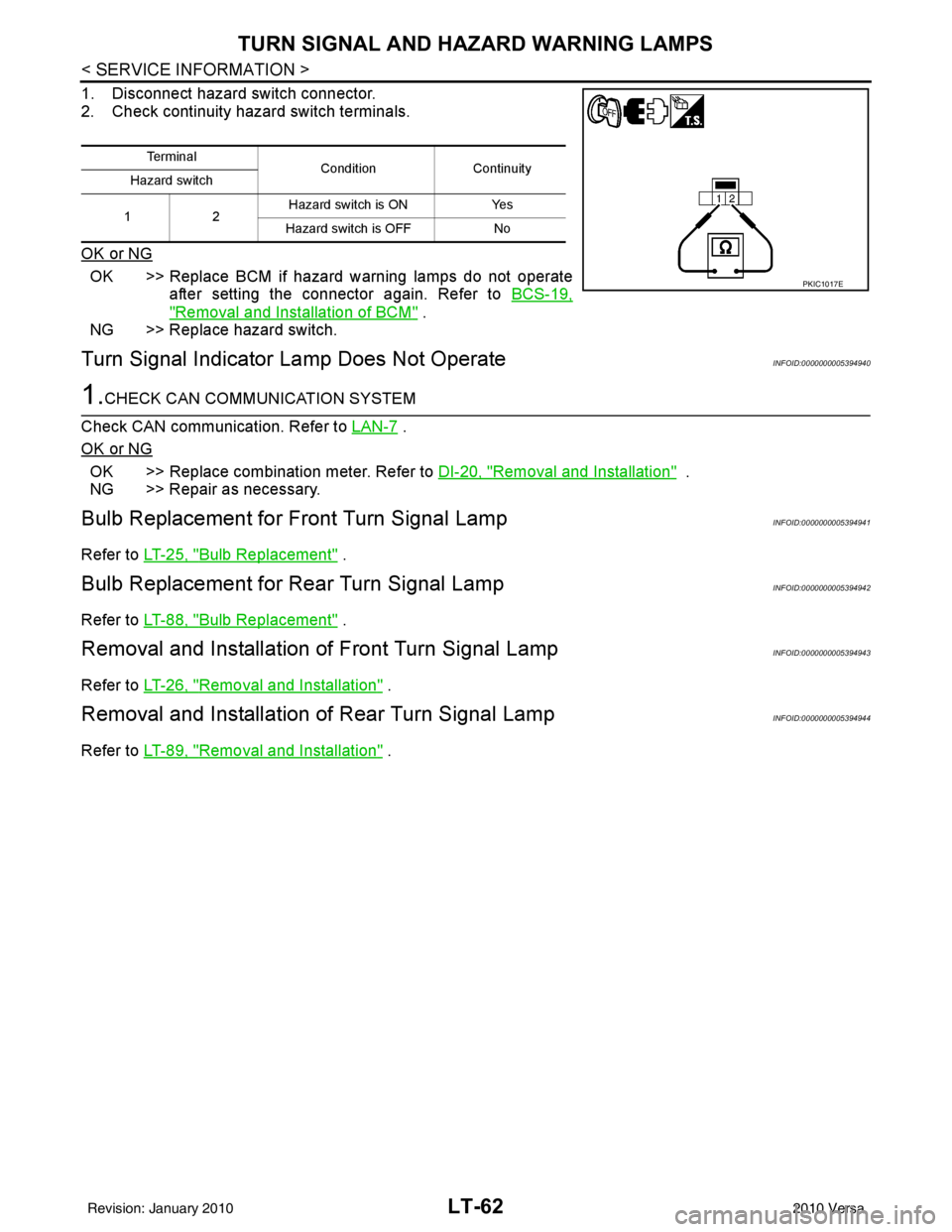
1. Disconnect hazard switch connector.
2. Check continuity hazard switch terminals.
OK or NG
OK >> Replace BCM if hazard warning lamps do not operateafter setting the connector again. Refer to BCS-19,
"Removal and Installation of BCM" .
NG >> Replace hazard switch.
Turn Signal Indicator Lamp Does Not OperateINFOID:0000000005394940
1.CHECK CAN COMMUNICATION SYSTEM
Check CAN communication. Refer to LAN-7
.
OK or NG
OK >> Replace combination meter. Refer to DI-20, "Removal and Installation" .
NG >> Repair as necessary.
Bulb Replacement for Front Turn Signal LampINFOID:0000000005394941
Refer to LT-25, "Bulb Replacement" .
Bulb Replacement for Rear Turn Signal LampINFOID:0000000005394942
Refer to LT-88, "Bulb Replacement" .
Removal and Installation of Front Turn Signal LampINFOID:0000000005394943
Refer to LT-26, "Removal and Installation" .
Removal and Installation of Rear Turn Signal LampINFOID:0000000005394944
Refer to LT-89, "Removal and Installation" .
Te r m i n a l
Condition Continuity
Hazard switch
12 Hazard switch is ON
Yes
Hazard switch is OFF No
PKIC1017E
Revision: January 20102010 Versa