Windows NISSAN TIIDA 2010 Service Repair Manual
[x] Cancel search | Manufacturer: NISSAN, Model Year: 2010, Model line: TIIDA, Model: NISSAN TIIDA 2010Pages: 3745, PDF Size: 73.67 MB
Page 496 of 3745
BCM (BODY CONTROL MODULE)BCS-7
< SERVICE INFORMATION >
C
DE
F
G H
I
J
L
M A
B
BCS
N
O P
• When CAN communication operation is detected, it switches to CAN communication status.
• When a state of the following switches changes , it switches to CAN communication state:
- Ignition switch
- Key switch (without Intelligent Key)
- Key switch and ignition knob switch (with Intelligent Key)
- Hazard switch
- Door lock/unlock switch (with power door locks)
- Front door switch (LH, RH)
- Rear door switch (LH, RH)
- Back door lock assembly (Hatchback)
- Trunk key cylinder switch (Sedan)
- Trunk lamp switch and trunk release solenoid (Sedan)
- Combination switch (passing, lighting switch 1st position, front fog lamp)
- Keyfob (lock/unlock signal) (with power door locks)
- Front door key cylinder switch LH
• When control performed only by BCM is required by switch, it shifts to CAN communication inactive mode.
• Status of combination switch reading function is changed.
SYSTEMS CONTROLLED BY BCM DIRECTLY
• Power door lock system (with power door locks). Refer to BL-23, "System Description" .
• Remote keyless entry system. Refer to BL-58, "
System Description" .
• Power window system (with power windows). Refer to GW-19, "
System Description" . NOTE
• Sunroof system (with sunroof). Refer to RF-11, "System Description". NOTE
• Room lamp timer. Refer to LT-94, "System Description" .
• Rear wiper and washer system (Hatchback). Refer to WW-26, "
System Description" .
NOTE:
Power supply only. No system control.
SYSTEMS CONTROLLED BY BCM AND IPDM E/R
• Panic system. Refer to BL-58, "System Description" .
• Vehicle security (theft warning) system. Refer to BL-219, "
System Description" .
• NVIS(NATS) system. Refer to BL-248, "
System Description" .
• Headlamp, tail lamp and battery saver control systems. Refer to LT-75, "
System Description", LT- 6 , "System
Description" or LT-28, "System Description" .
• Front fog lamp (with front fog lamps). Refer to LT-42, "
System Description" .
• Front wiper and washer system. Refer to WW-5, "
System Description" .
• Rear window defogger system. Refer to GW-51, "
System Description" .
SYSTEMS CONTROLLED BY BCM AND COMBINATION METER
• Warning chime. Refer to DI-43, "System Description" .
• Turn signal and hazard warning lamps. Refer to LT-51, "
System Description" .
SYSTEMS CONTROLLED BY BCM AND INTELLIGENT KEY UNIT (WITH INTELLIGENT KEY)
• Intelligent Key system. Refer to BL-88, "System Description" .
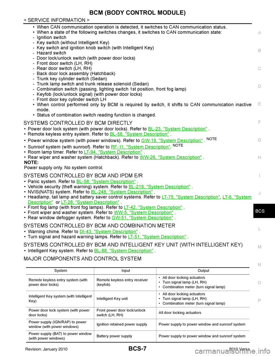
MAJOR COMPONENTS AND CONTROL SYSTEM
System Input Output
Remote keyless entry system (with
power door locks) Remote keyless entry receiver
(keyfob)• All door locking actuators
• Turn signal lamp (LH, RH)
• Combination meter (turn signal lamp)
Intelligent Key system (with Intelligent
Key) Intelligent Key unit• All door locking actuators
• Turn signal lamp (LH, RH)
• Combination meter (turn signal lamp)
Power door lock system (with power
door locks) Front power door lock/unlock
switch (LH, RH)
All door locking actuators
Power supply (IGN /RAP) to power
window (with power windows) Ignition retained power supply Power supply to power window and sunroof system
Power supply (BAT) to power window
(with power windows) Battery power supply
Power supply to power window and sunroof system
Revision: January 20102010 Versa
Page 505 of 3745
BCS-16
< SERVICE INFORMATION >
BCM (BODY CONTROL MODULE)
1: With Intelligent Key
2: Without Intelligent Key
3: Hatchback without Intelligent Key
4: Sedan without Intelligent Key
5: Hatchback
6: Sedan
7: With power door locks
8: With power windows
BCM Power Supply and Ground Circuit InspectionINFOID:0000000005395108
1.CHECK FUSES AND FUSIBLE LINK
• Check 40A fusible link (letter g , located in the fuse and fusible link box).
• Check 10A fuses [No. 6, 8 and 20, lo cated in the fuse block (J/B)].
OK or NG
OK >> GO TO 2.
NG >> If fuse is blown, be sure to eliminate cause of malfunction before installing new fuse. Refer to PG-
4, "Schematic" .
2.CHECK BCM POWER SUPPLY CIRCUIT
1. Turn ignition switch OFF.
2. Disconnect BCM.
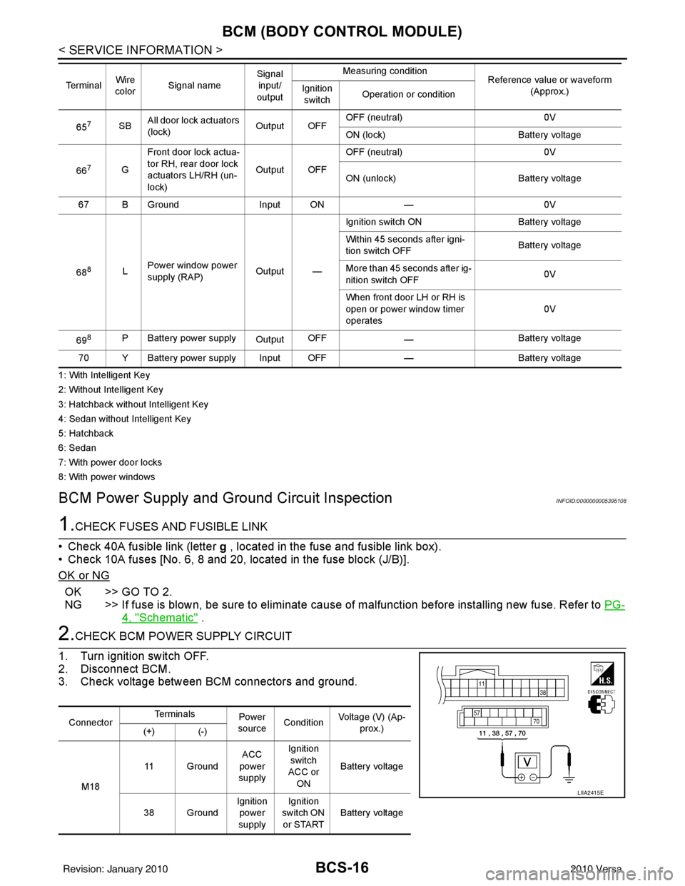
3. Check voltage between BCM connectors and ground.
657SB All door lock actuators
(lock) Output OFFOFF (neutral)
0V
ON (lock) Battery voltage
66
7G Front door lock actua-
tor RH, rear door lock
actuators LH/RH (un-
lock) Output OFFOFF (neutral)
0V
ON (unlock) Battery voltage
67 B Ground Input ON—0V
68
8L Power window power
supply (RAP)
Output —Ignition switch ON
Battery voltage
Within 45 seconds after igni-
tion switch OFF Battery voltage
More than 45 seconds after ig-
nition switch OFF 0V
When front door LH or RH is
open or power window timer
operates 0V
69
8P Battery power supply OutputOFF
— Battery voltage
70 Y Battery power supply Input OFF —Battery voltage
Te r m i n a l
Wire
color Signal name Signal
input/
output Measuring condition
Reference value or waveform
(Approx.)
Ignition
switch Operation or condition
Connector Te r m i n a l s
Power
source Condition Voltage (V) (Ap-
prox.)
(+) (-)
M18 11 Ground
ACC
power
supply Ignition
switch
ACC or
ON Battery voltage
38 Ground Ignition
power
supply Ignition
switch ON or START Battery voltage
LIIA2415E
Revision: January 20102010 Versa
Page 511 of 3745

BL-2
Keyfob Function (Unlock) Check ............................82
ID Code Entry Procedure .................................... ...82
Keyfob Battery Replacement ............................... ...85
Removal and Installation of Remote Keyless Entry
Receiver .............................................................. ...
85
INTELLIGENT KEY SYSTEM ............................86
Component Parts and Harness Connector Loca-
tion ....................................................................... ...
86
System Description .................................................88
CAN Communication System Description ..............95
Schematic ............................................................ ...96
Wiring Diagram - I/KEY - ..................................... ...98
Intelligent Key Unit Har ness Connector Terminal
Layout .................................................................. ..
108
Terminal and Reference Value for Intelligent Key
Unit ........................................................................
108
Steering Lock Solenoid Harness Connector Ter-
minal Layout ..........................................................
110
Terminal and Reference Value for Steering Lock
Solenoid .................................................................
110
Terminal and Reference Value for BCM ................111
Trouble Diagnosis Procedure ................................115
CONSULT-III Functions (INTELLIGENT KEY) ......117
CONSULT-III Application Item ............................. ..117
Trouble Diagnosis Symptom Chart ........................119
CAN Communication System Inspection ...............126
Power Supply and Ground Circuit Inspection ........126
Key Switch (Intelligent Key Unit Input) Check .......127
Key Switch (BCM Input) Check .............................128
Ignition Knob Switch Check ................................. ..129
Door Switch Check (Hatchback) ............................131
Door Switch Check (Sedan) ..................................133
Door Request Switch Check ..................................135
Back Door Request Switch Check (Hatchback) ....137
Trunk Opener Request Switch Check (Sedan) ... ..138
Unlock Sensor Check ............................................140
Intelligent Key Warning Buzzer(s) Check ..............142
Outside Key Antenna (Dri ver Side and Passenger
Side) Check ......................................................... ..
143
Outside Key Antenna (Rear Bumper) Check .........144
Inside Key Antenna Check ....................................146
Steering Lock Solenoid Check ............................ ..147
Key Interlock Solenoid (With M/T) Check ..............149
Ignition Switch Position Check ............................ ..150
Stop Lamp Switch Check (With CVT or A/T) ....... ..150
Stop Lamp Switch Check (With M/T) .....................152
CVT or A/T Shift Selector (Park Position Switch)
Check .................................................................. ..
153
"P-SHIFT" Warning Lamp (With CVT or A/T)
Check ....................................................................
154
"LOCK" Warning Lamp (With M/T) Check .............155
"KEY" Warning Lamp (RED) Check ......................155
"KEY" Warning Lamp (G REEN) Check .................155
Check Warning Chime in Combination Meter ........156
Hazard Function Check .........................................156
Horn Function Check .... .........................................157
Headlamp Function Chec k ....................................157
Intelligent Key Battery Replacement ................... ..158
Remote Keyless Entry Function ............................158
Removal and Installation of Intelligent Key Unit ... .158
DOOR ...............................................................160
Fitting Adjustment ................................................ .160
Removal and Installation .......................................163
FRONT DOOR LOCK ..................................... ..166
Component Parts Location .................................. .166
Removal and Installation .......................................166
REAR DOOR LOCK ....................................... ..169
Component Parts Location .................................. .169
Removal and Installation .......................................169
BACK DOOR LOCK ....................................... ..172
Component Parts and Harness Connector Loca-
tion ....................................................................... .
172
System Description ...............................................172
Wiring Diagram - B/DOOR - ..................................173
Terminal and Reference Value for BCM ...............175
Terminal and Reference Value for Intelligent Key
Unit ....................................................................... .
179
CONSULT-III Function (BCM) ..............................181
Work Flow .............................................................182
Trouble Diagnosis Chart by Symptom ..................182
BCM Power Supply and Ground Circuit Inspection
.
182
Check Back Door Opener Switch Circuit (Without
Intelligent Key or Power Windows) ...................... .
183
Check Back Door Opener Switch Circuit (Without
Intelligent Key, with Power Windows) .................. .
186
Check Back Door Opener Switch Circuit (With In-
telligent Key) ........................................................ .
188
Check Back Door Lock Assembly (Actuator) Cir-
cuit ........................................................................
190
Removal and Installation .......................................192
TRUNK LID ..................................................... ..193
Fitting Adjustment ................................................ .193
Trunk Lid Assembly ..............................................193
Trunk Lid Lock ......................................................194
Trunk Lid Striker ....................................................194
Trunk Lid Stay Disposal ........................................195
TRUNK LID OPENER .......................................196
Component Parts and Harness Connector Loca-
tion ....................................................................... .
196
System Description ...............................................196
Wiring Diagram - TLID - ........................................197
Terminal and Reference Value for BCM ...............199
Terminal and Reference Value for Intelligent Key
Unit ....................................................................... .
203
CONSULT-III Function (BCM) ..............................205
Work Flow .............................................................206
Trouble Diagnosis Chart by Symptom ..................206
BCM Power Supply and Ground Circuit Inspection
.
206
Check Trunk Lid Opener Switch Circuit (Without
Intelligent Key or Power Windows) ...................... .
207
Revision: January 20102010 Versa
Page 512 of 3745

BL-3
C
DE
F
G H
J
K L
M A
B
BL
N
O P
Check Trunk Lid Opener S
witch Circuit (Without
Intelligent Key, with Power Windows) ................. ..
210
Check Trunk Lid Opener Switch Circuit (With Intel-
ligent Key) ........................................................... ..
212
Check Trunk Release Solenoid Circuit .................214
FUEL FILLER LID OPENER ............................217
Removal and Installation of Fuel Filler Lid Opener ..217
VEHICLE SECURITY (THEFT WARNING)
SYSTEM ...........................................................
218
Component Parts and Harness Connector Loca-
tion ...................................................................... ..
218
System Description ...............................................219
CAN Communication System Description .............221
Schematic .............................................................222
Wiring Diagram - VEHSEC - .................................223
Terminal and Reference Value for BCM ...............227
Terminal and Reference Value for Intelligent Key
Unit ...................................................................... ..
231
CONSULT-III Function (BCM) ...............................233
Trouble Diagnosis .................................................235
Preliminary Check .................................................235
Symptom Chart .....................................................237
Diagnosis Procedure 1 ..........................................238
Diagnosis Procedure 2 ..........................................241
Diagnosis Procedure 3 ..........................................242
Diagnosis Procedure 4 ..........................................242
Diagnosis Procedure 5 ..........................................242
Diagnosis Procedure 6 ..........................................242
Diagnosis Procedure 7 ..........................................242
Diagnosis Procedure 8 ..........................................244
Diagnosis Procedure 9 ........................................ ..245
NATS (Nissan Anti-Theft System) ................248
Component Parts and Harness Connector Loca-
tion .........................................................................
248
System Description ................................................248
System Composition ..............................................249
ECM Re-communicating Function .........................249
Wiring Diagram - NATS - .......................................251
Terminal and Reference Value for BCM ................252
CONSULT-III Function ........................................ ..256
Trouble Diagnosis Procedure ................................257
Trouble Diagnosis ..................................................259
Diagnosis Procedure 1 ..........................................260
Diagnosis Procedure 2 ..........................................262
Diagnosis Procedure 3 ..........................................263
Diagnosis Procedure 4 ..........................................264
Diagnosis Procedure 5 ..........................................265
Diagnosis Procedure 6 ..........................................266
How to Replace NATS Antenna Amp ....................266
BODY REPAIR ................................................267
Body Exterior Paint Color ......................................267
Body Component Parts .........................................269
Corrosion Protection ..............................................274
Body Sealing .........................................................278
Body Construction .................................................284
Body Alignment .....................................................286
Handling Precaution for Plastics ............................303
Precaution in Repairing High Strength Steel .........307
Foam Repair ..........................................................310
Replacement Operation .........................................313
Revision: January 20102010 Versa
Page 550 of 3745

POWER DOOR LOCK SYSTEMBL-41
< SERVICE INFORMATION >
C
DE
F
G H
J
K L
M A
B
BL
N
O P
1: With Intelligent Key
2: Without Intelligent Key
3: Hatchback without Intelligent Key
4: Sedan without Intelligent Key
5: Hatchback
6: Sedan
7: With power door locks
8: With power windows
Work FlowINFOID:0000000005396561
1. Check the symptom and customer's requests.
2. Understand the outline of system. Refer to BL-23, "
System Description" .
3. According to the trouble diagnosis chart, repair or replace the cause of the malfunction. Refer to BL-119,
"Trouble Diagnosis Symptom Chart" .
4. Does power door lock system operate normally? OK: GO TO 5, NG: GO TO 3.
5. Inspection End.
CONSULT-III Function (BCM)INFOID:0000000005396562
CONSULT-III can display each diagnostic item using the diagnostic test modes shown following.
WORK SUPPORT
657SB All door lock actuators
(lock) Output OFFOFF (neutral)
0V
ON (lock) Battery voltage
66
7G Front door lock actua-
tor RH, rear door lock
actuators LH/RH (un-
lock) Output OFFOFF (neutral)
0V
ON (unlock) Battery voltage
67 B Ground Input ON—0V
68
8L Power window power
supply (RAP)
Output —Ignition switch ON
Battery voltage
Within 45 seconds after igni-
tion switch OFF Battery voltage
More than 45 seconds after ig-
nition switch OFF 0V
When front door LH or RH is
open or power window timer
operates 0V
69
8P Battery power supply OutputOFF
— Battery voltage
70 Y Battery power supply Input OFF —Battery voltage
Te r m i n a l
Wire
color Signal name Signal
input/
output Measuring condition
Reference value or waveform
(Approx.)
Ignition
switch Operation or condition
Diagnostic mode
Description
WORK SUPPORT Supports inspections and adjustments. Commands are transmitted to the BCM for setting the status
suitable for required operation, input/output signals are received from the BCM and received date
is displayed.
DATA MONITOR Displays BCM input/output data in real time. ACTIVE TEST Operation of electrical loads can be checked by sending drive signal to them.
SELF DIAGNOSTIC RESULT Displays BCM self-diagnosis results.
CAN DIAG SUPPORT MNTR The result of transmit/receive diagnosis of CAN communication can be read. ECU IDENTIFICATION BCM part number can be read.CONFIGURATION Performs BCM configuration read/write functions.
Revision: January 20102010 Versa
Page 578 of 3745
REMOTE KEYLESS ENTRY SYSTEMBL-69
< SERVICE INFORMATION >
C
DE
F
G H
J
K L
M A
B
BL
N
O P
1: With Intelligent Key
2: Without Intelligent Key
3: Hatchback without Intelligent Key
4: Sedan without Intelligent Key
5: Hatchback
6: Sedan
7: With power door locks
8: With power windows
How to Perform Trouble DiagnosisINFOID:0000000005396579
1. Confirm the symptom or customer complaint.
2. Understand operation, description and function description. Refer to BL-58, "
System Description" .
3. Perform the Preliminary Check. Refer to LT-13, "
Preliminary Check" .
4. Check symptom and repair or replace the component.
5. Does the remote keyless entry system operate normally? If YES, GO TO 6. If NO, GO TO 4.
6. Inspection End.
Preliminary CheckINFOID:0000000005396580
CHECK BCM CONFIGURATION
1.CHECK BCM CONFIGURATION
Confirm BCM configuration for "KEYLESS ENTRY" is set to "WITH". Refer to BCS-19, "
Configuration" .
OK or NG
OK >> Refer to BL-71, "Work Flow" .
NG >> Change BCM configuration for "KEYLESS ENTRY" to "WITH". Refer to BCS-19, "
Configuration" .
CONSULT-III Function (BCM)INFOID:0000000005396581
CONSULT-III can display each diagnostic item using the diagnostic test modes shown following.
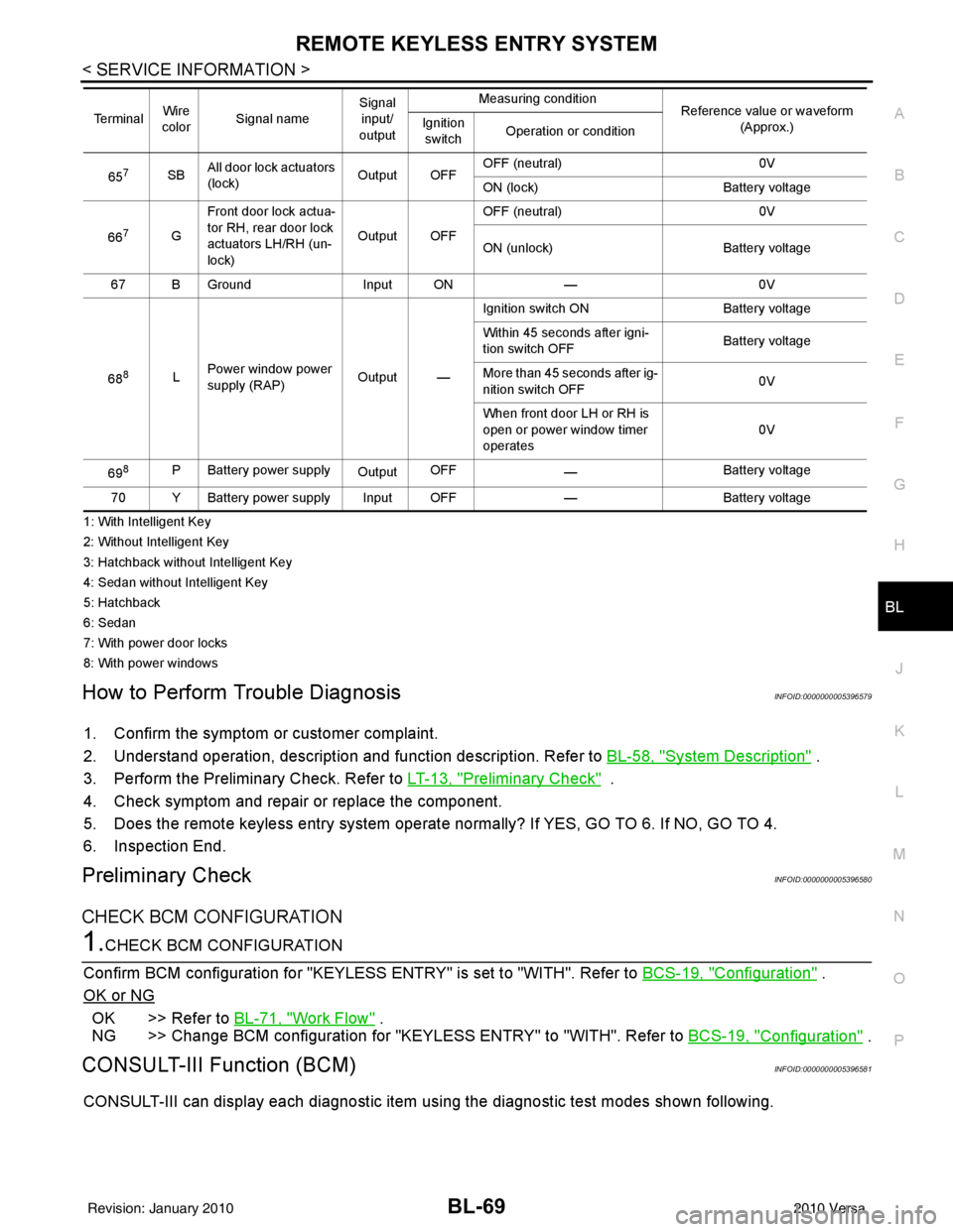
657SBAll door lock actuators
(lock) Output OFFOFF (neutral)
0V
ON (lock) Battery voltage
66
7G Front door lock actua-
tor RH, rear door lock
actuators LH/RH (un-
lock) Output OFFOFF (neutral)
0V
ON (unlock) Battery voltage
67 B Ground Input ON—0V
68
8L Power window power
supply (RAP)
Output —Ignition switch ON
Battery voltage
Within 45 seconds after igni-
tion switch OFF Battery voltage
More than 45 seconds after ig-
nition switch OFF 0V
When front door LH or RH is
open or power window timer
operates 0V
69
8P Battery power supply OutputOFF
— Battery voltage
70 Y Battery power supply Input OFF —Battery voltage
Te r m i n a l
Wire
color Signal name Signal
input/
output Measuring condition
Reference value or waveform
(Approx.)
Ignition
switch Operation or condition
Revision: January 20102010 Versa
Page 624 of 3745
INTELLIGENT KEY SYSTEMBL-115
< SERVICE INFORMATION >
C
DE
F
G H
J
K L
M A
B
BL
N
O P
1: With Intelligent Key
2: Without Intelligent Key
3: Hatchback without Intelligent Key
4: Sedan without Intelligent Key
5: Hatchback
6: Sedan
7: With power door locks
8: With power windows
Trouble Diagnosis ProcedureINFOID:0000000005396608
PRELIMINARY CHECK
1.GET SYMPTOMS
Listen to customer c oncerns. (Get symptoms)
NOTE:
If customer reports a “No start” condition, request all Intelligent Keys to be brought to the dealer in case of
Intelligent Key system malfunction.
Intelligent Key or mechanical key service request>>For further information, refer to CONSULT-III operation
manual.
Malfunctions>>GO TO 2
2.CHECK BCM CONFIGURATION
Confirm BCM configuration for "I- KEY" is set to "WITH". Refer to BCS-19, "
Configuration".
OK or NG
OK >> GO TO 3
NG >> Change BCM configuration for "I-KEY" to "WITH". Refer to BCS-19, "
Configuration".
3.START ENGINE WITH INTELLIGENT KEY
Check if the engine could be started by all registered Intelligent Keys.
The engine cannot be started by some Intelligent Keys>>Int elligent Key is low battery or malfunction. Refer
to BL-158, "
Intelligent Key Battery Replacement".
The engine cannot be started by all Intelligent Keys >> GO TO 4
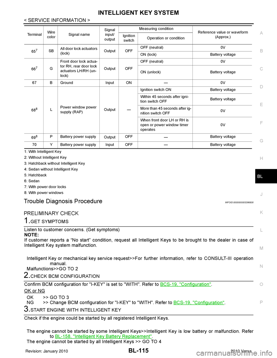
657SB All door lock actuators
(lock) Output OFFOFF (neutral)
0V
ON (lock) Battery voltage
66
7G Front door lock actua-
tor RH, rear door lock
actuators LH/RH (un-
lock) Output OFFOFF (neutral)
0V
ON (unlock) Battery voltage
67 B Ground Input ON—0V
68
8L Power window power
supply (RAP)
Output —Ignition switch ON
Battery voltage
Within 45 seconds after igni-
tion switch OFF Battery voltage
More than 45 seconds after ig-
nition switch OFF 0V
When front door LH or RH is
open or power window timer
operates 0V
69
8P Battery power supply OutputOFF
— Battery voltage
70 Y Battery power supply Input OFF —Battery voltage
Te r m i n a l
Wire
color Signal name Signal
input/
output Measuring condition
Reference value or waveform
(Approx.)
Ignition
switch Operation or condition
Revision: January 20102010 Versa
Page 681 of 3745
BL-172
< SERVICE INFORMATION >
BACK DOOR LOCK
BACK DOOR LOCK
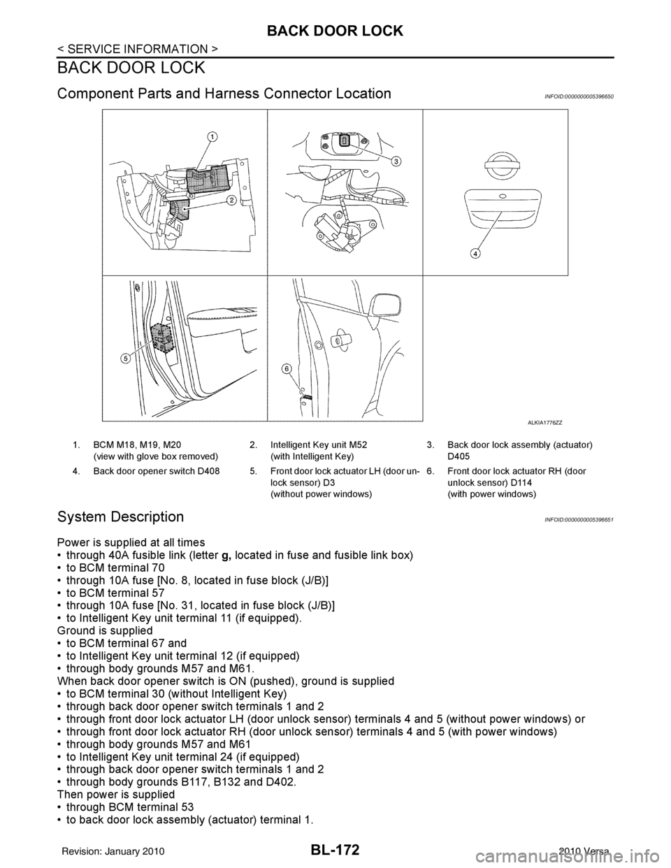
Component Parts and Harness Connector LocationINFOID:0000000005396650
System DescriptionINFOID:0000000005396651
Power is supplied at all times
• through 40A fusible link (letter g, located in fuse and fusible link box)
• to BCM terminal 70
• through 10A fuse [No. 8, located in fuse block (J/B)]
• to BCM terminal 57
• through 10A fuse [No. 31, located in fuse block (J/B)]
• to Intelligent Key unit terminal 11 (if equipped).
Ground is supplied
• to BCM terminal 67 and
• to Intelligent Key unit terminal 12 (if equipped)
• through body grounds M57 and M61.
When back door opener switch is ON (pushed), ground is supplied
• to BCM terminal 30 (without Intelligent Key)
• through back door opener switch terminals 1 and 2
• through front door lock actuator LH (door unlock s ensor) terminals 4 and 5 (without power windows) or
• through front door lock actuator RH (door unlock sensor) terminals 4 and 5 (with power windows)
• through body grounds M57 and M61
• to Intelligent Key unit terminal 24 (if equipped)
• through back door opener switch terminals 1 and 2
• through body grounds B117, B132 and D402.
Then power is supplied
• through BCM terminal 53
• to back door lock assembly (actuator) terminal 1.
ALKIA1776ZZ
1. BCM M18, M19, M20
(view with glove box removed) 2. Intelligent Key unit M52
(with Intelligent Key) 3. Back door lock assembly (actuator)
D405
4. Back door opener switch D408 5. Front door lock actuator LH (door un- lock sensor) D3
(without power windows)6. Front door lock actuator RH (door
unlock sensor) D114
(with power windows)
Revision: January 20102010 Versa
Page 688 of 3745

BACK DOOR LOCKBL-179
< SERVICE INFORMATION >
C
DE
F
G H
J
K L
M A
B
BL
N
O P
1: With Intelligent Key
2: Without Intelligent Key
3: Hatchback without Intelligent Key
4: Sedan without Intelligent Key
5: Hatchback
6: Sedan
7: With power door locks
8: With power windows
Terminal and Reference Valu e for Intelligent Key UnitINFOID:0000000005612424
657SBAll door lock actuators
(lock) Output OFFOFF (neutral)
0V
ON (lock) Battery voltage
66
7G Front door lock actua-
tor RH, rear door lock
actuators LH/RH (un-
lock) Output OFFOFF (neutral)
0V
ON (unlock) Battery voltage
67 B Ground Input ON—0V
68
8L Power window power
supply (RAP)
Output —Ignition switch ON
Battery voltage
Within 45 seconds after igni-
tion switch OFF Battery voltage
More than 45 seconds after ig-
nition switch OFF 0V
When front door LH or RH is
open or power window timer
operates 0V
69
8P Battery power supply OutputOFF
— Battery voltage
70 Y Battery power supply Input OFF —Battery voltage
Te r m i n a l
Wire
color Signal name Signal
input/
output Measuring condition
Reference value or waveform
(Approx.)
Ignition
switch Operation or condition
TerminalWire
Color Item Condition
Voltage (V)Approx.
Ignition
Switch
Position Operation or Conditions
1R Steering lock solenoid
power supply
LOCK
— 5
2 L CAN-H —— —
3 P CAN-L —— —
4O Intelligent Key warning
buzzer LOCKOperate door request
switch. Buzzer OFF
Battery voltage
Sound buzzer 0
5G Front door request
switch LH —Press door request switch (driver side).
0
Other than above 5
6 Y Ignition switch (ON) ON —Battery voltage
7 LG Key switch LOCKInsert mechanical key into ignition switch. Battery voltage
Remove mechanical key from ignition
switch.
0
10
*1W CVT or A/T shift selec-
tor (park position
switch) ON
Shift lever in park position.
0
Other than above Battery voltage
11 SB Power source (Fus e) — —Battery voltage
Revision: January 20102010 Versa
Page 691 of 3745
BL-182
< SERVICE INFORMATION >
BACK DOOR LOCK
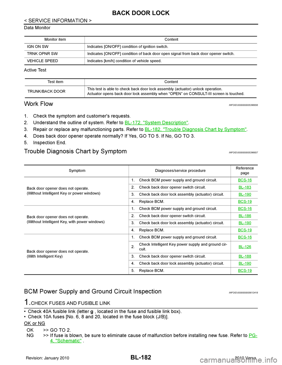
Data Monitor
Active Test
Work FlowINFOID:0000000005396656
1. Check the symptom and customer's requests.
2. Understand the outline of system. Refer to BL-172, "
System Description".
3. Repair or replace any malfunctioning parts. Refer to BL-182, "
Trouble Diagnosis Chart by Symptom".
4. Does back door opener operate normally? If Yes, GO TO 5. If No, GO TO 3.
5. Inspection End.
Trouble Diagnosis Chart by SymptomINFOID:0000000005396657
BCM Power Supply and Ground Circuit InspectionINFOID:0000000005612418
1.CHECK FUSES AND FUSIBLE LINK
• Check 40A fusible link (letter g , located in the fuse and fusible link box).
• Check 10A fuses [No. 6, 8 and 20, lo cated in the fuse block (J/B)].
OK or NG
OK >> GO TO 2.
NG >> If fuse is blown, be sure to eliminate cause of malfunction before installing new fuse. Refer to PG-
4, "Schematic" .
Monitor itemContent
IGN ON SW Indicates [ON/OFF] condition of ignition switch.
TRNK OPNR SW Indicates [ON/OFF] condition of back door open signal from back door opener switch.
VEHICLE SPEED Indicates [km/h] condition of vehicle speed.
Test item Content
TRUNK/BACK DOOR This test is able to check back door lock assembly (actuator) unlock operation.
Actuator opens back door lock assembly when “OPEN” on CONSULT-III screen is touched.
Symptom
Diagnoses/service procedureReference
page
Back door opener does not operate.
(Without Intelligent Key or power windows) 1. Check BCM power supply and ground circuit.
BCS-16
2. Check back door opener switch circuit. BL-183
3. Check back door lock assembly (actuator) circuit.BL-190
4. Replace BCM.BCS-19
Back door opener does not operate.
(Without Intelligent Key, with power windows)1. Check BCM power supply and ground circuit.
BCS-162. Check back door opener switch circuit. BL-186
3. Check back door lock assembly (actuator) circuit.BL-190
4. Replace BCM.BCS-19
Back door opener does not operate.
(With Intelligent Key)1. Check BCM power supply and ground circuit.
BCS-16
2.Check Intelligent Key power supply and ground cir-
cuit. BL-126
3. Check back door opener switch circuit.
BL-188
4. Check back door lock assembly (actuator) circuit.BL-190
5. Replace BCM.BCS-19
Revision: January 20102010 Versa