model variation NISSAN TIIDA 2010 Service Repair Manual
[x] Cancel search | Manufacturer: NISSAN, Model Year: 2010, Model line: TIIDA, Model: NISSAN TIIDA 2010Pages: 3745, PDF Size: 73.67 MB
Page 508 of 3745
BCM (BODY CONTROL MODULE)BCS-19
< SERVICE INFORMATION >
C
DE
F
G H
I
J
L
M A
B
BCS
N
O P
Contents displayed
No malfunction>>Inspection End
Malfunction in CAN communication system>>After printing the monitor items, go to “CAN System”. Refer to
LAN-17, "
Trouble Diagnosis Flow Chart".
ConfigurationINFOID:0000000005395111
DESCRIPTION
CONFIGURATION has three functions as follows:
• READ CONFIGURATION is the function to read (e xtract) vehicle configuration of current BCM.
• WRITE CONFIGURATION-Manual selection is the functi on to select and write vehicle configuration on BCM
manually.
• WRITE CONFIGURATION-Config file is the function to write vehicle configuration with the data extracted
from current BCM.
• For READ CONFIGURATION and WRITE CONFIGURATION -Config file, refer to CONSULT-III Operation
Manual.
• For WRITE CONFIGURATION-Manual selection using the following flow chart, identify the correct model
and configuration list. Confirm and/or change setting val ue for each item according to the configuration list.
Depending on CONSULT-III software version being used, some or all of the write configuration items shown
in the following configuration lists may be display ed. If an item does not appear on the CONSULT-III WRITE
CONFIGURATION-Manual selection screen(s), then it is an auto setting item and it cannot be manually set
or changed.
NOTE:
Confirm vehicle model on IDENTIFICATION PLATE. Refer to GI-43, "
Model Variation".
CAUTION:
• When replacing BCM, you must perform WRITE CONFIGURATION with CONSULT-III.
• Complete the procedure of WRITE CONFIGURATION in order.
• If you set incorrect WRITE CONF IGURATION, incidents will occur.
• Configuration is different for each vehicle model. Confirm conf iguration of each vehicle model.
Removal and Installation of BCMINFOID:0000000005395112
REMOVAL
CAUTION:
Before replacing BCM, perform “READ CONFIGURATI ON" to save or print current vehicle specifica-
tion. Refer to BCS-19, "
Configuration".
1. Disconnect the battery negative terminal.
2. Remove the glove box. Refer to IP-12, "
Removal and Installation".
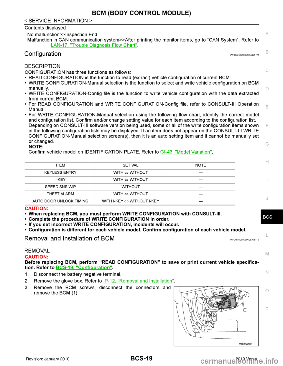
3. Remove the BCM screws, disconnect the connectors and remove the BCM (1).
ITEM SET VAL NOTE
KEYLESS ENTRY WITH ⇔ WITHOUT —
I-KEY WITH ⇔ WITHOUT —
SPEED SNS WIP WITHOUT —
THEFT ALARM WITH ⇔ WITHOUT —
AUTO DOOR UNLOCK TIMING WITH I-KEY ⇔ WITHOUT I-KEY —
WKIA5672E
Revision: January 20102010 Versa
Page 1290 of 3745
![NISSAN TIIDA 2010 Service Repair Manual INSPECTION AND ADJUSTMENTEC-25
< BASIC INSPECTION > [HR16DE]
C
D
E
F
G H
I
J
K L
M A
EC
NP
O
VIN REGISTRATION : Special Repair RequirementINFOID:0000000005398239
1.CHECK VIN
Check the VIN of the vehic](/img/5/57397/w960_57397-1289.png "NISSAN TIIDA 2010 Service Repair Manual INSPECTION AND ADJUSTMENTEC-25
< BASIC INSPECTION > [HR16DE]
C
D
E
F
G H
I
J
K L
M A
EC
NP
O
VIN REGISTRATION : Special Repair RequirementINFOID:0000000005398239
1.CHECK VIN
Check the VIN of the vehic")
INSPECTION AND ADJUSTMENTEC-25
< BASIC INSPECTION > [HR16DE]
C
D
E
F
G H
I
J
K L
M A
EC
NP
O
VIN REGISTRATION : Special Repair RequirementINFOID:0000000005398239
1.CHECK VIN
Check the VIN of the vehicle and note it. Refer to GI-43, "
Model Variation".
>> GO TO 2.
2.PERFORM VIN REGISTRATION
With CONSULT-III
1. Turn ignition switch ON and engine stopped.
2. Select “VIN REGISTRATION” in “WORK SUPPORT” mode.
3. Follow the instruction of CONSULT-III display.
>> END
ACCELERATOR PEDAL RELEAS ED POSITION LEARNING
ACCELERATOR PEDAL RELEASED PO SITION LEARNING : DescriptionINFOID:0000000005398240
Accelerator Pedal Released Position Learning is a function of ECM to learn the fully released position of the
accelerator pedal by monitoring the accelerator pedal pos ition sensor output signal. It must be performed each
time harness connector of accelerator pedal position sensor or ECM is disconnected.
ACCELERATOR PEDAL RELEASED POSITION LEARNING : Special Repair Re-
quirement
INFOID:0000000005398241
1.START
1. Make sure that accelerator pedal is fully released.
2. Turn ignition switch ON and wait at least 2 seconds.
3. Turn ignition switch OFF and wait at least 10 seconds.
4. Turn ignition switch ON and wait at least 2 seconds.
5. Turn ignition switch OFF and wait at least 10 seconds.
>> END
THROTTLE VALVE CLOSED POSITION LEARNING
THROTTLE VALVE CLOSED POSITION LEARNING : DescriptionINFOID:0000000005398242
Throttle Valve Closed Position Learning is a function of ECM to learn the fully closed position of the throttle
valve by monitoring the throttle position sensor out put signal. It must be performed each time harness connec-
tor of electric throttle contro l actuator or ECM is disconnected.
THROTTLE VALVE CLOSED POSITION LEA RNING : Special Repair Requirement
INFOID:0000000005398243
1.START
1. Make sure that accelerator pedal is fully released.
2. Turn ignition switch ON.
3. Turn ignition switch OFF and wait at least 10 seconds. Make sure that throttle valve moves during above 10 seconds by confirming the operating sound.
>> END
IDLE AIR VOLUME LEARNING
IDLE AIR VOLUME LEARNING : DescriptionINFOID:0000000005398244
Idle Air Volume Learning is a function of ECM to lear n the idle air volume that keeps each engine idle speed
within the specific range. It must be performed under any of the following conditions:
Revision: January 20102010 Versa
Page 1845 of 3745
![NISSAN TIIDA 2010 Service Repair Manual EC-580
< SERVICE INFORMATION >[MR18DE]
BASIC SERVICE PROCEDURE
5. Perform
EC-580, "Idle Air Volume Learning".
VIN RegistrationINFOID:0000000005532407
DESCRIPTION
VIN Registration is an operation to r](/img/5/57397/w960_57397-1844.png "NISSAN TIIDA 2010 Service Repair Manual EC-580
< SERVICE INFORMATION >[MR18DE]
BASIC SERVICE PROCEDURE
5. Perform
EC-580, \"Idle Air Volume Learning\".
VIN RegistrationINFOID:0000000005532407
DESCRIPTION
VIN Registration is an operation to r")
EC-580
< SERVICE INFORMATION >[MR18DE]
BASIC SERVICE PROCEDURE
5. Perform
EC-580, "Idle Air Volume Learning".
VIN RegistrationINFOID:0000000005532407
DESCRIPTION
VIN Registration is an operation to registering VIN in ECM. It must be performed each time ECM is replaced.
NOTE:
Accurate VIN which is registered in ECM ma y be required for Inspection & Maintenance (I/M).
OPERATION PROCEDURE
With CONSULT-III
1. Check the VIN of the vehicle and note it. Refer to GI-43, "Model Variation".
2. Turn ignition switch ON and engine stopped.
3. Select “VIN REGISTRATION ” in “WORK SUPPORT” mode.
4. Follow the instruction of CONSULT-III display.
Accelerator Pedal Released Position LearningINFOID:0000000005532408
DESCRIPTION
Accelerator Pedal Released Position Learning is an operation to learn the fully released position of the accel-
erator pedal by monitoring the accelerator pedal positi on sensor output signal. It must be performed each time
harness connector of accelerator pedal pos ition sensor or ECM is disconnected.
OPERATION PROCEDURE
1. Make sure that accelerator pedal is fully released.
2. Turn ignition switch ON and wait at least 2 seconds.
3. Turn ignition switch OFF and wait at least 10 seconds.
4. Turn ignition switch ON and wait at least 2 seconds.
5. Turn ignition switch OFF and wait at least 10 seconds.
Throttle Valve Closed Position LearningINFOID:0000000005532409
DESCRIPTION
Throttle Valve Closed Position Learning is an operation to l earn the fully closed position of the throttle valve by
monitoring the throttle position sensor output signal . It must be performed each time harness connector of
electric throttle control actuator or ECM is disconnected.
OPERATION PROCEDURE
1. Make sure that accelerator pedal is fully released.
2. Turn ignition switch ON.
3. Turn ignition switch OFF and wait at least 10 seconds. Make sure that throttle valve moves during above 10 seconds by confirming the operating sound.
Idle Air Volume LearningINFOID:0000000005532410
DESCRIPTION
Idle Air Volume Learning is an operation to learn the idle air volume that keeps each engine within the specific
range. It must be performed under any of the following conditions:
• Each time electric throttle control actuator or ECM is replaced.
• Idle speed or ignition timing is out of specification.
PREPARATION
Before performing Idle Air Volume Learning, make sure that all of the following conditions are satisfied.
Learning will be cancelled if any of the follo wing conditions are missed for even a moment.
• Battery voltage: More than 12.9 V (At idle)
• Engine coolant temperature: 70 - 95 °C (158 - 203° F)
• Park/neutral position (PNP) switch (M/T): ON
Selector lever (A/T and CVT): P or N
Revision: January 20102010 Versa
Page 2373 of 3745
![NISSAN TIIDA 2010 Service Repair Manual EM-14
< ON-VEHICLE MAINTENANCE >[HR16DE]
DRIVE BELTS
ON-VEHICLE MAINTENANCE
DRIVE BELTS
CheckingINFOID:0000000005398037
• Inspection should be done only when engine is cold or over 30
minutes after](/img/5/57397/w960_57397-2372.png "NISSAN TIIDA 2010 Service Repair Manual EM-14
< ON-VEHICLE MAINTENANCE >[HR16DE]
DRIVE BELTS
ON-VEHICLE MAINTENANCE
DRIVE BELTS
CheckingINFOID:0000000005398037
• Inspection should be done only when engine is cold or over 30
minutes after")
EM-14
< ON-VEHICLE MAINTENANCE >[HR16DE]
DRIVE BELTS
ON-VEHICLE MAINTENANCE
DRIVE BELTS
CheckingINFOID:0000000005398037
• Inspection should be done only when engine is cold or over 30
minutes after the engine is stopped.
• Visually check belts for wear, damage, and cracks on inside and edges.
• Turn crankshaft pulley two times clockwise, and make sure tension on all pulleys is equal before doing the test.
• When measuring deflection, apply 98 N (10 kg, 22 lb) at the ( ) marked point.
• Measure the belt tension and frequency with acous tic tension gauge at the ( ) marked point.
CAUTION:
• When the tension and frequency are measured, the acoustic tension gauge should be used.
• When checking immediately after installation, first ad just it to the specified value. Then, after turning
crankshaft two turns or more, re-adjust to the specified value to avoid variation in deflection
between pulleys.
Tension AdjustmentINFOID:0000000005398038
CAUTION:
• When belt is replaced with new one, adjust belt tension to the value for “New belt”, because new belt will not fully seat in the pulley groove.
• When tension of the belt being used exceeds “Limit”, adjust it to the value for “After adjusted”.
• When installing a belt, make sure it is correctly engaged with the pulley groove.
• Never allow oil or engine coolant to get on the belt.
• Never twist or bend the belt strongly.
1. Loosen the idler pulley lock nut (A) from the tightening position with the specified torque by 45 degrees.
CAUTION:
1 : Generator
2: Water pump
3 : Crankshaft pulley
4: A/C compressor (with A/C models)
: Idler pulley (without A/C models)
5 : Idler pulley
6: Drive belt
Belt Deflection / Belt Tension and Frequency : Refer to EM-111, "Drive Belts".
PBIC3642E
LocationLocation of adjuster and tightening method
Drive belt Adjusting bolt on idler pulley
1 : Generator
2: Water pump
3 : Crankshaft pulley
4 : A/C compressor
(with A/C models)
: Idler pulley (without A/C models)
5 : Idler pulley
6 : Drive belt
A : Idler pulley lock nut
B : Adjusting bolt
PBIC3643E
Revision: January 20102010 Versa
Page 2374 of 3745
![NISSAN TIIDA 2010 Service Repair Manual DRIVE BELTSEM-15
< ON-VEHICLE MAINTENANCE > [HR16DE]
C
D
E
F
G H
I
J
K L
M A
EM
NP
O
• When the lock nut is loosened excessively, the idle
r pulley tilts and the correct tension adjust-
ment cannot](/img/5/57397/w960_57397-2373.png "NISSAN TIIDA 2010 Service Repair Manual DRIVE BELTSEM-15
< ON-VEHICLE MAINTENANCE > [HR16DE]
C
D
E
F
G H
I
J
K L
M A
EM
NP
O
• When the lock nut is loosened excessively, the idle
r pulley tilts and the correct tension adjust-
ment cannot")
DRIVE BELTSEM-15
< ON-VEHICLE MAINTENANCE > [HR16DE]
C
D
E
F
G H
I
J
K L
M A
EM
NP
O
• When the lock nut is loosened excessively, the idle
r pulley tilts and the correct tension adjust-
ment cannot be performed. Never loo sen it excessively (more than 45 degrees).
• Put a matching mark on the lock nut, and check turning angle with a protractor. Never visually
check the tightening angle.
2. Adjust the belt tension by turning the adjusting bolt. CAUTION:
• When checking immediately after in stallation, first adjust it to the specified value. Then, after
turning crankshaft two turns or more, re-adjust to the specified value to avoid variation in deflec-
tion between pulleys.
• When the tension adjustment is performed, the lo ck nut should be in the condition at step“2”. If
the tension adjustment is performed when the lo ck nut is loosened more than the standard, the
idler pulley tilts and the correct tens ion adjustment cannot be performed.
3. Tighten the idler pulley lock nut.
Removal and InstallationINFOID:0000000005398039
REMOVAL
1. Loosen the idler pulley lock nut (A), and then adjust the belt ten- sion by turning the adjusting bolt (B).
2. Remove drive belt.
INSTALLATION
1. Pull the idler pulley in the loosening direction, and then tempo- rarily tighten the idler pulley lock nut (A) to the following torque.
NOTE:
Do not move the lock nut from the tightened position. Proceed to step “2”.
2. Install the drive belt to each pulley. CAUTION:
• Make sure that there is no oil, grease, or coolant, etc. in pulley grooves.
• Make sure that the belt is securely inside the groove on each pulley.
3. Adjust drive belt tension by turning the adjusting bolt. Refer to EM-14, "
Tension Adjustment".
CAUTION: Idler pulley lock nut : 34.8 N·m (3.5 kg-m, 26 ft-lb)
1 : Generator
2: Water pump
3 : Crankshaft pulley
4
: A/C compressor (with A/C models)
: Idler pulley (without A/C models)
5 : Idler pulley
6: Drive belt
PBIC3643E
1 : Generator
2: Water pump
3 : Crankshaft pulley
4 : A/C compressor (with A/C models)
: Idler pulley (without A/C models)
5 : Idler pulley
6: Drive belt
B : Adjusting bolt
Idler pulley lock nut : 4.4 N·m (0.45 kg-m, 39 in-lb)
(temporary tightening)
PBIC3643E
Revision: January 20102010 Versa
Page 2667 of 3745

GI-1
GENERAL INFORMATION
C
DE
F
G H
I
J
K L
M B
GI
SECTION GI
N
O P
CONTENTS
GENERAL INFORMATION
SERVICE INFORMATION .. ..........................2
PRECAUTIONS .............................................. .....2
Description .......................................................... ......2
Precaution for Supplemental Restraint System
(SRS) "AIR BAG" and "SEAT BELT PRE-TEN-
SIONER" ...................................................................
2
Precaution Necessary for Steering Wheel Rota-
tion After Battery Disconnect ............................... ......
2
General Precaution ...................................................3
Precaution for Three Way Catalyst ...........................4
Precaution for Fuel (Unleaded Regular Gasoline
Recommended) .........................................................
4
Precaution for Multiport Fuel Injection System or
Engine Control System .............................................
5
Precaution for Hoses .................................................5
Precaution for Engine Oils ........................................6
Precaution for Air Conditioning .................................6
HOW TO USE THIS MANUAL ............................7
Description .......................................................... ......7
Terms ........................................................................7
Units ..........................................................................7
Contents ....................................................................7
Relation between Illustrations and Descriptions .......8
Component ................................................................8
How to Follow Trouble Diagnosis ..............................9
How to Read Wiring Diagram ..................................13
Abbreviations ...................................................... ....20
SERVICE INFORMATION FOR ELECTRICAL
INCIDENT ...........................................................
22
How to Check Terminal ...........................................22
How to Perform Efficient Diagnosis for an Electri-
cal Incident .......................................................... ....
25
Control Units and Electrical Parts ............................32
CONSULT-III CHECKING SYSTEM .................35
Description ...............................................................35
Function and System Application ............................35
CONSULT-III Data Link Connector (DLC) Circuit ....36
LIFTING POINT .................................................38
Special Service Tool ................................................38
Garage Jack and Safety Stand and 2-Pole Lift .......38
Board-On Lift ...........................................................39
TOW TRUCK TOWING .....................................40
Tow Truck Towing ...................................................40
Vehicle Recovery (Freeing a Stuck Vehicle) ...........40
TIGHTENING TORQUE OF STANDARD
BOLTS ...............................................................
41
Tightening Torque Table .........................................41
RECOMMENDED CHEMICAL PRODUCTS
AND SEALANTS ...............................................
42
Recommended Chemical Product and Sealant .......42
IDENTIFICATION INFORMATION ....................43
Model Variation ........................................................43
Dimensions ..............................................................46
Wheels & Tires ........................................................46
TERMINOLOGY ................................................48
SAE J1930 Terminology List ...................................48
Revision: January 20102010 Versa
Page 2709 of 3745

IDENTIFICATION INFORMATIONGI-43
< SERVICE INFORMATION >
C
DE
F
G H
I
J
K L
M B
GI
N
O PIDENTIFICATION INFORMATION
Model VariationINFOID:0000000005399864
Model code designations:
IDENTIFICATION NUMBER
Body Engine Transmission Grade Destination
USA Canada
Hatchback MR18DE 6 M/T
SFDSALDY-EUA
FDSALDY-ENA
4 A/T FDSALDA-EUAFDSALDA-ENA
6 M/T SL —
FDSALGY-ENA
CVT FDSALGZ-EUAFDSALGZ-ENA
Sedan 6 M/T
SBDSALDY-EUA
—
4 A/T BDSALDA-EUA—
4 A/T SLBDSALGA-EUA —
HR16DE 5 M/T
Base
BDTALAF-EUA BDTALAF-ENA
1.6 L BDTALCF-EUA —
4 A/T 1.6 L
BDTALCA-EUA —
Base —BDTALAA-ENA
Position (Left to Right) Character
Qualifier Definition
1 F Body type F: Hatchback
B: Sedan
2 DS Engine DS: MR18DE
DT: HR16DE
3
4 A Axle A: 2WD model
5 L Handle L: LH drive
6DG ra de A: 1.6 Base
C: 1.6
D: 1.8 S
G: 1.8 SL
7 Y Transmission A: 4 A/T
F: 5 M/T
Y: 6 M/ T
Z: CVT
8 C11 Model C11: Versa
9
10 11 E Intake E: EGI
12 U Zone N: Canada
U: USA
13 A Equipment A: Standard
14
xxxxx Option Codes
15
16
17
18
Revision: January 20102010 Versa
Page 3151 of 3745
MA-16
< SERVICE INFORMATION >
ENGINE MAINTENANCE (HR16DE)
ENGINE MAINTENANCE (HR16DE)
DRIVE BELT
DRIVE BELT : CheckingINFOID:0000000005714309
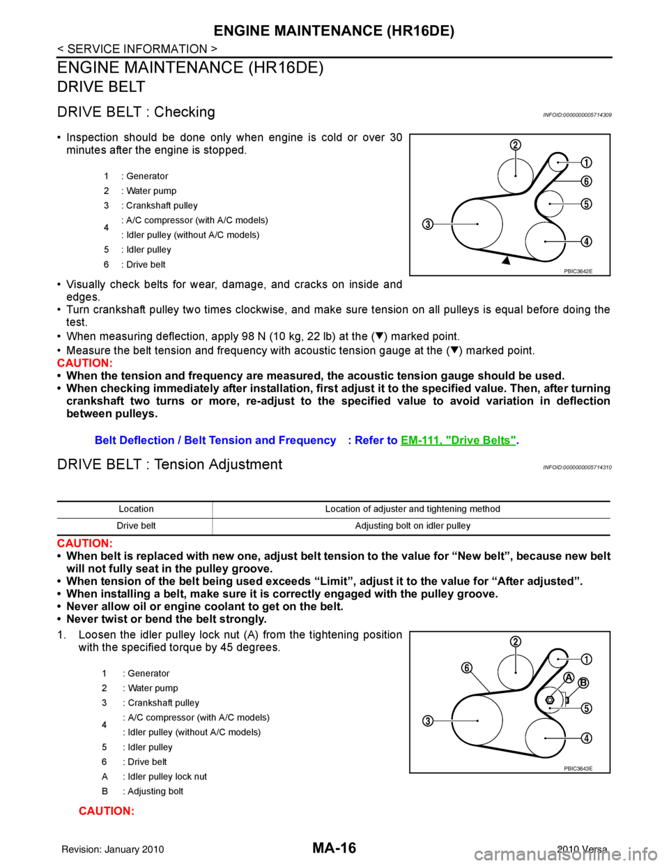
• Inspection should be done only when engine is cold or over 30minutes after the engine is stopped.
• Visually check belts for wear, damage, and cracks on inside and edges.
• Turn crankshaft pulley two times clockwise, and make sure tension on all pulleys is equal before doing the test.
• When measuring deflection, apply 98 N (10 kg, 22 lb) at the ( ) marked point.
• Measure the belt tension and frequency with acous tic tension gauge at the ( ) marked point.
CAUTION:
• When the tension and frequency are measured, the acoustic tension gauge should be used.
• When checking immediately after installation, first ad just it to the specified value. Then, after turning
crankshaft two turns or more, re-adjust to the specified value to avoid variation in deflection
between pulleys.
DRIVE BELT : Tension AdjustmentINFOID:0000000005714310
CAUTION:
• When belt is replaced with new one, adjust belt tension to the value for “New belt”, because new belt will not fully seat in the pulley groove.
• When tension of the belt being used exceeds “Limit”, adjust it to the value for “After adjusted”.
• When installing a belt, make sure it is correctly engaged with the pulley groove.
• Never allow oil or engine coolant to get on the belt.
• Never twist or bend the belt strongly.
1. Loosen the idler pulley lock nut (A) from the tightening position with the specified torque by 45 degrees.
CAUTION:
1 : Generator
2: Water pump
3 : Crankshaft pulley
4: A/C compressor (with A/C models)
: Idler pulley (without A/C models)
5 : Idler pulley
6: Drive belt
Belt Deflection / Belt Tension and Frequency : Refer to EM-111, "Drive Belts".
PBIC3642E
LocationLocation of adjuster and tightening method
Drive belt Adjusting bolt on idler pulley
1 : Generator
2: Water pump
3 : Crankshaft pulley
4 : A/C compressor
(with A/C models)
: Idler pulley (without A/C models)
5 : Idler pulley
6 : Drive belt
A : Idler pulley lock nut
B : Adjusting bolt
PBIC3643E
Revision: January 20102010 Versa
Page 3476 of 3745
PS-18
< SERVICE INFORMATION >
SERVICE DATA AND SPECIFICATIONS (SDS)
Steering Gear
INFOID:0000000005396943
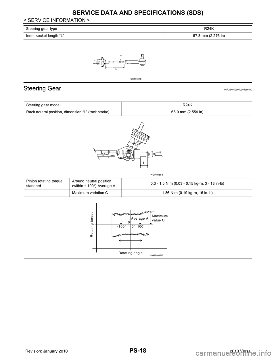
Inner socket length “L” 57.8 mm (2.276 in)
Steering gear type
R24K
SGIA0950E
Steering gear modelR24K
Rack neutral position, dimension “L ” (rack stroke) 65.0 mm (2.559 in)
Pinion rotating torque
standard Around neutral position
(within
± 100 °) Average A 0.3 - 1.5 N·m (0.03 - 0.15 kg-m, 3 - 13 in-lb)
Maximum variation C 1.86 N·m (0.19 kg-m, 16 in-lb)
WGIA0185E
MGIA0017E
Revision: January 20102010 Versa