RON 95 NISSAN TIIDA 2011 Service Repair Manual
[x] Cancel search | Manufacturer: NISSAN, Model Year: 2011, Model line: TIIDA, Model: NISSAN TIIDA 2011Pages: 3787, PDF Size: 78.35 MB
Page 3771 of 3787
FRONT WIPER AND WASHER SYSTEMWW-25
< SERVICE INFORMATION >
C
DE
F
G H
I
J
L
M A
B
WW
N
O P
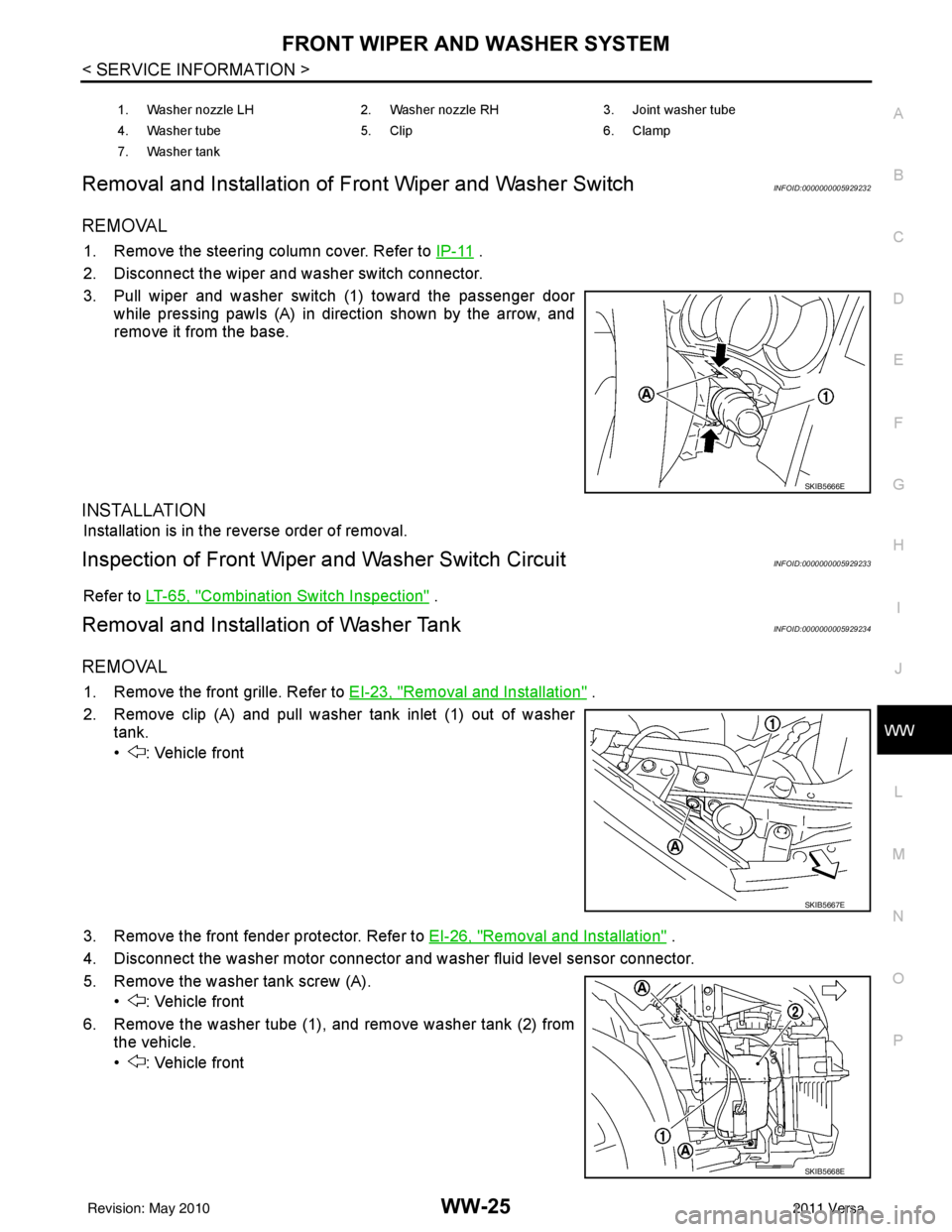
Removal and Installation of Front Wiper and Washer SwitchINFOID:0000000005929232
REMOVAL
1. Remove the steering column cover. Refer to IP-11 .
2. Disconnect the wiper and washer switch connector.
3. Pull wiper and washer switch (1) toward the passenger door while pressing pawls (A) in direction shown by the arrow, and
remove it from the base.
INSTALLATION
Installation is in the reverse order of removal.
Inspection of Front Wiper and Washer Switch CircuitINFOID:0000000005929233
Refer to LT-65, "Combination Switch Inspection" .
Removal and Installation of Washer TankINFOID:0000000005929234
REMOVAL
1. Remove the front grille. Refer to EI-23, "Removal and Installation" .
2. Remove clip (A) and pull washer tank inlet (1) out of washer tank.
• : Vehicle front
3. Remove the front fender protector. Refer to EI-26, "
Removal and Installation" .
4. Disconnect the washer motor connector and washer fluid level sensor connector.
5. Remove the washer tank screw (A). • : Vehicle front
6. Remove the washer tube (1), and remove washer tank (2) from the vehicle.
• : Vehicle front
1. Washer nozzle LH 2. Washer nozzle RH 3. Joint washer tube
4. Washer tube 5. Clip 6. Clamp
7. Washer tank
SKIB5666E
SKIB5667E
SKIB5668E
Revision: May 2010 2011 Versa
Page 3772 of 3787
WW-26
< SERVICE INFORMATION >
FRONT WIPER AND WASHER SYSTEM
INSTALLATION
Installation is in the reverse order of removal.
CAUTION:
After installation, add water up to the upper level of washer tank inlet, and check for water leaks.
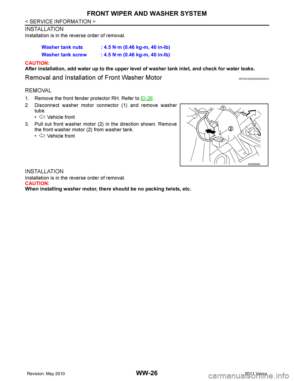
Removal and Installation of Front Washer MotorINFOID:0000000005929235
REMOVAL
1. Remove the front fender protector RH. Refer to EI-26 .
2. Disconnect washer motor connector (1) and remove washer tube.
• : Vehicle front
3. Pull out front washer motor (2) in the direction shown. Remove the front washer motor (2) from washer tank.
• : Vehicle front
INSTALLATION
Installation is in the reverse order of removal.
CAUTION:
When installing washer motor, there should be no packing twists, etc.
Washer tank nuts : 4.5 N·m (0.46 kg-m, 40 in-lb)
Washer tank screw : 4.5 N·m (0.46 kg-m, 40 in-lb)
SKIB5669E
Revision: May 2010
2011 Versa
Page 3773 of 3787
REAR WIPER AND WASHER SYSTEMWW-27
< SERVICE INFORMATION >
C
DE
F
G H
I
J
L
M A
B
WW
N
O P
REAR WIPER AND WASHER SYSTEM
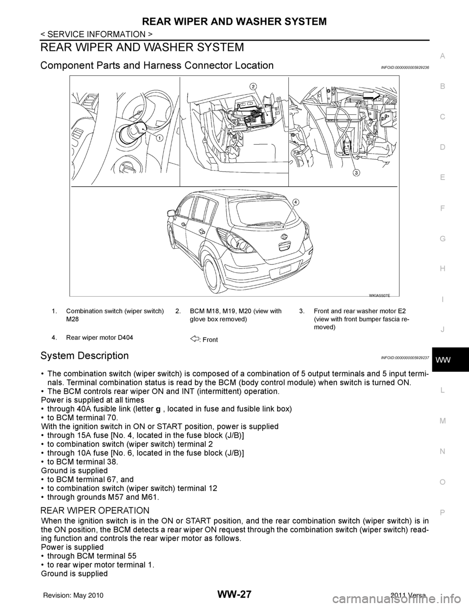
Component Parts and Har ness Connector LocationINFOID:0000000005929236
System DescriptionINFOID:0000000005929237
• The combination switch (wiper switch) is composed of a combination of 5 output terminals and 5 input termi-
nals. Terminal combination status is read by the BCM (body control module) when switch is turned ON.
• The BCM controls rear wiper ON and INT (intermittent) operation.
Power is supplied at all times
• through 40A fusible link (letter g , located in fuse and fusible link box)
• to BCM terminal 70.
With the ignition switch in ON or START position, power is supplied
• through 15A fuse [No. 4, located in the fuse block (J/B)]
• to combination switch (wiper switch) terminal 2
• through 10A fuse [No. 6, located in the fuse block (J/B)]
• to BCM terminal 38.
Ground is supplied
• to BCM terminal 67, and
• to combination switch (wiper switch) terminal 12
• through grounds M57 and M61.
REAR WIPER OPERATION
When the ignition switch is in the ON or START position, and the rear combination switch (wiper switch) is in
the ON position, the BCM detects a rear wiper ON r equest through the combination switch (wiper switch) read-
ing function and controls the rear wiper motor as follows.
Power is supplied
• through BCM terminal 55
• to rear wiper motor terminal 1.
Ground is supplied
WKIA5507E
1. Combination switch (wiper switch)
M28 2. BCM M18, M19, M20 (view with
glove box removed) 3. Front and rear washer motor E2
(view with front bumper fascia re-
moved)
4. Rear wiper motor D404 : Front
Revision: May 2010 2011 Versa
Page 3774 of 3787

WW-28
< SERVICE INFORMATION >
REAR WIPER AND WASHER SYSTEM
• to rear wiper motor terminal 3
• through grounds B117, B132 and D402.
With power and ground supplied, the rear wiper motor operates.
INTERMITTENT OPERATION
The rear wiper motor operates the wiper arm at low speed approximately every 7 seconds.
When the combination switch (wiper switch) is in the r ear wiper INT position, the BCM detects a rear wiper INT
request through the combination switch (wiper switch) reading function.
When BCM operates rear wiper motor, power is supplied
• through BCM terminal 55
• to rear wiper motor terminal 1.
Ground is supplied
• to rear wiper motor terminal 3
• through grounds B117, B132 and D402.
With power and ground supplied, the rear wiper operates in intermittent mode.
AUTO STOP OPERATION
When the rear wiper arm is not located at the base of the rear window, and the rear combination switch (wiper
switch) is turned OFF, the rear wiper motor will continue to operate until the rear wiper arm is at the base of the
rear window. When the rear wiper arm reaches the bas e, rear wiper motor terminals 2 and 1 are connected.
Ground is supplied
• to BCM terminal 44
• through rear wiper motor terminal 2, and
• through rear wiper motor terminal 3, and
• through grounds B117, B132 and D402.
REAR WASHER OPERATION
When the ignition switch is in the ON or START positi on, and the front and rear washer switches are OFF, the
front and rear washer motor is supplied power
• through 15A fuse [No. 4, located in the fuse block (J/B)]
• to combination switch (wiper switch) terminal 14
• through combination switch (wiper switch) terminal 11
• to front and rear washer motor terminal 2.
When the rear combination switch (wiper switch) is in rear washer position, the BCM detects a rear washer
signal by BCM combination switch (wiper switch) readi ng function. Combination switch (wiper switch) ground
is supplied
• to front and rear washer motor terminal 1
• through combination switch (wiper switch) terminal 13, and
• through combination switch (wiper switch) terminal 12
• through grounds M57 and M61.
With ground supplied, the front and rear washer motor is operated in the rear direction.
When the BCM detects that the rear washer motor has operated for 0.4 seconds or longer, BCM operates the
rear wiper motor.
When the BCM detects that the rear washer switch is in OFF, the rear wiper motor cycles approximately 3
times and then stops.
If the rear washer is operated with the rear combinati on switch (wiper switch) in the INT position, normal rear
wiper operation will take over. Once the rear washer switch is released the rear wiper will return to INT opera-
tion.
BCM Combination Switch (Wiper Switch) Reading Function
Refer to BCS-4, "System Description" .
Revision: May 2010 2011 Versa
Page 3783 of 3787
REAR WIPER AND WASHER SYSTEMWW-37
< SERVICE INFORMATION >
C
DE
F
G H
I
J
L
M A
B
WW
N
O P
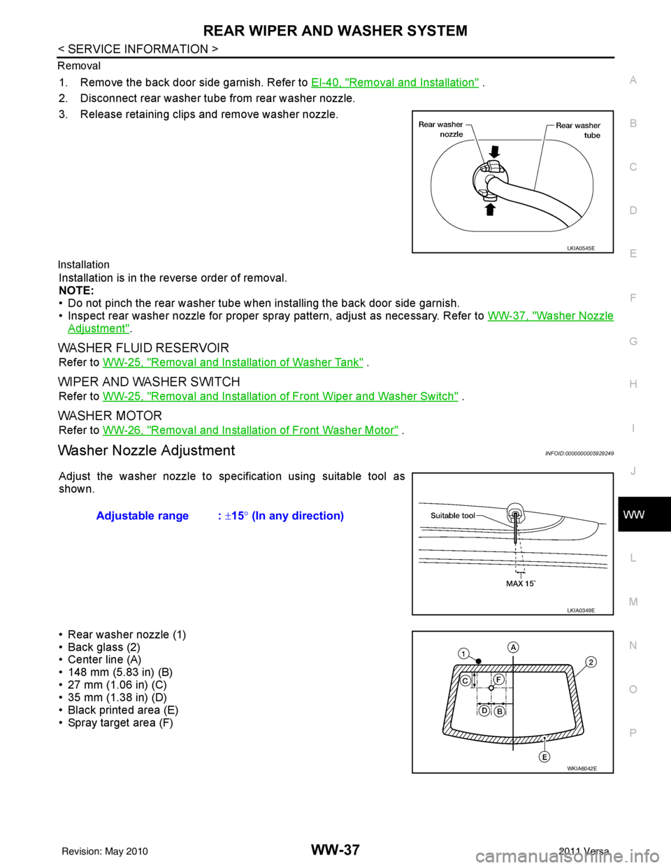
Removal
1. Remove the back door side garnish. Refer to
EI-40, "Removal and Installation" .
2. Disconnect rear washer tube from rear washer nozzle.
3. Release retaining clips and remove washer nozzle.
Installation
Installation is in the reverse order of removal.
NOTE:
• Do not pinch the rear washer tube when installing the back door side garnish.
• Inspect rear washer nozzle for proper spray pattern, adjust as necessary. Refer to WW-37, "
Washer Nozzle
Adjustment".
WASHER FLUID RESERVOIR
Refer to WW-25, "Removal and Installation of Washer Tank" .
WIPER AND WASHER SWITCH
Refer to WW-25, "Removal and Installation of Front Wiper and Washer Switch" .
WASHER MOTOR
Refer to WW-26, "Removal and Installation of Front Washer Motor" .
Washer Nozzle AdjustmentINFOID:0000000005929249
Adjust the washer nozzle to specification using suitable tool as
shown.
• Rear washer nozzle (1)
• Back glass (2)
• Center line (A)
• 148 mm (5.83 in) (B)
• 27 mm (1.06 in) (C)
• 35 mm (1.38 in) (D)
• Black printed area (E)
• Spray target area (F)
LKIA0545E
Adjustable range : ±15° (In any direction)
LKIA0349E
WKIA6042E
Revision: May 2010 2011 Versa
Page 3786 of 3787
WW-40
< SERVICE INFORMATION >
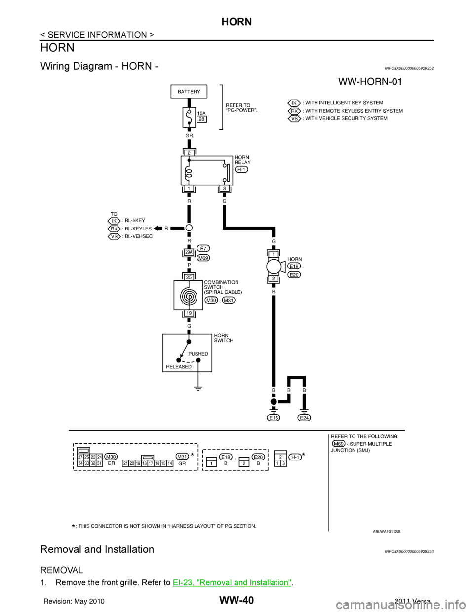
HORN
HORN
Wiring Diagram - HORN -INFOID:0000000005929252
Removal and InstallationINFOID:0000000005929253
REMOVAL
1. Remove the front grille. Refer to EI-23, "Removal and Installation".
ABLWA1011GB
Revision: May 2010 2011 Versa