Engine warning NISSAN TIIDA 2011 Service Repair Manual
[x] Cancel search | Manufacturer: NISSAN, Model Year: 2011, Model line: TIIDA, Model: NISSAN TIIDA 2011Pages: 3787, PDF Size: 78.35 MB
Page 3166 of 3787
![NISSAN TIIDA 2011 Service Repair Manual LU-18
< SERVICE INFORMATION >[MR18DE]
ENGINE OIL
4. Install oil pressure gauge and hose.
5. Start engine and warm it up to normal operating temperature.
6. Check oil pressure with engine running under](/img/5/57396/w960_57396-3165.png "NISSAN TIIDA 2011 Service Repair Manual LU-18
< SERVICE INFORMATION >[MR18DE]
ENGINE OIL
4. Install oil pressure gauge and hose.
5. Start engine and warm it up to normal operating temperature.
6. Check oil pressure with engine running under")
LU-18
< SERVICE INFORMATION >[MR18DE]
ENGINE OIL
4. Install oil pressure gauge and hose.
5. Start engine and warm it up to normal operating temperature.
6. Check oil pressure with engine running under no-load. Refer to LU-23, "
Standard and Limit".
If difference is extreme, check oil passage and oil pump for oil leaks.
NOTE:
When engine oil temperature is low, engine oil pressure becomes high.
7. After the inspections, install oil pressure switch as follows:
a. Remove old liquid gasket adhering to oil pressure switch and engine.
b. Apply liquid gasket and tighten oil pressure switch to specification. Use Genuine Silicone RTV Sealant or equivalent. Refer to GI-42, "
Recommended Chemical Product
and Sealant".
c. Check engine oil level.
d. After warming up engine, make sure there are no leaks of engine oil with running engine.
8. Install engine under cover. Refer to EI-15, "
Removal and Installation".
Changing Engine OilINFOID:0000000005928701
WARNING:
• Be careful not to burn yourself, as engine oil may be hot.
• Prolonged and repeated contact with used engine oil may cause ski n cancer. Try to avoid direct skin
contact with used engine oil. If skin contact is made, wash thoroughly with soap or hand cleaner as
soon as possible.
1. Warm up the engine, park vehicle on a level surface and check for engine oil leakage from engine compo- nents. Refer to LU-17, "
Inspection".
2. Stop the engine and wait for 10 minutes. Tool number : ST25051001 (J-25695-1)
: ST25052000 (J-25695-2)
WBIA0571E
Oil pressure switch : 14.7 N·m (1.5 kg-m, 11 ft-lb)
Revision: May 2010 2011 Versa
Page 3168 of 3787
![NISSAN TIIDA 2011 Service Repair Manual LU-20
< SERVICE INFORMATION >[MR18DE]
OIL FILTER
OIL FILTER
Removal and InstallationINFOID:0000000005928702
REMOVAL
1. Remove engine under cover. Refer to
EI-15, "Removal and Installation".
2. Drain](/img/5/57396/w960_57396-3167.png "NISSAN TIIDA 2011 Service Repair Manual LU-20
< SERVICE INFORMATION >[MR18DE]
OIL FILTER
OIL FILTER
Removal and InstallationINFOID:0000000005928702
REMOVAL
1. Remove engine under cover. Refer to
EI-15, \"Removal and Installation\".
2. Drain")
LU-20
< SERVICE INFORMATION >[MR18DE]
OIL FILTER
OIL FILTER
Removal and InstallationINFOID:0000000005928702
REMOVAL
1. Remove engine under cover. Refer to
EI-15, "Removal and Installation".
2. Drain engine oil. Refer to LU-18, "
Changing Engine Oil".
3. Remove oil filter using Tool (A). • : Front
WARNING:
• Be careful not to get burned ; engine and engine oil may
be hot.
CAUTION:
• Oil filter is provided with relief valve. Use Genuine NISSAN Oil Filter or equivalent.
• When removing, prepare a sh op cloth to absorb any
engine oil leakage or spillage.
• Do not spill engine oil on drive belt.
• Completely wipe off any engine oil th at spills on engine and vehicle.
INSTALLATION
1. Remove foreign materials adhering to the oil filter installation surface.
2. Apply new engine oil to the oil seal contact surface of new oil fil-
ter.
3. Screw oil filter manually until it touches the installation surface,
then tighten it by 2/3 turn. Or tighten to specification.
4. Refill engine with new engine oil. Refer to LU-18, "
Changing Engine Oil".
5. Install engine under cover. Refer to EI-15, "
Removal and Installation".
INSPECTION AFTER INSTALLATION
1. Check the engine oil level. Refer to LU-17, "Inspection".
2. Start engine, and make sure there are no engine oil leaks.
3. Stop engine and wait for 10 minutes.
4. Check the engine oil level and adjust as necessary. Refer to LU-17, "
Inspection".
Tool number : KV10115801 (J-38956)
PBIC3818E
SMA010
Oil filter: : 17.7 N·m (1.8 kg-m, 13 ft-lb)
SMA229B
Revision: May 2010
2011 Versa
Page 3174 of 3787
PRECAUTIONSMA-3
< SERVICE INFORMATION >
C
DE
F
G H
I
J
K
M A
B
MA
N
O P
SERVICE INFORMATION
PRECAUTIONS
Precaution for Supplemental Restraint System (SRS) "AIR BAG" and "SEAT BELT
PRE-TENSIONER"
INFOID:0000000005931125
The Supplemental Restraint System such as “AIR BAG” and “SEAT BELT PRE-TENSIONER”, used along
with a front seat belt, helps to reduce the risk or severi ty of injury to the driver and front passenger for certain
types of collision. This system includes seat belt switch inputs and dual stage front air bag modules. The SRS
system uses the seat belt switches to determine the front air bag deployment, and may only deploy one front
air bag, depending on the severity of a collision and w hether the front occupants are belted or unbelted.
Information necessary to service the system safely is included in the SRS and SB section of this Service Man-
ual.
WARNING:
• To avoid rendering the SRS inoper ative, which could increase the risk of personal injury or death in
the event of a collision which would result in air bag inflation, all maintenance must be performed by
an authorized NISSAN/INFINITI dealer.
• Improper maintenance, including in correct removal and installation of the SRS can lead to personal
injury caused by unintentional act ivation of the system. For removal of Spiral Cable and Air Bag
Module, see the SRS section.
• Do not use electrical test equipm ent on any circuit related to the SRS unless instructed to in this
Service Manual. SRS wiring harnesses can be identi fied by yellow and/or orange harnesses or har-
ness connectors.
PRECAUTIONS WHEN USING POWER TOOLS (AIR OR ELECTRIC) AND HAMMERS
WARNING:
• When working near the Airbag Diagnosis Sensor Un it or other Airbag System sensors with the Igni-
tion ON or engine running, DO NOT use air or el ectric power tools or strike near the sensor(s) with a
hammer. Heavy vibration could activate the sensor( s) and deploy the air bag(s), possibly causing
serious injury.
• When using air or electric power tools or hammers, always switch the Ignition OFF, disconnect the battery, and wait at least 3 minutes before performing any service.
Precaution Necessary for Steering Wheel Rotation After Battery Disconnect
INFOID:0000000005931126
NOTE:
• This Procedure is applied only to models with Intelligent Key system and NATS (NISSAN ANTI-THEFT SYS-
TEM).
• Remove and install all control units after disconnecti ng both battery cables with the ignition knob in the
″ LOCK ″ position.
• Always use CONSULT-III to perform self-diagnosis as a part of each function inspection after finishing work.
If DTC is detected, perform trouble diagnosis according to self-diagnostic results.
For models equipped with the Intelligent Key system and NATS , an electrically controlled steering lock mech-
anism is adopted on the key cylinder.
For this reason, if the battery is disconnected or if the battery is discharged, the steering wheel will lock and
steering wheel rotation will become impossible.
If steering wheel rotation is required when battery power is interrupted, follow the procedure below before
starting the repair operation.
OPERATION PROCEDURE
1. Connect both battery cables. NOTE:
Supply power using jumper cables if battery is discharged.
2. Use the Intelligent Key or mechanical key to turn the ignition switch to the ″ACC ″ position. At this time, the
steering lock will be released.
3. Disconnect both battery cables. The steering lock will remain released and the steering wheel can be
rotated.
4. Perform the necessary repair operation.
Revision: May 2010 2011 Versa
Page 3178 of 3787

GENERAL MAINTENANCEMA-7
< SERVICE INFORMATION >
C
DE
F
G H
I
J
K
M A
B
MA
N
O P
GENERAL MAINTENANCE
Explanation of Gene ral MaintenanceINFOID:0000000005931129
General MaintenanceINFOID:0000000005931130
General maintenance includes those items which shoul d be checked during the normal day-to-day operation
of the vehicle. They are essential if the vehicle is to continue operating properly. The owners can perform
checks and inspections themselves or have their NISSAN dealers do them.
OUTSIDE THE VEHICLE
The maintenance items listed here should be performed from time to time, unless otherwise specified.
INSIDE THE VEHICLE The maintenance items listed here should be checked on a regular basis, such as when performing periodic maintenance, cleaning the vehicle,
etc.
Item Reference page
Tires Check the pressure with a gauge often and always prior to long distance trips.
Adjust the pressure in all tires, including the spare, to the specified pressure.
Check carefully for damage, cuts or excessive wear. WT-28
Wheel nuts
When checking the tires, make sure no nuts are missing, and check for any loose
nuts. Tighten if necessary. WT-7
WindshieldClean the windshield on a regular basis. Check the windshield at least every six
months for cracks or other damage. Repair as necessary.
—
Tire rotation Tires should be rotated every 12,000 km (7,500 miles). WT-7
Tire Pressure Monitor
System (TPMS) trans-
mitter componentsReplace the TPMS transmitter grommet seal, valve core and cap when the tires
are replaced due to wear or age.
WT-9
Wheel alignment and
balanceIf the vehicle should pull to either side while driving on a straight and level road,
or if you detect uneven or abnormal tire wear, there may be a need for wheel
alignment. If the steering wheel or seat vibrates at normal highway speeds,
wheel balancing may be needed. FSU-7
and
WT-7
Windshield wiper
blades Check for cracks or wear if they do not wipe properly.
—
Doors and engine
hood Check that all doors and the engine hood operate smoothly as well as the trunk
lid and back hatch. Also make sure that all latches lock securely. Lubricate if nec-
essary. Make sure that the secondary latch keeps the hood from opening when
the primary latch is released.
When driving in areas using road salt or other corrosive materials, check lubrica-
tion frequently. MA-49
Lamps
Make sure that the headlamps, stop lamps, tail lamps, turn signal lamps, and oth-
er lamps are all operating properly and installed securely. Also check headlamp
aim. Clean the headlamps on a regular basis. —
Item
Reference page
Warning lamps and
chimes Make sure that all warning lamps and chimes are operating properly.
—
Windshield wiper and
washer Check that the wipers and washer operate properly and that the wipers do not
streak.
—
Windshield defroster Check that the air comes out of the defroster outlets properly and in sufficient
quantity when operating the heater or air conditioning. —
Steering wheel Check that it has the specified play. Check for changes in the steering condition,
such as excessive play, hard steering or strange noises.
Free play: Less than 35 mm (1.38 in) —
Seats Check seat position controls such as seat adjusters, seat back recliner, etc. to
make sure they operate smoothly and that all latches lock securely in every po-
sition. Check that the head restraints move up and down smoothly and that the
locks (if equipped) hold securely in all latched positions. Check that the latches
lock securely for folding-down rear seat backs. —
Revision: May 2010
2011 Versa
Page 3188 of 3787
ENGINE MAINTENANCE (HR16DE)MA-17
< SERVICE INFORMATION >
C
DE
F
G H
I
J
K
M A
B
MA
N
O P
• When the lock nut is loosened excessively, the idle r pulley tilts and the correct tension adjust-
ment cannot be performed. Never loo sen it excessively (more than 45 degrees).
• Put a matching mark on the lock nut, and check turning angle with a protractor. Never visually
check the tightening angle.
2. Adjust the belt tension by turning the adjusting bolt. CAUTION:
• When checking immediately after in stallation, first adjust it to the specified value. Then, after
turning crankshaft two turns or more, re-adjust to the specified value to avoid variation in deflec-
tion between pulleys.
• When the tension adjustment is performed, the lo ck nut should be in the condition at step“2”. If
the tension adjustment is performed when the lo ck nut is loosened more than the standard, the
idler pulley tilts and the correct tens ion adjustment cannot be performed.
3. Tighten the idler pulley lock nut.
ENGINE COOLANT
ENGINE COOLANT : InspectionINFOID:0000000005931139
LEVEL CHECK
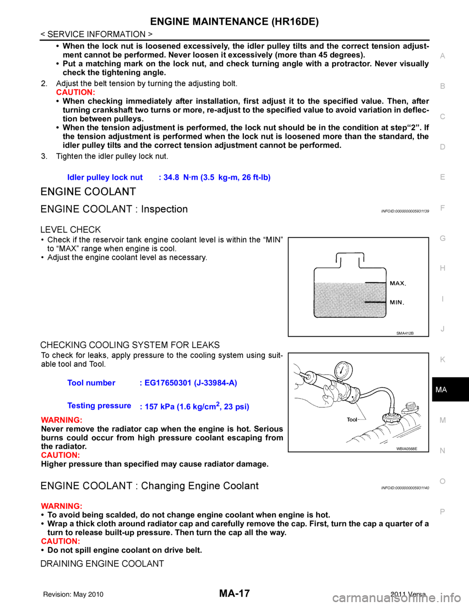
• Check if the reservoir tank engine coolant level is within the “MIN” to “MAX” range when engine is cool.
• Adjust the engine coolant level as necessary.
CHECKING COOLING SYSTEM FOR LEAKS
To check for leaks, apply pressure to the cooling system using suit-
able tool and Tool.
WARNING:
Never remove the radiator cap wh en the engine is hot. Serious
burns could occur from high pressure coolant escaping from
the radiator.
CAUTION:
Higher pressure than specified may cause radiator damage.
ENGINE COOLANT : Chang ing Engine CoolantINFOID:0000000005931140
WARNING:
• To avoid being scalded, do not change engine coolant when engine is hot.
• Wrap a thick cloth around radiator cap and carefully remove the cap. First, turn the cap a quarter of a
turn to release built-up pressure. Then turn the cap all the way.
CAUTION:
• Do not spill engine coolant on drive belt.
DRAINING ENGINE COOLANT
Idler pulley lock nut : 34.8 N·m (3.5 kg-m, 26 ft-lb)
SMA412B
Tool number : EG17650301 (J-33984-A)
Testing pressure : 157 kPa (1.6 kg/cm
2, 23 psi)
WBIA0568E
Revision: May 2010 2011 Versa
Page 3192 of 3787
ENGINE MAINTENANCE (HR16DE)MA-21
< SERVICE INFORMATION >
C
DE
F
G H
I
J
K
M A
B
MA
N
O P
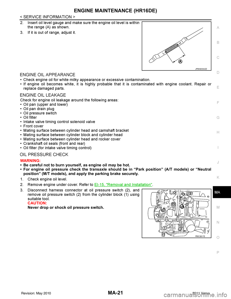
2. Insert oil level gauge and make sure the engine oil level is within the range (A) as shown.
3. If it is out of range, adjust it.
ENGINE OIL APPEARANCE
• Check engine oil for white milky appearance or excessive contamination.
• If engine oil becomes white, it is highly probable t hat it is contaminated with engine coolant. Repair or
replace damaged parts.
ENGINE OIL LEAKAGE
Check for engine oil leakage around the following areas:
• Oil pan (upper and lower)
• Oil pan drain plug
• Oil pressure switch
• Oil filter
• Intake valve timing control solenoid valve
• Front cover
• Mating surface between cylinder head and camshaft bracket
• Mating surface between cylinder block and cylinder head
• Mating surface between cylinder head and rocker cover
• Crankshaft oil seals (front and rear)
• Oil filter (for intake valve timing control)
OIL PRESSURE CHECK
WARNING:
• Be careful not to burn yoursel f, as engine oil may be hot.
• For engine oil pressure check the transaxle should be in “Park position” (A/T models) or “Neutral
position” (M/T models), and apply the parking brake securely.
1. Check engine oil level.
2. Remove engine under cover. Refer to EI-15, "
Removal and Installation".
3. Disconnect harness connector at oil pressure switch (2), and remove oil pressure switch (2) from the cylinder block (1) using
suitable tool.
CAUTION:
Never drop or shock oil pressure switch.
JPBIA0554ZZ
PBIC3817E
Revision: May 2010 2011 Versa
Page 3193 of 3787
MA-22
< SERVICE INFORMATION >
ENGINE MAINTENANCE (HR16DE)
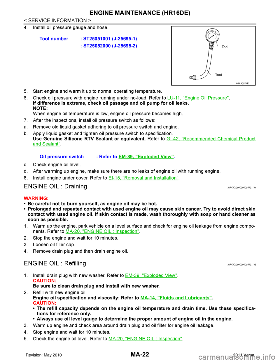
4. Install oil pressure gauge and hose.
5. Start engine and warm it up to normal operating temperature.
6. Check oil pressure with engine running under no-load. Refer to LU-11, "
Engine Oil Pressure".
If difference is extreme, check oil passage and oil pump for oil leaks.
NOTE:
When engine oil temperature is low, engine oil pressure becomes high.
7. After the inspections, install oil pressure switch as follows:
a. Remove old liquid gasket adhering to oil pressure switch and engine.
b. Apply liquid gasket and tighten oil pressure switch to specification. Use Genuine Silicone RTV Sealant or equivalent. Refer to GI-42, "
Recommended Chemical Product
and Sealant".
c. Check engine oil level.
d. After warming up engine, make sure there are no leaks of engine oil with running engine.
8. Install engine under cover. Refer to EI-15, "
Removal and Installation".
ENGINE OIL : DrainingINFOID:0000000005931144
WARNING:
• Be careful not to burn yourself, as engine oil may be hot.
• Prolonged and repeated contact with used engine oil may cause ski n cancer. Try to avoid direct skin
contact with used engine oil. If skin contact is made, wash thoroughly with soap or hand cleaner as
soon as possible.
1. Warm up the engine, park vehicle on a level surface and check for engine oil leakage from engine compo- nents. Refer to MA-20, "
ENGINE OIL : Inspection".
2. Stop the engine and wait for 10 minutes.
3. Loosen oil filler cap.
4. Remove drain plug and then drain engine oil.
ENGINE OIL : RefillingINFOID:0000000005931145
1. Install drain plug with new washer. Refer to EM-39, "Exploded View".
CAUTION:
Be sure to clean drain plug and install with new washer.
2. Refill with new engine oil. Engine oil specification and viscosity: Refer to MA-14, "
Fluids and Lubricants".
CAUTION:
• The refill capacity depends on the engine oi l temperature and drain time. Use these specifica-
tions for reference only.
• Always use oil level gauge to determine the pr oper amount of engine oil in the engine.
3. Warm up engine and check area around drain plug and oil filter for engine oil leakage.
4. Stop engine and wait for 10 minutes.
5. Check the engine oil level. Refer to MA-20, "
ENGINE OIL : Inspection".
Tool number : ST25051001 (J-25695-1)
: ST25052000 (J-25695-2)
WBIA0571E
Oil pressure switch : Refer to EM-89, "Exploded View".
Revision: May 2010 2011 Versa
Page 3194 of 3787
ENGINE MAINTENANCE (HR16DE)MA-23
< SERVICE INFORMATION >
C
DE
F
G H
I
J
K
M A
B
MA
N
O P
OIL FILTER
OIL FILTER : Remova l and InstallationINFOID:0000000005931146
REMOVAL
1. Remove engine under cover. Refer to EI-15, "Removal and Installation".
2. Drain engine oil. Refer to MA-22, "
ENGINE OIL : Draining".
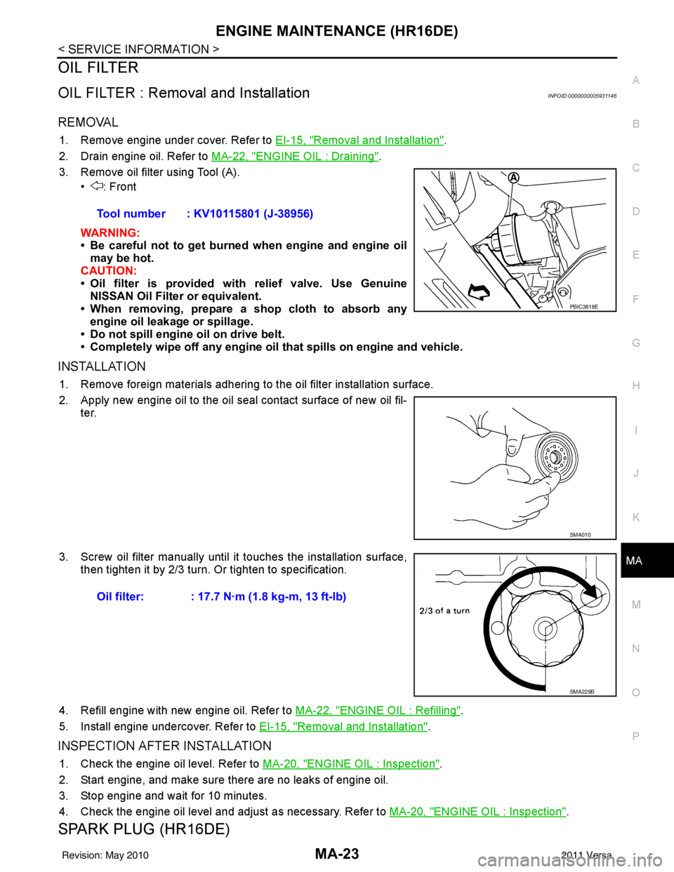
3. Remove oil filter using Tool (A). • : Front
WARNING:
• Be careful not to get burned when engine and engine oil
may be hot.
CAUTION:
• Oil filter is provided with relief valve. Use Genuine
NISSAN Oil Filter or equivalent.
• When removing, prepare a s hop cloth to absorb any
engine oil leakage or spillage.
• Do not spill engine oil on drive belt.
• Completely wipe off any engine oil that spills on engine and vehicle.
INSTALLATION
1. Remove foreign materials adhering to the oil filter installation surface.
2. Apply new engine oil to the oil seal contact surface of new oil fil-
ter.
3. Screw oil filter manually until it touches the installation surface,
then tighten it by 2/3 turn. Or tighten to specification.
4. Refill engine with new engine oil. Refer to MA-22, "
ENGINE OIL : Refilling".
5. Install engine undercover. Refer to EI-15, "
Removal and Installation".
INSPECTION AFTER INSTALLATION
1. Check the engine oil level. Refer to MA-20, "ENGINE OIL : Inspection".
2. Start engine, and make sure there are no leaks of engine oil.
3. Stop engine and wait for 10 minutes.
4. Check the engine oil level and adjust as necessary. Refer to MA-20, "
ENGINE OIL : Inspection".
SPARK PLUG (HR16DE)
Tool number : KV10115801 (J-38956)
PBIC3818E
SMA010
Oil filter: : 17.7 N·m (1.8 kg-m, 13 ft-lb)
SMA229B
Revision: May 2010 2011 Versa
Page 3197 of 3787
MA-26
< SERVICE INFORMATION >
ENGINE MAINTENANCE (MR18DE)
ENGINE MAINTENANCE (MR18DE)
DRIVE BELT
DRIVE BELT : ComponentINFOID:0000000005931150
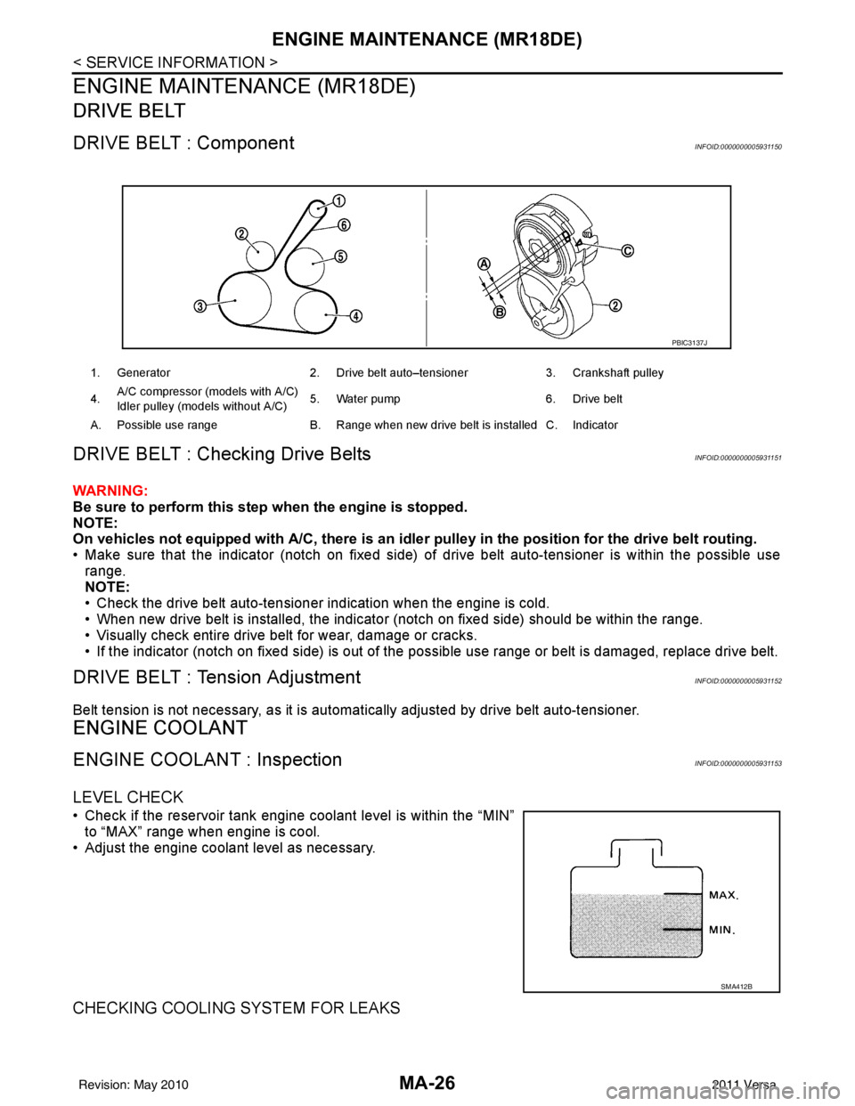
DRIVE BELT : Checking Drive BeltsINFOID:0000000005931151
WARNING:
Be sure to perform this step when the engine is stopped.
NOTE:
On vehicles not equipped with A/C, there is an idler pulley in the position for the drive belt routing.
• Make sure that the indicator (notch on fixed side) of drive belt auto-tensioner is within the possible use
range.
NOTE:
• Check the drive belt auto-tensioner indication when the engine is cold.
• When new drive belt is installed, the indicator (notch on fixed side) should be within the range.
• Visually check entire drive belt for wear, damage or cracks.
• If the indicator (notch on fixed side) is out of t he possible use range or belt is damaged, replace drive belt.
DRIVE BELT : Tension AdjustmentINFOID:0000000005931152
Belt tension is not necessary, as it is automatically adjusted by drive belt auto-tensioner.
ENGINE COOLANT
ENGINE COOLANT : InspectionINFOID:0000000005931153
LEVEL CHECK
• Check if the reservoir tank engine coolant level is within the “MIN”
to “MAX” range when engine is cool.
• Adjust the engine coolant level as necessary.
CHECKING COOLING SYSTEM FOR LEAKS
1. Generator 2. Drive belt auto–tensioner 3. Crankshaft pulley
4. A/C compressor (models with A/C)
Idler pulley (models without A/C)
5. Water pump
6. Drive belt
A. Possible use range B. Range when new drive belt is installed C. Indicator
PBIC3137J
SMA412B
Revision: May 2010 2011 Versa
Page 3198 of 3787
ENGINE MAINTENANCE (MR18DE)MA-27
< SERVICE INFORMATION >
C
DE
F
G H
I
J
K
M A
B
MA
N
O P
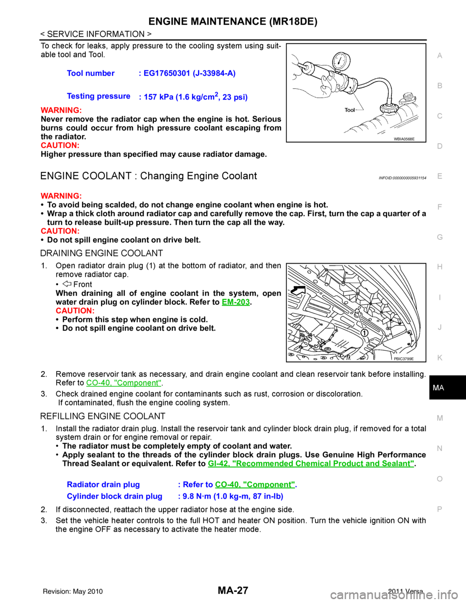
To check for leaks, apply pressure to the cooling system using suit-
able tool and Tool.
WARNING:
Never remove the radiator cap wh en the engine is hot. Serious
burns could occur from high pressure coolant escaping from
the radiator.
CAUTION:
Higher pressure than specified may cause radiator damage.
ENGINE COOLANT : Chang ing Engine CoolantINFOID:0000000005931154
WARNING:
• To avoid being scalded, do not change engine coolant when engine is hot.
• Wrap a thick cloth around radiator cap and carefully remove the cap. First, turn the cap a quarter of a
turn to release built-up pressure. Then turn the cap all the way.
CAUTION:
• Do not spill engine coolant on drive belt.
DRAINING ENGINE COOLANT
1. Open radiator drain plug (1) at the bottom of radiator, and then remove radiator cap.
• Front
When draining all of engine coolant in the system, open
water drain plug on cylinder block. Refer to EM-203
.
CAUTION:
• Perform this step when engine is cold.
• Do not spill engine coolant on drive belt.
2. Remove reservoir tank as necessary, and drain engi ne coolant and clean reservoir tank before installing.
Refer to CO-40, "
Component".
3. Check drained engine coolant for contaminants such as rust, corrosion or discoloration. If contaminated, flush the engine cooling system.
REFILLING ENGINE COOLANT
1. Install the radiator drain plug. Install the reservoir tank and cylinder block drain plug, if removed for a total
system drain or for engine removal or repair.
• The radiator must be completely empty of coolant and water.
• Apply sealant to the threads of the cylinder blo ck drain plugs. Use Genuine High Performance
Thread Sealant or equivalent. Refer to GI-42, "
Recommended Chemical Product and Sealant".
2. If disconnected, reattach the upper radiator hose at the engine side.
3. Set the vehicle heater controls to the full HOT and heat er ON position. Turn the vehicle ignition ON with
the engine OFF as necessary to activate the heater mode. Tool number : EG17650301 (J-33984-A)
Testing pressure
: 157 kPa (1.6 kg/cm
2, 23 psi)
WBIA0568E
PBIC3799E
Radiator drain plug : Refer to CO-40, "Component".
Cylinder block drain plug : 9.8 N·m (1.0 kg-m, 87 in-lb)
Revision: May 2010 2011 Versa