Engine warning NISSAN TIIDA 2011 Service Repair Manual
[x] Cancel search | Manufacturer: NISSAN, Model Year: 2011, Model line: TIIDA, Model: NISSAN TIIDA 2011Pages: 3787, PDF Size: 78.35 MB
Page 3602 of 3787
SC-24
< SERVICE INFORMATION >
CHARGING SYSTEM
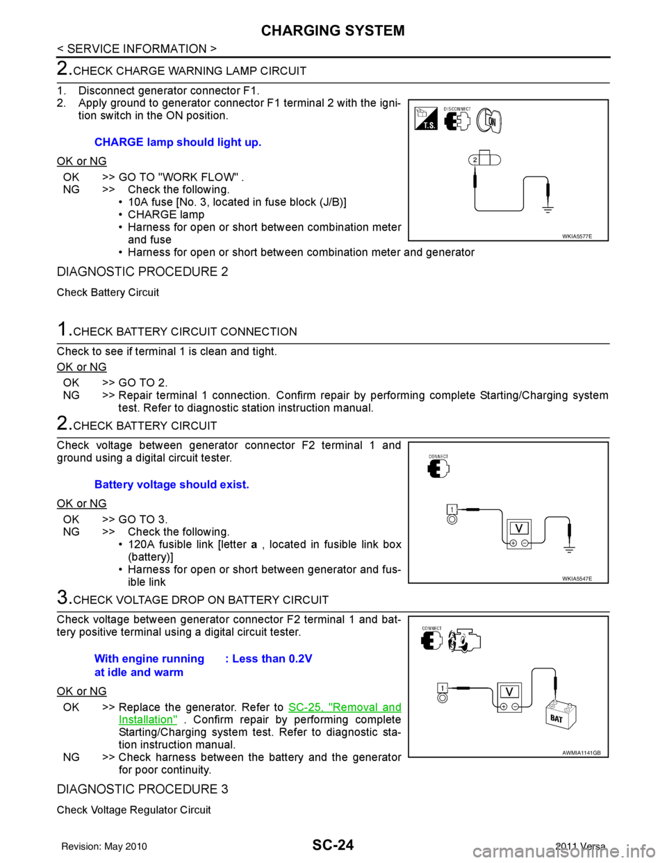
2.CHECK CHARGE WARNING LAMP CIRCUIT
1. Disconnect generator connector F1.
2. Apply ground to generator connector F1 terminal 2 with the igni- tion switch in the ON position.
OK or NG
OK >> GO TO "WORK FLOW" .
NG >> Check the following. • 10A fuse [No. 3, located in fuse block (J/B)]
• CHARGE lamp
• Harness for open or short between combination meterand fuse
• Harness for open or short between combination meter and generator
DIAGNOSTIC PROCEDURE 2
Check Battery Circuit
1.CHECK BATTERY CIRCUIT CONNECTION
Check to see if terminal 1 is clean and tight.
OK or NG
OK >> GO TO 2.
NG >> Repair terminal 1 connection. Confirm repair by performing complete Starting/Charging system test. Refer to diagnostic station instruction manual.
2.CHECK BATTERY CIRCUIT
Check voltage between generator connector F2 terminal 1 and
ground using a digital circuit tester.
OK or NG
OK >> GO TO 3.
NG >> Check the following. • 120A fusible link [letter a , located in fusible link box
(battery)]
• Harness for open or short between generator and fus- ible link
3.CHECK VOLTAGE DROP ON BATTERY CIRCUIT
Check voltage between generator connector F2 terminal 1 and bat-
tery positive terminal using a digital circuit tester.
OK or NG
OK >> Replace the generator. Refer to SC-25, "Removal and
Installation" . Confirm repair by performing complete
Starting/Charging system test. Refer to diagnostic sta-
tion instruction manual.
NG >> Check harness between the battery and the generator for poor continuity.
DIAGNOSTIC PROCEDURE 3
Check Voltage Regulator Circuit
CHARGE lamp should light up.
WKIA5577E
Battery voltage should exist.
WKIA5547E
With engine running
at idle and warm : Less than 0.2V
AWMIA1141GB
Revision: May 2010
2011 Versa
Page 3607 of 3787

SE-2
< SERVICE INFORMATION >
PRECAUTIONS
SERVICE INFORMATION
PRECAUTIONS
Precaution for Supplemental Restraint System (SRS) "AIR BAG" and "SEAT BELT
PRE-TENSIONER"
INFOID:0000000006410247
The Supplemental Restraint System such as “A IR BAG” and “SEAT BELT PRE-TENSIONER”, used along
with a front seat belt, helps to reduce the risk or severity of injury to the driver and front passenger for certain
types of collision. This system includes seat belt switch inputs and dual stage front air bag modules. The SRS
system uses the seat belt switches to determine the front air bag deployment, and may only deploy one front
air bag, depending on the severity of a collision and w hether the front occupants are belted or unbelted.
Information necessary to service the system safely is included in the SRS and SB section of this Service Man-
ual.
WARNING:
• To avoid rendering the SRS inopera tive, which could increase the risk of personal injury or death in
the event of a collision which would result in air bag inflation, all maintenance must be performed by
an authorized NISSAN/INFINITI dealer.
• Improper maintenance, including incorrect removal and installation of the SRS can lead to personal
injury caused by unintent ional activation of the system. For re moval of Spiral Cable and Air Bag
Module, see the SRS section.
• Do not use electrical test equipmen t on any circuit related to the SRS unless instructed to in this
Service Manual. SRS wiring harn esses can be identified by yellow and/or orange harnesses or har-
ness connectors.
PRECAUTIONS WHEN USING POWER TOOLS (AIR OR ELECTRIC) AND HAMMERS
WARNING:
• When working near the Airbag Diagnosis Sensor Unit or other Airbag System sensors with the Igni-
tion ON or engine running, DO NOT use air or electri c power tools or strike near the sensor(s) with a
hammer. Heavy vibration could activate the sensor( s) and deploy the air bag(s), possibly causing
serious injury.
• When using air or electric power tools or hammers , always switch the Ignition OFF, disconnect the
battery, and wait at least 3 minu tes before performing any service.
Precaution Necessary for Steering W heel Rotation After Battery Disconnect
INFOID:0000000005929596
NOTE:
• This Procedure is applied only to models with Intelligent Key system and NATS (NISSAN ANTI-THEFT SYS-
TEM).
• Remove and install all control units after disconnecting both battery cables with the ignition knob in the
″LOCK ″ position.
• Always use CONSULT-III to perform self-diagnosis as a part of each function inspection after finishing work.
If DTC is detected, perform trouble diagnosis according to self-diagnostic results.
For models equipped with the Intelligent Key system and NATS, an electrically controlled steering lock mech-
anism is adopted on the key cylinder.
For this reason, if the battery is disconnected or if the battery is discharged, the steering wheel will lock and
steering wheel rotation will become impossible.
If steering wheel rotation is required when battery pow er is interrupted, follow the procedure below before
starting the repair operation.
OPERATION PROCEDURE
1. Connect both battery cables. NOTE:
Supply power using jumper cables if battery is discharged.
2. Use the Intelligent Key or mechanical key to turn the ignition switch to the ″ACC ″ position. At this time, the
steering lock will be released.
3. Disconnect both battery cables. The steering lock will remain released and the steering wheel can be rotated.
4. Perform the necessary repair operation.
Revision: May 2010 2011 Versa
Page 3636 of 3787

SRS-2
< PRECAUTION >
PRECAUTIONS
PRECAUTION
PRECAUTIONS
Precaution for Supplemental Restraint System (SRS) "AIR BAG" and "SEAT BELT
PRE-TENSIONER"
INFOID:0000000006211104
The Supplemental Restraint System such as “A IR BAG” and “SEAT BELT PRE-TENSIONER”, used along
with a front seat belt, helps to reduce the risk or severity of injury to the driver and front passenger for certain
types of collision. This system includes seat belt switch inputs and dual stage front air bag modules. The SRS
system uses the seat belt switches to determine the front air bag deployment, and may only deploy one front
air bag, depending on the severity of a collision and w hether the front occupants are belted or unbelted.
Information necessary to service the system safely is included in the SRS and SB section of this Service Man-
ual.
WARNING:
• To avoid rendering the SRS inopera tive, which could increase the risk of personal injury or death in
the event of a collision which would result in air bag inflation, all maintenance must be performed by
an authorized NISSAN/INFINITI dealer.
• Improper maintenance, including in correct removal and installation of the SRS, can lead to personal
injury caused by unintent ional activation of the system. For re moval of Spiral Cable and Air Bag
Module, see the SRS section.
• Do not use electrical test equipmen t on any circuit related to the SRS unless instructed to in this
Service Manual. SRS wiring harn esses can be identified by yellow and/or orange harnesses or har-
ness connectors.
PRECAUTIONS WHEN USING POWER TOOLS (AIR OR ELECTRIC) AND HAMMERS
WARNING:
• When working near the Airbag Diagnosis Sensor Unit or other Airbag System sensors with the Igni-
tion ON or engine running, DO NOT use air or electri c power tools or strike near the sensor(s) with a
hammer. Heavy vibration could activate the sensor( s) and deploy the air bag(s), possibly causing
serious injury.
• When using air or electric power tools or hammers , always switch the Ignition OFF, disconnect the
battery, and wait at least 3 minu tes before performing any service.
Precaution for SRS "AIR BAG" and "S EAT BELT PRE-TENSIONER" Service
INFOID:0000000006211105
• Do not use electrical test equipment to check SRS ci rcuits unless instructed to in this Service Manual.
• Before servicing the SRS, turn ignition switch OFF, disconnect both battery cables and wait at least 3 min- utes.
For approximately 3 minutes after the cables are removed, it is still possible for the air bag and seat belt pre-
tensioner to deploy. Therefore, do not work on any SR S connectors or wires until at least 3 minutes have
passed.
• The air bag diagnosis sensor unit must always be installed with the arrow mark “ ⇐” pointing toward the front
of the vehicle for proper operation. Also check air bag diagnosis sensor unit for cracks, deformities or rust
before installation and replace as required.
• The spiral cable must be aligned with the neutral position since its rotations are limited. Do not attempt to
turn steering wheel or column after removal of steering gear.
• Handle air bag module carefully. Always place driver and front passenger air bag modules with the pad side facing upward and seat mounted front side air bag module standing with the stud bolt side facing down.
• Conduct self-diagnosis to check entire SRS for proper function after replacing any components.
• After air bag inflates, the front instrument panel assembly should be replaced if damaged.
• Do not reuse center pillar upper garnish if removed.
Precaution Necessary for Steering W heel Rotation After Battery Disconnect
INFOID:0000000006211106
NOTE:
• This Procedure is applied only to models with Intelligent Key system and NATS (NISSAN ANTI-THEFT SYS-
TEM).
• Remove and install all control units after disconnecting both battery cables with the ignition knob in the
″LOCK ″ position.
Revision: May 2010 2011 Versa
Page 3688 of 3787

STC-1
STEERING
C
DE
F
H I
J
K L
M
SECTION STC
A
B
STC
N
O P
CONTENTS
STEERING CONTROL SYSTEM
EPS
BASIC INSPECTION ....... .............................
3
DIAGNOSIS AND REPAIR WORKFLOW ..... .....3
Work Flow ........................................................... ......3
SYSTEM DESCRIPTION ..............................5
EPS SYSTEM ... .............................................. .....5
System Diagram .................................................. ......5
System Description ...................................................5
Component Parts Location ........................................6
Component Description .............................................6
DIAGNOSIS SYSTEM (EPS CONTROL UNIT)
.....
8
CONSULT-III Function ........................................ ......8
DTC/CIRCUIT DIAGNOSIS ..........................9
C1601 BATTERY POWER SUPPLY ..................9
Description .......................................................... ......9
DTC Logic .................................................................9
Diagnosis Procedure .................................................9
C1604 TORQUE SENSOR .................................11
Description ..............................................................11
DTC Logic ...............................................................11
Diagnosis Procedure ...............................................11
C1606 EPS MOTOR ...........................................13
Description .......................................................... ....13
DTC Logic ...............................................................13
Diagnosis Procedure ...............................................13
Component Inspection ............................................13
C1607, C1608 EPS CONTROL UNIT ................15
Description .......................................................... ....15
DTC Logic ...............................................................15
Diagnosis Procedure ...............................................15
C1609 VEHICLE SPEED SIGNAL .....................16
Description ........................................................... ....16
DTC Logic ................................................................16
Diagnosis Procedure ...............................................16
C1610 ENGINE STATUS SIGNAL ...................17
Description ...............................................................17
DTC Logic ................................................................17
Diagnosis Procedure ...............................................17
U1000 CAN COMM CIRCUIT ...........................18
Description ...............................................................18
DTC Logic ................................................................18
Diagnosis Procedure ...............................................18
EPS WARNING LAMP ......................................19
Description ...............................................................19
Component Function Check ....................................19
Diagnosis Procedure ...............................................19
ECU DIAGNOSIS INFORMATION ..............20
EPS CONTROL UNIT .......................................20
Reference Value .................................................. ....20
Wiring Diagram - ELECTRONICALLY CON-
TROLLED POWER STEERING SYSTEM - ............
22
Fail-Safe .............................................................. ....23
DTC Inspection Priority Chart ..................................24
DTC Index ...............................................................24
SYMPTOM DIAGNOSIS ..............................25
EPS WARNING LAMP DOES NOT TURN ON ...25
Description ........................................................... ....25
Diagnosis Procedure ...............................................25
EPS WARNING LAMP DOES NOT TURN
OFF ....................................................................
26
Description ...............................................................26
Diagnosis Procedure ...............................................26
STEERING WHEEL TURNING FORCE IS
HEAVY OR LIGHT ............................................
27
Revision: May 2010 2011 Versa
Page 3693 of 3787
![NISSAN TIIDA 2011 Service Repair Manual STC-6
< SYSTEM DESCRIPTION >[EPS]
EPS SYSTEM
Component Parts Location
INFOID:0000000005931226
Component DescriptionINFOID:0000000005931227
Combination meter • Transmits mainly the following signals](/img/5/57396/w960_57396-3692.png "NISSAN TIIDA 2011 Service Repair Manual STC-6
< SYSTEM DESCRIPTION >[EPS]
EPS SYSTEM
Component Parts Location
INFOID:0000000005931226
Component DescriptionINFOID:0000000005931227
Combination meter • Transmits mainly the following signals")
STC-6
< SYSTEM DESCRIPTION >[EPS]
EPS SYSTEM
Component Parts Location
INFOID:0000000005931226
Component DescriptionINFOID:0000000005931227
Combination meter • Transmits mainly the following signals to EPS control unit via CAN communication.
Vehicle speed signal
• EPS warning lamp si gnal is received from the EPS co ntrol unit via CAN communication.
TCM (Without ABS) Transmits the following si
gnals via CAN communicatio n to EPS control until.
Engine status signal
• Vehicle speed signal
Control unit
Signal status
SGIA1623E
Components parts Reference
EPS control unit STC-15, "
Description"
EPS motorSTC-13, "Description"
Torque sensor STC-11, "Description"
Revision: May 2010 2011 Versa
Page 3695 of 3787
![NISSAN TIIDA 2011 Service Repair Manual STC-8
< SYSTEM DESCRIPTION >[EPS]
DIAGNOSIS SYSTEM (EPS CONTROL UNIT)
DIAGNOSIS SYSTEM
(EPS CONTROL UNIT)
CONSULT-III FunctionINFOID:0000000005931228
FUNCTION
CONSULT-III can display each diagnostic](/img/5/57396/w960_57396-3694.png "NISSAN TIIDA 2011 Service Repair Manual STC-8
< SYSTEM DESCRIPTION >[EPS]
DIAGNOSIS SYSTEM (EPS CONTROL UNIT)
DIAGNOSIS SYSTEM
(EPS CONTROL UNIT)
CONSULT-III FunctionINFOID:0000000005931228
FUNCTION
CONSULT-III can display each diagnostic")
STC-8
< SYSTEM DESCRIPTION >[EPS]
DIAGNOSIS SYSTEM (EPS CONTROL UNIT)
DIAGNOSIS SYSTEM
(EPS CONTROL UNIT)
CONSULT-III FunctionINFOID:0000000005931228
FUNCTION
CONSULT-III can display each diagnostic item us ing the diagnostic test modes shown following.
ECU IDENTIFICATION
Displays the part number stored in the control unit.
SELF-DIAG RESULTS MODE
Display Item List
Refer to STC-24, "DTC Index".
CAUTION:
If “CAN COMM CIRCUIT [U1000]” is disp layed with other DTCs, first perform the trouble diagnosis for
CAN communication line.
DATA MONITOR MODE
Display Item List
*1: Almost in accordance with the value of MOTOR SIG. It is not a malfunction though these values are not accorded when steerin g
quickly.
*2: It is not a malfunction, though it might not be corresponding just after ignition switch in turned ON. Diagnostic test mode
Function
ECU identification Steering column assembly number can be read.
Self diagnostic result Self-diagnostic results can be read and erased quickly.
CAN diag support MNTR The results of transmit/receive diagnosis of CAN communication can be read.
Data monitor Input/Output data in the EPS control unit can be read.
Monitor item (Unit) Remarks
BATTERY VOLT (V) Displays the power supply voltage for EPS control unit.
TORQUE SENSOR (Nm) Displays steering wheel turning force detected by torque sensor.
MOTOR CURRENT (A) Displays the current value consumed by EPS motor.
MOTOR SIG (A)
*1Displays the current commanded value to EPS motor.
VEHICLE SPEED (km/h) or (MPH)
*2Vehicle speed is displayed from vehicle speed signal via CAN communication.
WARNING LAMP (On/Off) EPS warning lamp control status is displayed.
ENGINE STATUS (Stop/Run) Engine speed is displayed from engine status signal via CAN communication.
Revision: May 2010 2011 Versa
Page 3706 of 3787
![NISSAN TIIDA 2011 Service Repair Manual EPS WARNING LAMPSTC-19
< DTC/CIRCUIT DIAGNOSIS > [EPS]
C
D
E
F
H I
J
K L
M A
B
STC
N
O P
EPS WARNING LAMP
DescriptionINFOID:0000000005931251
• Turn ON when there is a malfunction in EPS system. If](/img/5/57396/w960_57396-3705.png "NISSAN TIIDA 2011 Service Repair Manual EPS WARNING LAMPSTC-19
< DTC/CIRCUIT DIAGNOSIS > [EPS]
C
D
E
F
H I
J
K L
M A
B
STC
N
O P
EPS WARNING LAMP
DescriptionINFOID:0000000005931251
• Turn ON when there is a malfunction in EPS system. If")
EPS WARNING LAMPSTC-19
< DTC/CIRCUIT DIAGNOSIS > [EPS]
C
D
E
F
H I
J
K L
M A
B
STC
N
O P
EPS WARNING LAMP
DescriptionINFOID:0000000005931251
• Turn ON when there is a malfunction in EPS system. If indicates that fail-safe mode is engaged and enters a
manual steering state (Control turning force steering wheel becomes heavy).
• Also turns ON when ignition switch is turned ON, for purpose of lamp check. Turns OFF after the engine
starts, if system is normal.
EPS WARNING LAMP INDICATION
CAUTION:
EPS warning lamp also turns ON due to data reception error, CAN communication error etc.
Component Function CheckINFOID:0000000005931252
1.CHECK THE ILLUMINATION OF THE EPS WARNING LAMP
Check that the EPS warning lamp turns ON when igni tion switch turns ON. Then, EPS warning lamp turns
OFF after the engine is started.
Is the inspection result normal?
YES >> Inspection End
NO >> Perform trouble diagnosis. Refer to STC-19, "
Diagnosis Procedure".
Diagnosis ProcedureINFOID:0000000005931253
1.PERFORM SELF-DIAGNOSIS
With CONSULT-III
1. Turn the ignition switch OFF to ON.
2. Perform EPS control unit self-diagnosis.
Is any DTC detected?
YES >> Check the DTC. Refer to STC-24, "DTC Index".
NO >> GO TO 2.
2.CHECK EPS WARNING LAMP SIGNAL
With CONSULT-III
1. Turn the ignition switch ON. CAUTION:
Never start the engine.
2. On “DATA MONITOR”, select “WARNING LAMP”.
3. Check that the EPS warning lamp is turned ON.
4. Start the engine. CAUTION:
Stop the vehicle.
5. Check that the EPS warning lamp is turned OFF.
Is the inspection result normal?
YES >> Perform the trouble diagnosis for combinat ion meter power supply circuit. Refer to DI-15, "Power
Supply and Ground Circuit Inspection".
NO >> Replace the EPS control unit. Refer to PS-10, "
Removal and Installation".
Condition EPS warning lamp
Ignition switch ON. (Lamp check) ON
Engine running. OFF
EPS system malfunction [Oth er diagnostic item] OFF
Revision: May 2010 2011 Versa
Page 3707 of 3787
![NISSAN TIIDA 2011 Service Repair Manual STC-20
< ECU DIAGNOSIS INFORMATION >[EPS]
EPS CONTROL UNIT
ECU DIAGNOSIS INFORMATION
EPS CONTROL UNIT
Reference ValueINFOID:0000000005931254
VALUES ON THE DIAGNOSIS TOOL
CAUTION:
The output signal ind](/img/5/57396/w960_57396-3706.png "NISSAN TIIDA 2011 Service Repair Manual STC-20
< ECU DIAGNOSIS INFORMATION >[EPS]
EPS CONTROL UNIT
ECU DIAGNOSIS INFORMATION
EPS CONTROL UNIT
Reference ValueINFOID:0000000005931254
VALUES ON THE DIAGNOSIS TOOL
CAUTION:
The output signal ind")
STC-20
< ECU DIAGNOSIS INFORMATION >[EPS]
EPS CONTROL UNIT
ECU DIAGNOSIS INFORMATION
EPS CONTROL UNIT
Reference ValueINFOID:0000000005931254
VALUES ON THE DIAGNOSIS TOOL
CAUTION:
The output signal indicates the EPS control unit calculation data. Th
e normal values will be displayed
even in the event that the output circuit (harness) is open.
*1: Almost in accordance with the value of MOTOR SIG. It is not a malfunction though these values are not accorded when steerin g
quickly.
*2: It is not a malfunction, though it might not be corresponding just after ignition switch in turned ON.
TERMINAL LAYOUT
PHYSICAL VALUES
Monitor item Display content Data monitor
Condition Display value
MOTOR VOL Power supply voltage for
EPS control unit Ignition switch: ON
Battery voltage
TORQUE SENSOR Steering wheel turning
force Engine runningSteering wheel: Not steering
(There is no steering force)
Approx. 0 Nm
Steering wheel: Right turn Positive value (Nm)
Steering wheel: Left turn Negative value (Nm)
MOTOR CURRENT Consumption current of
EPS motor Engine runningSteering wheel: Not steering
(There is no steering force)
Approx. 0 A
Steering wheel: Right or left
turn Displays consumption cur-
rent of EPS motor (A)
*1
MOTOR SIG
Command current to
EPS motor Engine runningSteering wheel: Not steering
(There is no steering force)
Approx. 0 A
Steering wheel: Right turn Negative value (A)
Steering wheel: Left turn Positive value (A)
DERATING STAT Displays overload sta-
tus.
Engine running
Off
VEHICLE SPEED Vehicle speed Vehicle stopped
0 km/h (0 mph)
While driving Approximately equal to the
indication on speedometer
(inside of
±10%)
*2
WARNING LAMP EPS warning lamp con-
dition EPS warning lamp: ON
On
EPS warning lamp: OFF Off
ENGINE STATUS Engine status Engine not running
Stop
Engine running Run
SGIA1624E
Revision: May 2010 2011 Versa
Page 3713 of 3787
![NISSAN TIIDA 2011 Service Repair Manual STC-26
< SYMPTOM DIAGNOSIS >[EPS]
EPS WARNING LAMP DOES NOT TURN OFF
EPS WARNING LAMP DOES NOT TURN OFF
DescriptionINFOID:0000000005931261
EPS warning lamp does not turn OFF several seconds after engi](/img/5/57396/w960_57396-3712.png "NISSAN TIIDA 2011 Service Repair Manual STC-26
< SYMPTOM DIAGNOSIS >[EPS]
EPS WARNING LAMP DOES NOT TURN OFF
EPS WARNING LAMP DOES NOT TURN OFF
DescriptionINFOID:0000000005931261
EPS warning lamp does not turn OFF several seconds after engi")
STC-26
< SYMPTOM DIAGNOSIS >[EPS]
EPS WARNING LAMP DOES NOT TURN OFF
EPS WARNING LAMP DOES NOT TURN OFF
DescriptionINFOID:0000000005931261
EPS warning lamp does not turn OFF several seconds after engine started.
Diagnosis ProcedureINFOID:0000000005931262
1.PERFORM SELF-DIAGNOSIS
With CONSULT-III
1. Turn the ignition switch OFF to ON.
2. Perform EPS control unit self-diagnosis.
Is any DTC detected?
YES >> Check the DTC. Refer to STC-24, "DTC Index".
NO >> GO TO 2.
2.CHECK EPS WARNING LAMP
Perform the trouble diagnosis of EPS warning Lamp. Refer to STC-19, "
Diagnosis Procedure".
Is the inspection result normal?
YES >> GO TO 3.
NO >> Repair or replace the specific malfunctioning part.
3.CHECK EPS CONTROL UNIT POWE R SUPPLY AND GROUND CIRCUIT
Perform the trouble diagnosis of EPS control unit power supply and ground. Refer to STC-9, "
Diagnosis Pro-
cedure".
Is the inspection result normal?
YES >> Check that there is no malfunction in eac h harness connector pin terminal or disconnection.
NO >> Repair or replace the specific malfunctioning part.
Revision: May 2010 2011 Versa
Page 3714 of 3787
![NISSAN TIIDA 2011 Service Repair Manual STEERING WHEEL TURNING FORCE IS HEAVY OR LIGHTSTC-27
< SYMPTOM DIAGNOSIS > [EPS]
C
D
E
F
H I
J
K L
M A
B
STC
N
O P
STEERING WHEEL TURNING FO RCE IS HEAVY OR LIGHT
DescriptionINFOID:0000000005931263
St](/img/5/57396/w960_57396-3713.png "NISSAN TIIDA 2011 Service Repair Manual STEERING WHEEL TURNING FORCE IS HEAVY OR LIGHTSTC-27
< SYMPTOM DIAGNOSIS > [EPS]
C
D
E
F
H I
J
K L
M A
B
STC
N
O P
STEERING WHEEL TURNING FO RCE IS HEAVY OR LIGHT
DescriptionINFOID:0000000005931263
St")
STEERING WHEEL TURNING FORCE IS HEAVY OR LIGHTSTC-27
< SYMPTOM DIAGNOSIS > [EPS]
C
D
E
F
H I
J
K L
M A
B
STC
N
O P
STEERING WHEEL TURNING FO RCE IS HEAVY OR LIGHT
DescriptionINFOID:0000000005931263
Steering wheel turning force is heavy or light.
Diagnosis ProcedureINFOID:0000000005931264
1.CHECK THE ILLUMINATION OF THE EPS WARNING LAMP
Check that the EPS warning lamp turns ON when igni tion switch turns ON. Then, EPS warning lamp turns
OFF after the engine is started.
Is the inspection result normal?
YES >> GO TO 4.
NO >> GO TO 2.
2.PERFORM SELF-DIAGNOSIS
With CONSULT-III
1. Turn the ignition switch OFF to ON.
2. Perform EPS control unit self-diagnosis.
Is any DTC detected?
YES >> Check the DTC. Refer to STC-24, "DTC Index".
NO >> GO TO 3.
3.CHECK EPS CONTROL UNIT SIGNAL
With CONSULT-III
1. Start the engine. CAUTION:
Stop the vehicle.
2. Turn steering wheel from full left stop to full right stop.
3. Select “TORQUE SENSOR” of “DATA MONITOR” for EPS control unit.
Is the inspection result normal?
YES >> GO TO 5.
NO >> GO TO 4.
4.CHECK EPS MOTOR
Perform the trouble diagnosis of EPS motor. Refer to STC-13, "
Diagnosis Procedure".
Is the inspection result normal?
YES >> GO TO 5.
NO >> Repair or replace the specific malfunctioning part.
5.CHECK STEERING WH EEL TURNING FORCE
Check the steering wheel turning force. Refer to PS-6, "
On-Vehicle Inspection and Service".
Is the inspection result normal?
YES >> Inspection End
NO >> Check the steering wheel turning force for mechanical malfunction. Refer to PS-6, "
On-Vehicle
Inspection and Service".
Monitor item ConditionDisplay value
TORQUE SENSOR Steering wheel: Not steer-
ing (There is no steering
force)
Approx. 0 Nm
Steering wheel: Right turn Positive value (Nm)
Steering wheel: Left turn Negative value (Nm)
Revision: May 2010 2011 Versa