Brake system NISSAN TIIDA 2011 Service Repair Manual
[x] Cancel search | Manufacturer: NISSAN, Model Year: 2011, Model line: TIIDA, Model: NISSAN TIIDA 2011Pages: 3787, PDF Size: 78.35 MB
Page 3413 of 3787

PB-1
BRAKES
C
DE
G H
I
J
K L
M
SECTION PB
A
B
PB
N
O P
CONTENTS
PARKING BRAKE SYSTEM
SERVICE INFORMATION .. ..........................2
PRECAUTIONS .............................................. .....2
Precaution for Supplemental Restraint System
(SRS) "AIR BAG" and "SEAT BELT PRE-TEN-
SIONER" ............................................................. ......
2
Precaution Necessary for Steering Wheel Rota-
tion After Battery Disconnect ............................... ......
2
PREPARATION ...................................................4
Commercial Service Tool .................................... .....4
PARKING BRAKE CONTROL ...........................5
On-Vehicle Service ...................................................5
Component ...............................................................6
Removal and Installation ..........................................6
SERVICE DATA AND SPECIFICATIONS
(SDS) ..................................................................
8
Parking Brake Control ..............................................8
Revision: May 2010 2011 Versa
Page 3478 of 3787

PG-58
< SERVICE INFORMATION >
HARNESS
Wiring Diagram Codes (Cell Codes)
INFOID:0000000005928356
Use the chart below to find out what each wiring diagram code stands for.
Refer to the wiring diagram code in the alphabetical index to find the location (page number) of each wiring
diagram.
D4 D406 W/2 : Back door request switch C2 D413 B/1 : Rear window defogger (-)
E2 D407 W/2 : High mounted stop lamp
Code Section Wiring Diagram Name
ABS BRC Anti-lock Brake System
A/C,M MTC Manual Air Conditioner
APPS1 EC Accelerator Pedal Position Sensor
A/F EC Air Fuel Ratio Sensor 1
A/FH EC Air Fuel Ratio Sensor 1 Heater
APPS2 EC Accelerator Pedal Position Sensor
APPS3 EC Accelerator Pedal Position Sensor
ASC/BS EC ASCD Brake Switch
ASC/SW EC ASCD Steering Switch
ASCBOF EC ASCD Brake Switch
ASCIND EC ASCD Indicator
AT/IND DI A/T Indicator Lamp
AUDIO AV Audio
BACK/L LT Back-up Lamp
BA/FTS AT A/T Fluid Temperature Sensor and TCM Power Supply
B/DOOR BL Back Door Opener
BRK/SW EC Brake Switch
CAN AT CAN Communication Line
CAN CVT CAN Communication Line
CAN EC CAN Communication Line
CAN LAN CAN System
CHARGE SC Charging System
CHIME DI Warning Chime
COOL/F EC Cooling Fan Control
COMBSW LT Combination Switch
COMM AV Audio Visual Communication System
CVTIND DI CVT Indicator Lamp
D/LOCK BL Power Door Lock
DEF GW Rear Window Defogger
DTRL LT Headlamp - With Daytime Light System
ECTS EC Engine Coolant Temperature Sensor
ENGSS AT Engine Speed Signal
EPS STC Electronic Controlled Power Steering
ETC1 EC Electric Throttle Control Function
ETC2 EC Throttle Control Motor Relay
ETC3 EC Throttle Control Motor
F/FOG LT Front Fog Lamp
F/PUMP EC Fuel Pump
FTS AT A/T Fluid Temperature Sensor
FTS CVT CVT Fluid Temperature Sensor Circuit
FTTS EC Fuel Tank Temperature Sensor
FUEL EC Fuel Ignition System Function
HEATER MTC Heater System
Revision: May 2010 2011 Versa
Page 3500 of 3787
PS-6
< SERVICE INFORMATION >
STEERING WHEEL
STEERING WHEEL
On-Vehicle Inspection and ServiceINFOID:0000000006416714
CHECKING CONDITION OF INSTALLATION
• Check installation conditions of steering gear assembly, front suspension assembly, axle and steering col-
umn assembly.
• Check if movement exists when steering wheel is mo ved up and down, to the left and right and to the axial
direction.
• Check steering gear assembly bolts and nuts for looseness. Refer to PS-15, "
Removal and Installation".
CHECKING STEERING WHEEL PLAY
• Turn steering wheel so that front wheels come to the straight-ahead position. Start engine and lightly turn
steering wheel to the left and right until front wheels start to move. Measure steering wheel movement on the
outer circumference.
• When the measurement value is outside the standard val ue, check backlash for each joint of steering col-
umn assembly and installation condition of steering gear assembly.
CHECKING NEUTRAL POSITION STEERING WHEEL
• Make sure that steering gear assembly, steering column assembly and steering wheel are installed in the correct position.
• Perform neutral position inspection after wheel alignment. Refer to PS-2, "
Precaution for Supplemental
Restraint System (SRS) "AIR BAG" and "SEAT BELT PRE-TENSIONER"".
• Set vehicle to the straight-ahead position and c onfirm steering wheel is in the neutral position.
• Loosen outer socket lock nut and turn inner socket to left and right equally to make fine adjustments if steer-
ing wheel is not in the neutral position.
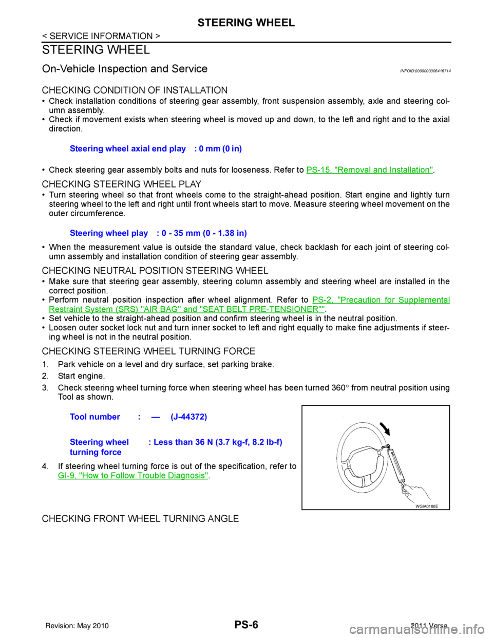
CHECKING STEERING WHEEL TURNING FORCE
1. Park vehicle on a level and dry surface, set parking brake.
2. Start engine.
3. Check steering wheel turning force when steering wheel has been turned 360 ° from neutral position using
Tool as shown.
4. If steering wheel turning force is out of the specification, refer to GI-9, "
How to Follow Trouble Diagnosis".
CHECKING FRONT WHEEL TURNING ANGLE
Steering wheel axial end play : 0 mm (0 in)
Steering wheel play : 0 - 35 mm (0 - 1.38 in)
Tool number : — (J-44372)
Steering wheel
turning force : Less than 36 N (3.7 kg-f, 8.2 lb-f)
WGIA0180E
Revision: May 2010
2011 Versa
Page 3565 of 3787
RSU-12
< SERVICE INFORMATION >
REAR SUSPENSION BEAM
REAR SUSPENSION BEAM
Removal and InstallationINFOID:0000000005931090
REMOVAL
1. Remove wheel and tire using power tool.
2. Separate parking brake rear cable from rear drum brake and rear suspension beam. Refer to PB-5, "
On-
Vehicle Service".
3. Remove wheel sensor and wheel sensor harness from wheel hub and bearing assembly and rear suspen-
sion beam. Refer to BRC-33, "
Removal and Installation".
4. Remove lock plate and separate brake tube from brake hose. Refer to BR-12, "
Rear Brake Tube and Hose".
5. Remove wheel hub and bearing assembly and back plate. Refer to RAX-6, "
On-Vehicle Inspection and Service".
6. Set jack under rear suspension beam.
7. Remove coil spring (left/right). Refer to RSU-11, "
Removal and
Installation".
8. Remove bolts between body and rear suspension beam bracket. Refer to RSU-8, "
Component".
9. Gradually lower the jack, and then remove rear suspension beam from vehicle.
10. Remove the rear suspension beam bracket bolt and nut, and then remove rear suspension beam bracket
from rear suspension beam. Refer to RSU-8, "
Component".
11. Remove brake tube protector from rear suspension beam.
INSPECTION AFTER REMOVAL
Check components for deformation, cracks, and other damage, and replace if necessary.
INSTALLATION
Installation is in the reverse order of removal.
• For tightening torque, refer to RSU-8, "
Component".
• Refill with new brake fluid and bleed air. Refer to BR-9, "
Bleeding Brake System".
• Tighten wheel nuts to specification. Refer to WT-7, "
Adjustment".
• Check the following after finishing work.
- Parking brake operation (stroke): Refer to PB-5, "
On-Vehicle Service".
- Wheel sensor harness for proper connection: Refer to BRC-33, "
Removal and Installation".
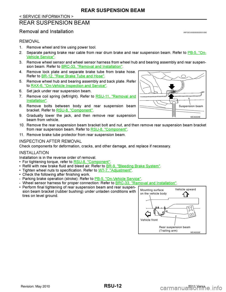
• Perform final tightening of rear suspension beam and rear suspen-
sion beam bracket (rubber bushing) under unladen conditions with
tires on level ground.
MEIA0029E
MEIA0030E
Revision: May 2010 2011 Versa