air suspension NISSAN TIIDA 2011 Service User Guide
[x] Cancel search | Manufacturer: NISSAN, Model Year: 2011, Model line: TIIDA, Model: NISSAN TIIDA 2011Pages: 3787, PDF Size: 78.35 MB
Page 3173 of 3787

MA-2
OIL FILTER : Removal and Installation ..................33
SPARK PLUG ........................................................ ...34
SPARK PLUG : Component ...................................34
SPARK PLUG : Removal and Installation ..............35
EVAP VAPOR LINES ............................................. ...36
EVAP VAPOR LINES : Checking EVAP Vapor
Line .........................................................................
36
CHASSIS AND BODY MAINTENANCE ............37
EXHAUST SYSTEM ............................................... ...37
EXHAUST SYSTEM : Checking Exhaust System
HR16DE .............................................................. ...
37
EXHAUST SYSTEM : Checking Exhaust System
MR18DE .............................................................. ...
37
CVT FLUID ............................................................. ...37
CVT FLUID : Checking CVT Fluid ..........................37
CVT FLUID : Changing CVT Fluid ..........................38
CLUTCH FLUID ..................................................... ...39
CLUTCH FLUID : Air Bleeding Procedure ..............39
M/T OIL ................................................................... ...40
M/T OIL : Draining (RS5F91R) ...............................40
M/T OIL : Refilling (RS5F91R) ................................41
M/T OIL : Inspection (RS5F91R) ............................41
M/T OIL : Changing M/T Oil (RS6F94R) .................41
M/T OIL : Checking M/T Oil (RS6FF94R) ...............42
A/T FLUID .............................................................. ...42
A/T FLUID : Checking A/T Fluid .............................42
A/T FLUID : Changing A/T Fluid .............................43
WHEELS ................................................................. ...43
WHEELS : Adjustment ............................................43
BRAKE FLUID LEVEL AND LEAKS ..................... ...45
BRAKE FLUID LEVEL AND LEAKS : On Board In-
spection ...................................................................
45
BRAKE FLUID LEVEL AND LEAKS : Drain and
Refill ........................................................................
45
BRAKE LINES AND CABLES ............................... ...46
BRAKE LINES AND CABLES : Checking Brake
Line and Cables ................................................... ...
46
DISC BRAKE .......................................................... ...46
DISC BRAKE : On Board Inspection ......................46
DRUM BRAKE ....................................................... ...46
DRUM BRAKE : Inspection .....................................46
AXLE AND SUSPENSION PARTS ........................ ...47
AXLE AND SUSPENSION PARTS : Axle and
Suspension Parts ................................................. ...
47
DRIVE SHAFT ........................................................ ...48
DRIVE SHAFT : Drive Shaft ...................................48
LOCKS, HINGES AND HOOD LATCH .................. ...48
LOCKS, HINGES AND HOOD LATCH : Lubricat-
ing Locks, Hinges and Hood Latch .........................
49
SEAT BELT, BUCKLES, RETRACTORS, AN-
CHORS AND ADJUSTERS ................................... ...
49
SEAT BELT, BUCKLES, RETRACTORS, AN-
CHORS AND ADJUSTERS : Checking Seat
Belts, Buckles, Retractors, Anchors and Adjusters
...
49
Revision: May 2010 2011 Versa
Page 3183 of 3787
![NISSAN TIIDA 2011 Service User Guide MA-12
< SERVICE INFORMATION >
PERIODIC MAINTENANCE
Abbreviations: R = Replace. I = Inspect. Correct or replace if necessary. [ ]: At the mileage intervals only
(1) After 60,000 miles (96,000 km) or 48](/img/5/57396/w960_57396-3182.png "NISSAN TIIDA 2011 Service User Guide MA-12
< SERVICE INFORMATION >
PERIODIC MAINTENANCE
Abbreviations: R = Replace. I = Inspect. Correct or replace if necessary. [ ]: At the mileage intervals only
(1) After 60,000 miles (96,000 km) or 48")
MA-12
< SERVICE INFORMATION >
PERIODIC MAINTENANCE
Abbreviations: R = Replace. I = Inspect. Correct or replace if necessary. [ ]: At the mileage intervals only
(1) After 60,000 miles (96,000 km) or 48 months, inspect every 15,000 miles (24,000 km) or 12 months. Replace the drive belt if found
damaged or if the auto belt tensioner reading reaches the maximum limit.
(2) Maintenance-free item. For service procedures, refer to the FL section.
(3) First replacement interval is 105,000 miles (168,000 km) or 84 months. After first replacement, replace every 75,000 miles (120,000
km) or 60 months. Use only Genuine NISSAN long life Antifreeze/Coolant (blue) or equivalent with proper mixture ratio of 50% an ti-
freeze and 50% demineralized or distilled water. Mixing any other type of coolant or the use of non-distilled water will reduce the life
expectancy of the factory fill coolant.
(4) Periodic maintenance is not required. However, if valve noise increases, inspect valve clearance.
Maintenance items and intervals with “*” are recommended by NISSAN for reliab le vehicle operation. The owner need not perform such
maintenance in order to maintain the emission warranty or manufacturer recall liability. Other maintenance items and intervals are
required.
Chassis and Body Maintenance
Abbreviations: R = Replace. I = Inspec t. Correct or replace if necessary. .
MAINTENANCE OPERATION MAINTENANCE INTERVAL
Reference
Section - Page
or - Content Ti- tle
Perform at number of miles,
kilometers or months, which-
ever comes first. Miles x
1,000
(km x
1,000)
Months 7.5
(12) 6 15
(24) 12 22.5
(36) 18 30
(48) 24 37.5
(60) 30 45
(72) 36 52.5
(84) 42 60
(96) 48
Drive belt NOTE (1) I*EM-13
(HR)
EM-132
(MR)
Air cleaner filter [R][R]EM-16
(HR)
EM-136
(MR)
EVAP vapor lines I*I*MA-25
(HR)
MA-36
(MR)
Fuel lines I*I*FL-5
Fuel filter NOTE (2) —
Engine coolant* NOTE (3) CO-11
(HR)
CO-36
(MR)
Engine oil RR R RRRRR LU-8
(HR)
LU-18
(MR)
Engine oil filter (Use genuine
oil filter or equivalent.) RR R RRRRR LU-9
(HR)
LU-20
(MR)
Spark plugs (Iridium/plati-
num - tipped type) Replace every 105,000 miles (168,000 km) EM-17
(HR)
EM-151
(MR)
Intake and exhaust valve
clearance* NOTE (4)
EM-114
(HR)
EM-230
(MR)
MAINTENANCE OPERATION MAINTENANCE INTERVAL
Reference Sec-
tion - Page or -
Content Title
Perform at number of miles, kilo-
meters or months, whichever
comes first. Miles x 1,000
(km x 1,000)
Months 7.5
(12)
6 15
(24)
12 22.5
(36)
18 30
(48)
24 37.5
(60)
30 45
(72)
36 52.5
(84)
42 60
(96)
48
B ra ke lin e s & cab le s IIII MA-46
Brake pads, rotors, drums & lin-
ings IIII
MA-46
MA-46
Manual transaxle oil or automatic
transaxle fluid IIIIMT-11
(RS5F91R)
MT-54
(RS6F94R)
AT- 1 7
(A/T)
C VT flu id NO TE (1) IIII CVT-15
(RE0F08B)
Steering gear & linkage, axle &
suspension parts II
PS-15
, MA-47
Tire rotation NOTE (2) WT-7
Revision: May 2010 2011 Versa
Page 3218 of 3787

CHASSIS AND BODY MAINTENANCEMA-47
< SERVICE INFORMATION >
C
DE
F
G H
I
J
K
M A
B
MA
N
O P
Check lining thickness.
Drum Inner Diameter Inspection
Check inner diameter of brake drum.
Measurement area: lining contact surface (center)
Wheel Cylinder Leakage Inspection
• Check wheel cylinder for brake fluid leakage.
• Check for wear, damage, and looseness. If any non-standard con- dition is found, replace it.
Other Inspections
Check the following:
• Inside of the drum for excessive wear, damage, and cracks.
• Lining for excessive wear, damage, and peeling.
• Shoe sliding surface for excessive wear and damage.
• Return spring for sagging.
• Check back plate for damage, cracks, and deformation. Replace back plate as necessary.
Replace applicable part as necessary.
AXLE AND SUSPENSION PARTS
AXLE AND SUSPENSION PARTS : Axle and Suspension PartsINFOID:0000000005931184
Check front and rear axle and suspension parts for excessive play,
cracks, wear or other damage.
• Shake each wheel to check for excessive play.
• Check wheel bearings for smooth operation.
• Check axle and suspension nuts and bolts for looseness.
• Check strut (shock absorber) for oil leakage or other damage.
• Check suspension ball joint for grease leakage and ball joint dust
cover for cracks or other damage. Standard thickness (A) : Refer to
BR-42,
"Rear Drum Brake"
Repair limit thickness (A) : Refer toBR-42,
"Rear Drum Brake"
SBR021A
Standard inner diameter : Refer toBR-42, "Rear
Drum Brake"
Repair limit inner diameter : Refer toBR-42, "Rear
Drum Brake"
SBR022A
WFIA0528E
SMA525A
Revision: May 2010 2011 Versa
Page 3499 of 3787
NOISE, VIBRATION AND HARSHNESS (NVH) TROUBLESHOOTINGPS-5
< SERVICE INFORMATION >
C
DE
F
H I
J
K L
M A
B
PS
N
O P
NOISE, VIBRATION AND HARSHN ESS (NVH) TROUBLESHOOTING
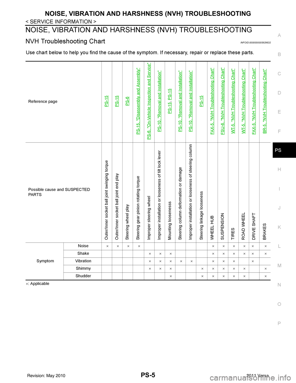
NVH Troubleshooting ChartINFOID:0000000005929632
Use chart below to help you find the cause of the symptom. If necessary, repair or replace these parts.
×: ApplicableReference page
PS-15PS-15PS-6
PS-15, "
Disassembly and Assembly
"
PS-6, "
On-Vehicle Inspection and Service
"
PS-10, "
Removal and Installation
"
PS-15
,
PS-15
PS-10, "
Removal and Installation
"
PS-10, "
Removal and Installation
"
PS-15
FAX-5, "
NVH Troubleshooting Chart
"
FSU-6, "
NVH Troubleshooting Chart
"
WT-5, "
NVH Troubleshooting Chart
"
WT-5, "
NVH Troubleshooting Chart
"
FAX-5, "
NVH Troubleshooting Chart
"
BR-5, "
NVH Troubleshooting Chart
"
Possible cause and SUSPECTED
PA R T S
Outer/Inner socket ball joint swinging torque
Outer/Inner socket ball joint end play
Steering wheel play
Steering gear pinion rotating torque
Improper steering wheel
Improper installation or looseness of tilt lock lever
Mounting loosenesss
Steering column deformation or damage
Improper installation or looseness of steering column
Steering linkage looseness
WHEEL HUB
SUSPENSION
TIRES
ROAD WHEEL
DRIVE SHAFT
BRAKES
Symptom Noise
××× × ××××× ×
Shake ×××××××× ×
Vibration ××××× ××× ×
Shimmy ×××× ×××× ×
Shudder ×× ×××× ×
Revision: May 2010 2011 Versa
Page 3500 of 3787
PS-6
< SERVICE INFORMATION >
STEERING WHEEL
STEERING WHEEL
On-Vehicle Inspection and ServiceINFOID:0000000006416714
CHECKING CONDITION OF INSTALLATION
• Check installation conditions of steering gear assembly, front suspension assembly, axle and steering col-
umn assembly.
• Check if movement exists when steering wheel is mo ved up and down, to the left and right and to the axial
direction.
• Check steering gear assembly bolts and nuts for looseness. Refer to PS-15, "
Removal and Installation".
CHECKING STEERING WHEEL PLAY
• Turn steering wheel so that front wheels come to the straight-ahead position. Start engine and lightly turn
steering wheel to the left and right until front wheels start to move. Measure steering wheel movement on the
outer circumference.
• When the measurement value is outside the standard val ue, check backlash for each joint of steering col-
umn assembly and installation condition of steering gear assembly.
CHECKING NEUTRAL POSITION STEERING WHEEL
• Make sure that steering gear assembly, steering column assembly and steering wheel are installed in the correct position.
• Perform neutral position inspection after wheel alignment. Refer to PS-2, "
Precaution for Supplemental
Restraint System (SRS) "AIR BAG" and "SEAT BELT PRE-TENSIONER"".
• Set vehicle to the straight-ahead position and c onfirm steering wheel is in the neutral position.
• Loosen outer socket lock nut and turn inner socket to left and right equally to make fine adjustments if steer-
ing wheel is not in the neutral position.
CHECKING STEERING WHEEL TURNING FORCE
1. Park vehicle on a level and dry surface, set parking brake.
2. Start engine.
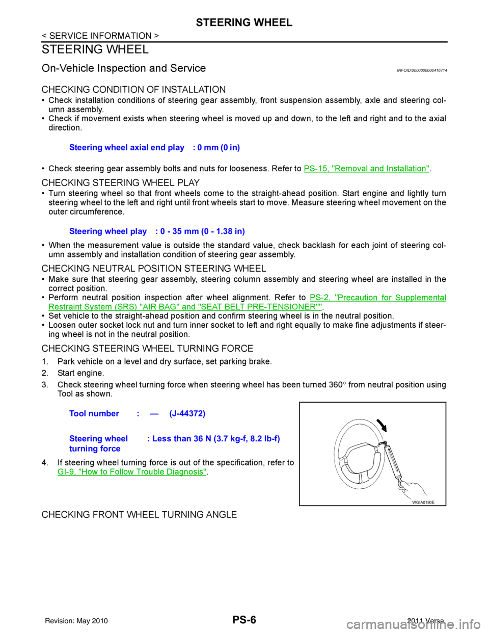
3. Check steering wheel turning force when steering wheel has been turned 360 ° from neutral position using
Tool as shown.
4. If steering wheel turning force is out of the specification, refer to GI-9, "
How to Follow Trouble Diagnosis".
CHECKING FRONT WHEEL TURNING ANGLE
Steering wheel axial end play : 0 mm (0 in)
Steering wheel play : 0 - 35 mm (0 - 1.38 in)
Tool number : — (J-44372)
Steering wheel
turning force : Less than 36 N (3.7 kg-f, 8.2 lb-f)
WGIA0180E
Revision: May 2010
2011 Versa
Page 3520 of 3787
NOISE, VIBRATION AND HARSHNESS (NVH) TROUBLESHOOTINGRAX-5
< SERVICE INFORMATION >
CEF
G H
I
J
K L
M A
B
RAX
N
O P
NOISE, VIBRATION AND HARSHN ESS (NVH) TROUBLESHOOTING
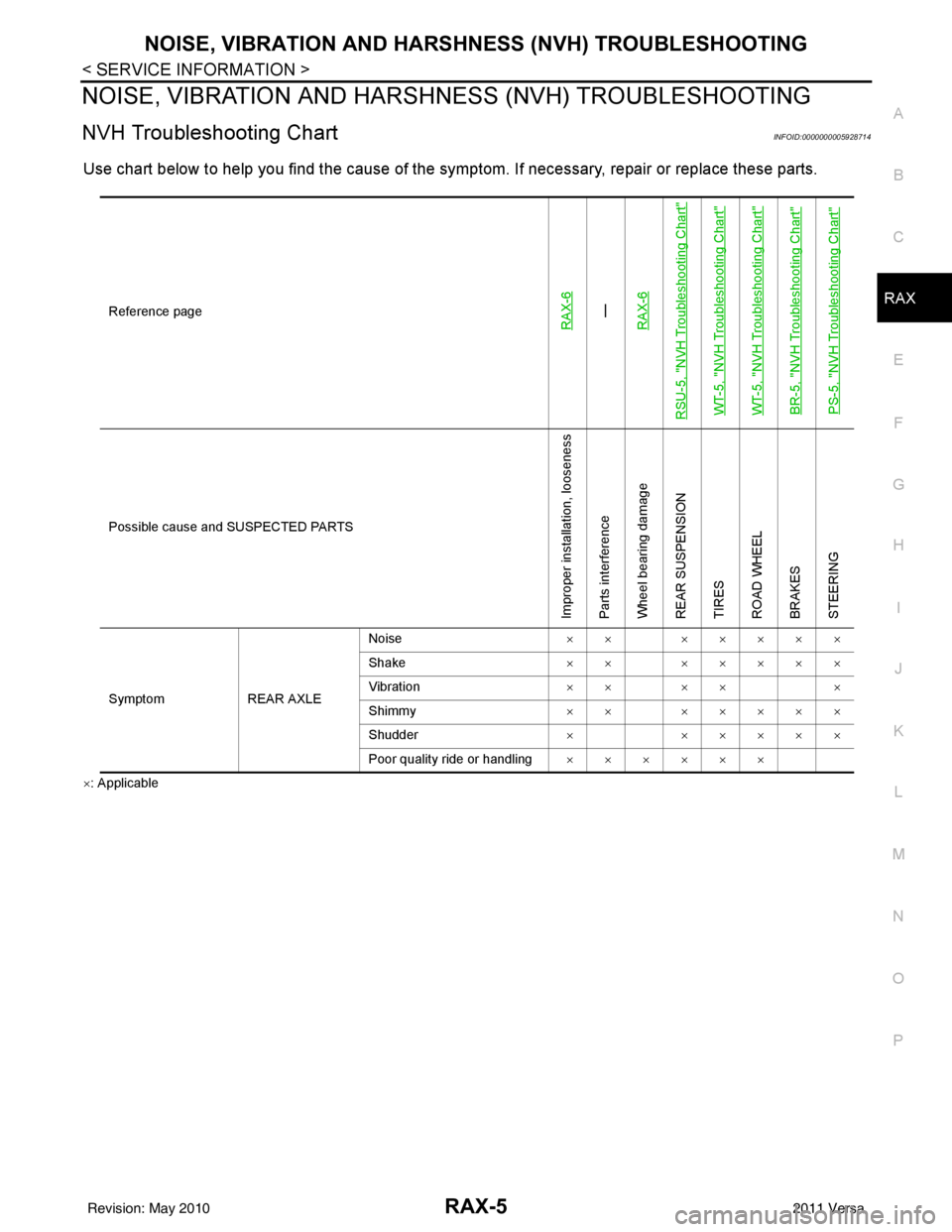
NVH Troubleshooting ChartINFOID:0000000005928714
Use chart below to help you find the cause of the symptom. If necessary, repair or replace these parts.
×: Applicable Reference page
RAX-6—
RAX-6
RSU-5, "
NVH Troubleshooting Chart
"
WT-5, "
NVH Troubleshooting Chart
"
WT-5, "
NVH Troubleshooting Chart
"
BR-5, "
NVH Troubleshooting Chart
"
PS-5, "
NVH Troubleshooting Chart
"
Possible cause and SUSPECTED PARTS
Improper installation, looseness
Parts interference
Wheel bearing damage
REAR SUSPENSION
TIRES
ROAD WHEEL
BRAKES
STEERING
Symptom REAR AXLENoise
×× ×××××
Shake ×× ×××××
Vibration ×× ×× ×
Shimmy ×× ×××××
Shudder ××××××
Poor quality ride or handling ××××××
Revision: May 2010 2011 Versa
Page 3554 of 3787

RSU-1
SUSPENSION
C
DF
G H
I
J
K L
M
SECTION RSU
A
B
RSU
N
O PCONTENTS
REAR SUSPENSION
SERVICE INFORMATION .. ..........................2
PRECAUTIONS .............................................. .....2
Precaution for Supplemental Restraint System
(SRS) "AIR BAG" and "SEAT BELT PRE-TEN-
SIONER" ............................................................. ......
2
Precaution Necessary for Steering Wheel Rota-
tion After Battery Disconnect ............................... ......
2
Precaution for Rear Suspension ......................... ......3
PREPARATION .............................................. .....4
Commercial Service Tool .................................... ......4
NOISE, VIBRATION AND HARSHNESS
(NVH) TROUBLESHOOTING .............................
5
NVH Troubleshooting Chart ................................ ......5
REAR SUSPENSION ASSEMBLY .....................6
On-Vehicle Inspection and Service ..................... .....6
Wheel AlignmentInspection ......................................6
Component ...............................................................8
SHOCK ABSORBER .........................................9
Removal and Installation ..........................................9
Disposal ...................................................................10
COIL SPRING ...................................................11
Removal and Installation .........................................11
REAR SUSPENSION BEAM ............................12
Removal and Installation ..................................... ....12
SERVICE DATA AND SPECIFICATIONS
(SDS) .................................................................
13
Wheel Alignment (Unladen*) ...................................13
Wheelarch Height (Unladen*) ..................................13
Revision: May 2010 2011 Versa
Page 3556 of 3787

PRECAUTIONSRSU-3
< SERVICE INFORMATION >
C
DF
G H
I
J
K L
M A
B
RSU
N
O P
5. When the repair work is completed, return the ignition switch to the ″LOCK ″ position before connecting
the battery cables. (At this time, the steering lock mechanism will engage.)
6. Perform a self-diagnosis check of al l control units using CONSULT-III.
Precaution for Rear SuspensionINFOID:0000000005931081
• When installing the rubber bushings, the final tightening must be done under unladen condition and with the
tires on level ground. Oil will shorten the life of the rubber bushings, so wipe off any spilled oil immediately.
• Unladen condition means the fuel tank, engine coolant and lubricants are at the full specification. The spare
tire, jack, hand tools, and mats are in their designated positions.
• After installing suspension components, check the wheel alignment.
• Caulking nuts are not reusable. Always use new caulking nuts for installation. New caulking nuts are pre- oiled, do not apply any additional lubrication.
Revision: May 2010 2011 Versa
Page 3558 of 3787
NOISE, VIBRATION AND HARSHNESS (NVH) TROUBLESHOOTINGRSU-5
< SERVICE INFORMATION >
C
DF
G H
I
J
K L
M A
B
RSU
N
O P
NOISE, VIBRATION AND HARSHN ESS (NVH) TROUBLESHOOTING
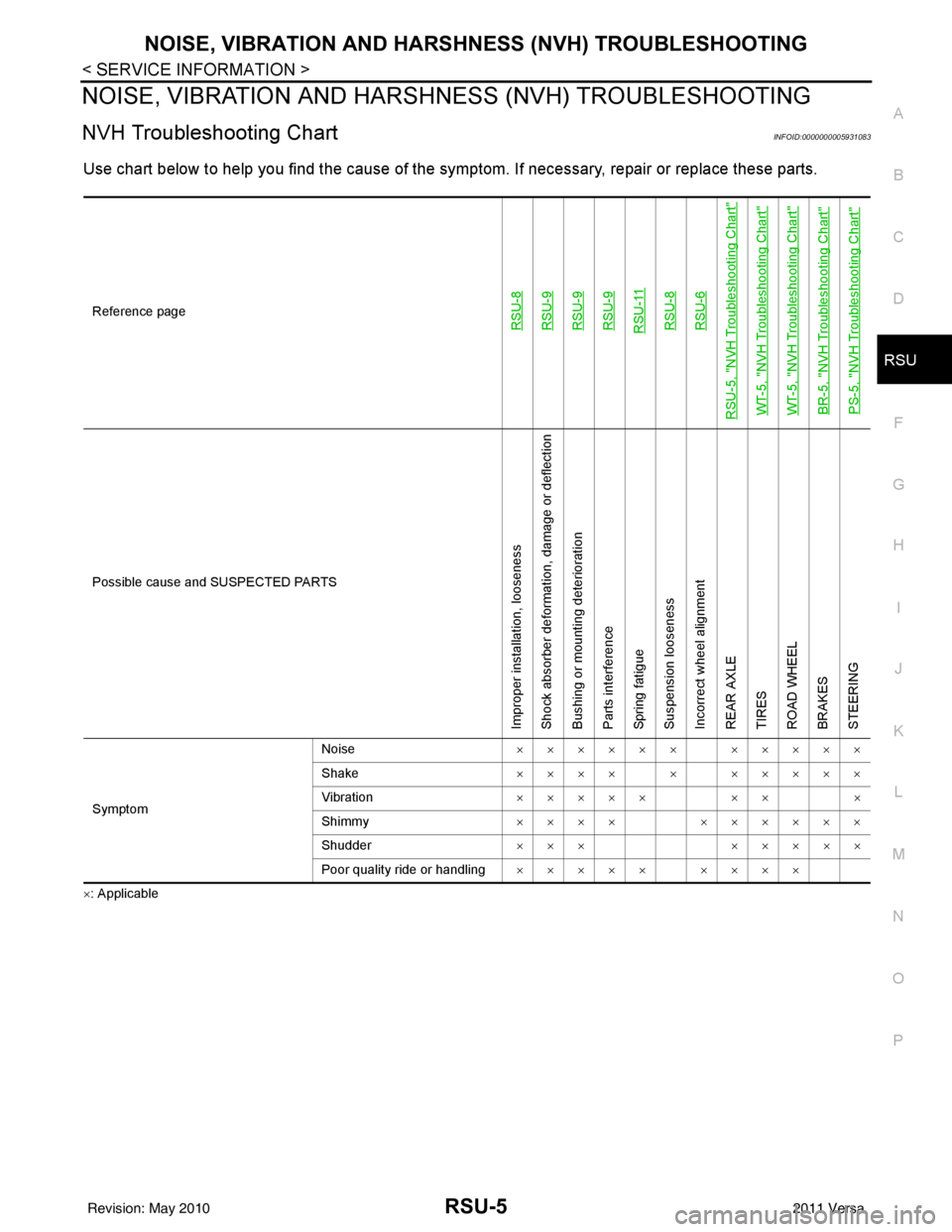
NVH Troubleshooting ChartINFOID:0000000005931083
Use chart below to help you find the cause of the symptom. If necessary, repair or replace these parts.
×: ApplicableReference page
RSU-8RSU-9RSU-9RSU-9RSU-11RSU-8RSU-6
RSU-5, "
NVH Troubleshooting Chart
"
WT-5, "
NVH Troubleshooting Chart
"
WT-5, "
NVH Troubleshooting Chart
"
BR-5, "
NVH Troubleshooting Chart
"
PS-5, "
NVH Troubleshooting Chart
"
Possible cause and SUSPECTED PARTS
Improper installation, looseness
Shock absorber deformation, damage or deflection
Bushing or mounting deterioration
Parts interference
Spring fatigue
Suspension looseness
Incorrect wheel alignment
REAR AXLE
TIRES
ROAD WHEEL
BRAKES
STEERING
Symptom
Noise
×××××× ×××××
Shake ×××× × ×××××
Vibration ××××× ×× ×
Shimmy ×××× ××××××
Shudder ××× ×××××
Poor quality ride or handling ××××× ××××
Revision: May 2010 2011 Versa
Page 3559 of 3787
RSU-6
< SERVICE INFORMATION >
REAR SUSPENSION ASSEMBLY
REAR SUSPENSION ASSEMBLY
On-Vehicle Inspection and ServiceINFOID:0000000005931084
Make sure the mounting conditions (looseness, backlash) of each component and component conditions
(wear, damage) are within specifications.
SHOCK ABSORBER INSPECTION
Check shock absorber for oil leakage, damage and replace it if necessary.
Wheel AlignmentInspectionINFOID:0000000005931085
DESCRIPTION
Measure wheel alignment under unladen conditions.
NOTE:
“Unladen conditions” means that fuel, engine coolant, and lubricant are full. Spare tire, jack, hand tools and
mats are in designated positions.
PRELIMINARY
Check the following:
1. Tires for improper air pressure and wear.
2. Road wheels for runout. Refer to WT-6
.
3. Wheel bearing axial end play. Refer to RAX-6, "
On-Vehicle Inspection and Service" .
4. Shock absorber operation.
5. Each mounting part of suspension for looseness and deformation.
6. Rear suspension beam for cracks, deformation, and other damage.
7. Vehicle height (posture).
GENERAL INFORMATION AND RECOMMENDATIONS
1. A Four-Wheel Thrust Alignment should be performed. • This type of alignment is recommended for any NISSAN vehicle.
• The four-wheel “thrust” process helps ensure that the vehicle is properly aligned and the steering wheel
is centered.
• The alignment machine itself should be ca pable of accepting any NISSAN vehicle.
• The alignment machine should be checked to ensure that it is level.
2. Make sure the alignment machine is properly calibrated. • Your alignment machine should be regularly calibrated in order to give correct information.
• Check with the manufacturer of your specific al ignment machine for their recommended Service/Cali-
bration Schedule.
THE ALIGNMENT PROCESS
IMPORTANT: Use only the alignment specifications listed in this Service Manual. Refer to RSU-13, "Wheel
Alignment (Unladen*)" .
1. When displaying the alignment settings, many alignment machines use “indicators”: (Green/red, plus or minus, Go/No Go). Do NOT use these indicators.
• The alignment specifications programmed into your alignment machine that operate these indicators may not be correct.
• This may result in an ERROR.
2. Some newer alignment machines are equipped with an optional “Rolling Compensation” method to “com- pensate” the sensors (alignment targets or head units). Do NOT use this “Rolling Compensation”
method.
• Use the “Jacking Compensation” method. After inst alling the alignment targets or head units, raise the
vehicle and rotate the wheels 1/2 turn both ways.
• See Instructions in the alignment machine you are using for more information.
CAMBER INSPECTION
Revision: May 2010 2011 Versa