air suspension NISSAN TIIDA 2011 Service Repair Manual
[x] Cancel search | Manufacturer: NISSAN, Model Year: 2011, Model line: TIIDA, Model: NISSAN TIIDA 2011Pages: 3787, PDF Size: 78.35 MB
Page 1 of 3787
-1
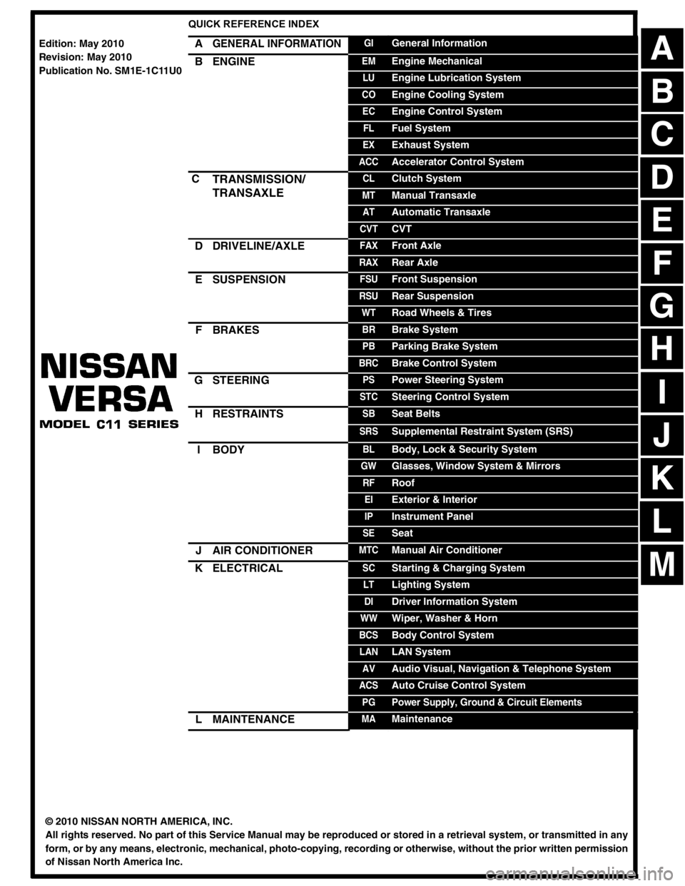
QUICK REFERENCE INDEX
AGENERAL INFORMATIONGIGeneral Information
BENGINEEMEngine Mechanical
LUEngine Lubrication System
COEngine Cooling System
ECEngine Control System
FLFuel System
EXExhaust System
ACCAccelerator Control System
CTRANSMISSION/
TRANSAXLECLClutch System
MTManual Transaxle
ATAutomatic Transaxle
CVTCVT
DDRIVELINE/AXLEFAXFront Axle
RAXRear Axle
ESUSPENSIONFSUFront Suspension
RSURear Suspension
WTRoad Wheels & Tires
FBRAKESBRBrake System
PBParking Brake System
BRCBrake Control System
GSTEERINGPSPower Steering System
STCSteering Control System
HRESTRAINTSSBSeat Belts
SRSSupplemental Restraint System (SRS)
IBODYBLBody, Lock & Security System
GWGlasses, Window System & Mirrors
RFRoof
EIExterior & Interior
IPInstrument Panel
SESeat
JAIR CONDITIONERMTCManual Air Conditioner
KELECTRICALSCStarting & Charging System
LTLighting System
DIDriver Information System
WWWiper, Washer & Horn
BCSBody Control System
LANLAN System
AVAudio Visual, Navigation & Telephone System
ACSAuto Cruise Control System
PGPower Supply, Ground & Circuit Elements
LMAINTENANCEMAMaintenance
Edition: May 2010
Revision: May 2010
Publication No. SM1E-1C11U0
B
D
© 2010 NISSAN NORTH AMERICA, INC.
All rights reserved. No part of this Service Manual may be reproduced or stored in a retrieval system, or transmitted in any
form, or by any means, electronic, mechanical, photo-copying, recording or otherwise, without the prior written permission
of Nissan North America Inc.
A
C
E
F
G
H
I
J
K
L
M
Page 778 of 3787

BL-268
< SERVICE INFORMATION >
BODY REPAIR
4. Front pillar inner reinforcement (RH&LH)
5. Lower dash reinforcement
6. 4th crossmember (RH&LH)
7. Front side member rear extension (RH&LH)
8. 3rd crossmember (RH&LH)
9. Front seat outer rear bracket (RH&LH)
10. Front seat inner rear bracket (RH&LH)
11. 2nd crossmember (RH&LH)
12. Front seat outer front bracket (RH&LH)
13. Front seat inner front bracket (RH&LH)
14. Fender bracket (RH&LH)
15. Strut housing assembly RH
16. Cowl top side upper (RH&LH)
17. Front strut housing (RH&LH)
18. Upper torque rod reinforcement
19. Closing plate assembly RH
20. Engine mount reinforcement
21. Strut tower front reinforcement RH
22. Front hoodledge lower RH
23. Frame bracket outer (RH&LH)
24. Front bumper support bracket (RH&LH)
25. Closing plate (RH&LH)
26. Front suspension rear bracket (RH&LH)
27. Front side member outrigger (RH&LH)
28. Front side member assembly (RH&LH)
29. Front side member (RH&LH)
30. Frame bracket (RH&LH)
31. Closing plate assembly LH
32. Hoodledge connector (RH&LH)
33. Radiator core side support (RH&LH)
34. Radiator core support upper (RH&LH)
35. Hoodledge upper (RH&LH)
36. Hoodledge reinforcement assembly (RH&LH)
37. Dash side (RH&LH)
38. Dash side assembly (RH& LH)
39. Front floor reinforcement (RH&LH)
40. Front floor front (RH&LH)
41. Front floor center
42. Rear seat crossmember
43. Rear center crossmember
44. Rear seat upper crossmember
45. Rear side member (RH&LH)
46. Sill inner extension (RH&LH)
47. Rear side member extension (RH&LH)
48. Rear side member assembly (RH & LH)
49. Rear floor front
50. Rear floor front assembly
51. Rear floor side (RH&LH)
52. Rear floor rear
Revision: May 20102011 Versa
Page 831 of 3787
BODY REPAIRBL-321
< SERVICE INFORMATION >
C
DE
F
G H
J
K L
M A
B
BL
N
O P
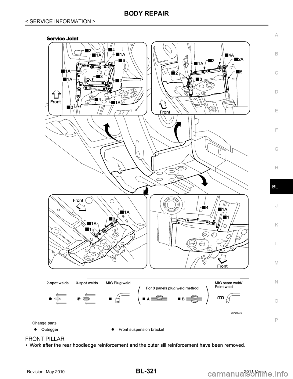
FRONT PILLAR
• Work after the rear hoodledge reinforcement and the outer sill reinforcement have been removed.
Change parts �z Outrigger �zFront suspension bracket
LIIA2897E
Revision: May 2010 2011 Versa
Page 852 of 3787
NOISE, VIBRATION AND HARSHNESS (NVH) TROUBLESHOOTINGBR-5
< SERVICE INFORMATION >
C
DE
G H
I
J
K L
M A
B
BR
N
O P
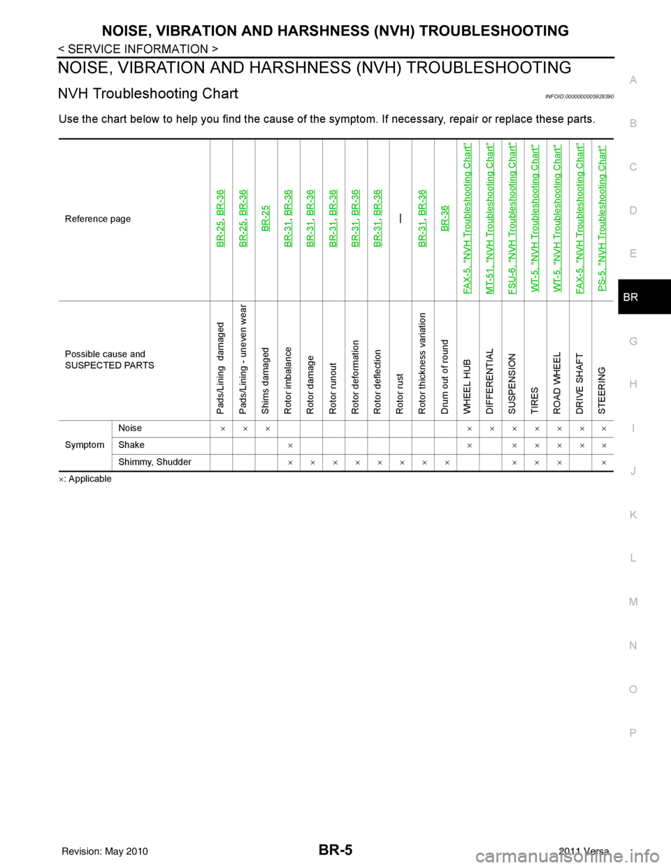
NOISE, VIBRATION AND HARSHN ESS (NVH) TROUBLESHOOTING
NVH Troubleshooting ChartINFOID:0000000005928390
Use the chart below to help you find t he cause of the symptom. If necessary, repair or replace these parts.
×: ApplicableReference page
BR-25
,
BR-36
BR-25
, BR-36BR-25
BR-31
, BR-36
BR-31
, BR-36
BR-31
, BR-36
BR-31
, BR-36
BR-31
, BR-36—
BR-31, BR-36BR-36
FAX-5, "
NVH Troubleshooting Chart
"
MT-51, "
NVH Troubleshooting Chart
"
FSU-6, "
NVH Troubleshooting Chart
"
WT-5, "
NVH Troubleshooting Chart
"
WT-5, "
NVH Troubleshooting Chart
"
FAX-5, "
NVH Troubleshooting Chart
"
PS-5, "
NVH Troubleshooting Chart
"
Possible cause and
SUSPECTED PARTS
Pads/Lining damaged
Pads/Lining - uneven wear
Shims damaged
Rotor imbalance
Rotor damage
Rotor runout
Rotor deformation
Rotor deflection
Rotor rust
Rotor thickness variation
Drum out of round
WHEEL HUB
DIFFERENTIAL
SUSPENSION
TIRES
ROAD WHEEL
DRIVE SHAFT
STEERING
Symptom Noise
××× ×××××××
Shake × × ×××××
Shimmy, Shudder ×××××××× ××× ×
Revision: May 2010 2011 Versa
Page 928 of 3787
![NISSAN TIIDA 2011 Service Repair Manual PRECAUTIONSBRC-39
< SERVICE INFORMATION > [VDC/TCS/ABS]
C
D
E
G H
I
J
K L
M A
B
BRC
N
O P
5. When the repair work is completed, re-connect both battery cables. With the brake pedal released, turn the NISSAN TIIDA 2011 Service Repair Manual PRECAUTIONSBRC-39
< SERVICE INFORMATION > [VDC/TCS/ABS]
C
D
E
G H
I
J
K L
M A
B
BRC
N
O P
5. When the repair work is completed, re-connect both battery cables. With the brake pedal released, turn the](/img/5/57396/w960_57396-927.png)
PRECAUTIONSBRC-39
< SERVICE INFORMATION > [VDC/TCS/ABS]
C
D
E
G H
I
J
K L
M A
B
BRC
N
O P
5. When the repair work is completed, re-connect both battery cables. With the brake pedal released, turn the push-button ignition switch from ACC position to ON position, then to LOCK position. (The steering
wheel will lock when the push-button ignition switch is turned to LOCK position.)
6. Perform self-diagnosis check of a ll control units using CONSULT-III.
Precaution for Brake SystemINFOID:0000000005928462
CAUTION:
• Refer to MA-14, "
Fluids and Lubricants" for recommended brake fluid.
• Never reuse drained brake fluid.
• Be careful not to splash brake fluid on painted areas; it may cause paint damage. If brake fluid is
splashed on painted areas, wash it away with water immediately.
• To clean or wash all parts of master cylin der and disc brake caliper, use clean brake fluid.
• Never use mineral oils such as gasoline or kerosen e. They will ruin rubber parts of the hydraulic sys-
tem.
• Use flare nut wrench when removing and installing brake tube.
• If a brake fluid leak is found, the part must be disassembled
without fail. Then it has to be replaced with a new one if a
defect exists.
• Turn the ignition switch OFF and remove the connector of the
ABS actuator and electric unit (con trol unit) or the battery ter-
minal before performing the work.
• Always torque brake lines when installing.
• Burnish the brake contact surf aces after refinishing or replac-
ing rotors, after replacing pads, or if a soft pedal occurs at
very low mileage.
Refer to BR-34, "
Brake Burnishing Procedure".
WARNING:
• Clean brake pads and shoes with a waste cl oth, then wipe with a dust collector.
Precaution for Brake ControlINFOID:0000000005928463
• During ABS operation, the brake pedal may vibrate lightly and a mechanical noise may be heard. This is
normal.
• Just after starting vehicle, the brake pedal may vibrate or a motor operating noise may be heard from engine
compartment. This is a normal status of operation check.
• Stopping distance may be longer than that of vehicles without ABS when vehicle drives on rough, gravel, or snow-covered (fresh, deep snow) roads.
• When an error is indicated by ABS or another warning lamp, collect all necessary information from customer (what symptoms are present under what conditions) and check for simple causes before starting diagnosis.
Besides electrical system inspection, check boos ter operation, brake fluid level, and fluid leaks.
• If incorrect tire sizes or types are installed on the vehicle or brake pads are not Genuine NISSAN parts, stop-
ping distance or steering stability may deteriorate.
• If there is a radio, antenna or related wiring near control module, ABS function may have a malfunction or
error.
• If aftermarket parts (car stereo, CD player, etc.) have been installed, check for incidents such as harness pinches, open circuits or improper wiring.
• If the following components are replaced with non-genuine components or modified, the VDC OFF indicator lamp and SLIP indicator lamp may turn on or the VDC system may not operate properly. Components
related to suspension (shock absorbers, struts, springs , bushings, etc.), tires, wheels (exclude specified
size), components related to brake system (pads, roto rs, calipers, etc.), components related to engine (muf-
fler, ECM, etc.), components related to body reinforcement (roll bar, tower bar, etc.).
• Driving with broken or excessively worn suspensi on components, tires or brake system components may
cause the VDC OFF indicator lamp and the SLIP indicator lamp to turn on, and the VDC system may not
operate properly.
• When the TCS or VDC is activated by sudden acceleration or sudden turn, some noise may occur. The noise is a result of the normal operation of the TCS and VDC.
• When driving on roads which have extreme slopes (such as mountainous roads) or high banks (such as sharp curves on a freeway), the VDC may not operate no rmally, or the VDC warning lamp and the SLIP indi-
cator lamp may turn on. This is not a problem if normal operation can be resumed after restarting the engine.
SBR686C
Revision: May 2010 2011 Versa
Page 2647 of 3787
NOISE, VIBRATION AND HARSHNESS (NVH) TROUBLESHOOTINGFAX-5
< SERVICE INFORMATION >
CEF
G H
I
J
K L
M A
B
FA X
N
O P
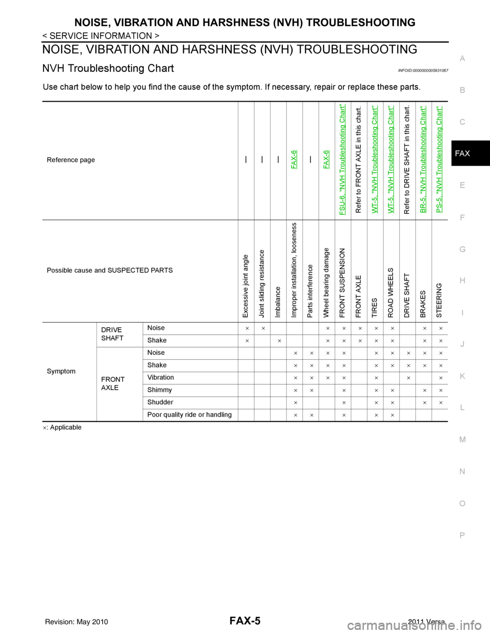
NOISE, VIBRATION AND HARSHN ESS (NVH) TROUBLESHOOTING
NVH Troubleshooting ChartINFOID:0000000005931067
Use chart below to help you find the cause of the symptom. If necessary, repair or replace these parts.
×: ApplicableReference page
—
—
—
FAX-6—
FAX-6
FSU-6, "
NVH Troubleshooting Chart
"
Refer to FRONT AXLE in this chart.
WT-5, "
NVH Troubleshooting Chart
"
WT-5, "
NVH Troubleshooting Chart
"
Refer to DRIVE SHAFT in this chart. BR-5, "
NVH Troubleshooting Chart
"
PS-5, "
NVH Troubleshooting Chart
"
Possible cause and SUSPECTED PARTS
Excessive joint angle
Joint sliding resistance
Imbalance
Improper installation, looseness
Parts interference
Wheel bearing damage
FRONT SUSPENSION
FRONT AXLE
TIRES
ROAD WHEELS
DRIVE SHAFT
BRAKES
STEERING
SymptomDRIVE
SHAFT
Noise
××××××× ××
Shake × × ××××× ××
FRONT
AXLE Noise
×××× ×××××
Shake ×××× ×××××
Vibration ×××××××
Shimmy ×××××××
Shudder × × ×× ××
Poor quality ride or handling ×××××
Revision: May 2010 2011 Versa
Page 2686 of 3787

FSU-1
SUSPENSION
C
DF
G H
I
J
K L
M
SECTION FSU
A
B
FSU
N
O PCONTENTS
FRONT SUSPENSION
SERVICE INFORMATION .. ..........................2
PRECAUTIONS .............................................. .....2
Precaution for Supplemental Restraint System
(SRS) "AIR BAG" and "SEAT BELT PRE-TEN-
SIONER" ............................................................. ......
2
Precaution Necessary for Steering Wheel Rota-
tion After Battery Disconnect ............................... ......
2
Precaution for Procedure without Cowl Top Cover ......3
General Precautions .................................................3
PREPARATION ...................................................4
Special Service Tool ........................................... ......4
Commercial Service Tool ..........................................5
NOISE, VIBRATION AND HARSHNESS
(NVH) TROUBLESHOOTING .............................
6
NVH Troubleshooting Chart ................................ ......6
FRONT SUSPENSION ASSEMBLY ...................7
On-Vehicle Inspection and Service ..................... ......7
Wheel Alignment Inspection .....................................7
Component .......................................................... ....10
Removal and Installation .........................................11
COIL SPRING AND STRUT ..............................12
Removal and Installation .........................................12
Disposal ...................................................................12
Disassembly and Assembly .....................................13
TRANSVERSE LINK .........................................15
Removal and Installation .........................................15
STABILIZER BAR .............................................16
Removal and Installation .........................................16
SERVICE DATA AND SPECIFICATIONS
(SDS) .................................................................
17
Wheel Alignment (Unladen*) ...................................17
Ball Joint ..................................................................18
Wheelarch Height (Unladen*) ..................................19
Revision: May 2010 2011 Versa
Page 2688 of 3787
PRECAUTIONSFSU-3
< SERVICE INFORMATION >
C
DF
G H
I
J
K L
M A
B
FSU
N
O P
5. When the repair work is completed, return the ignition switch to the ″LOCK ″ position before connecting
the battery cables. (At this time, the steering lock mechanism will engage).
6. Perform a self-diagnosis check of al l control units using CONSULT-III.
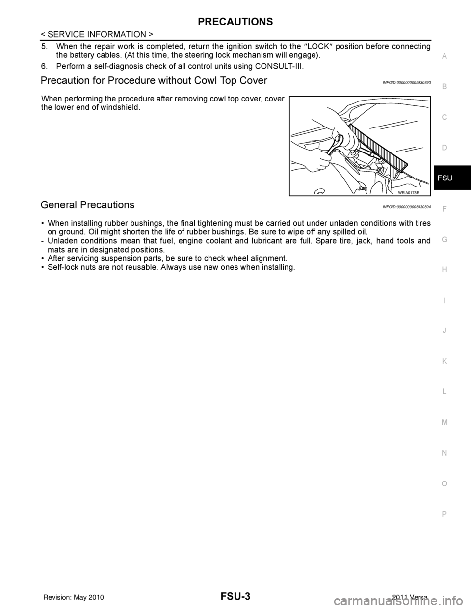
Precaution for Procedure without Cowl Top CoverINFOID:0000000005930893
When performing the procedure after removing cowl top cover, cover
the lower end of windshield.
General PrecautionsINFOID:0000000005930894
• When installing rubber bushings, the final tightening mu st be carried out under unladen conditions with tires
on ground. Oil might shorten the life of rubber bushings. Be sure to wipe off any spilled oil.
- Unladen conditions mean that fuel, engine coolant and l ubricant are full. Spare tire, jack, hand tools and
mats are in designated positions.
• After servicing suspension parts, be sure to check wheel alignment.
• Self-lock nuts are not reusable. A lways use new ones when installing.
WEIA0178E
Revision: May 2010 2011 Versa
Page 2691 of 3787
FSU-6
< SERVICE INFORMATION >
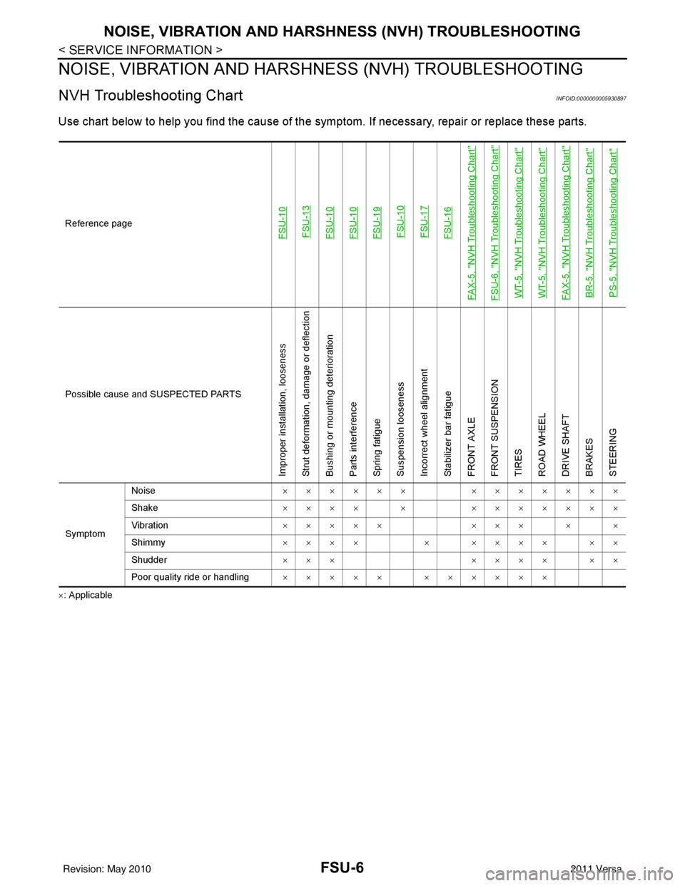
NOISE, VIBRATION AND HARSHNESS (NVH) TROUBLESHOOTING
NOISE, VIBRATION AND HARSHNESS (NVH) TROUBLESHOOTING
NVH Troubleshooting ChartINFOID:0000000005930897
Use chart below to help you find the cause of the symp tom. If necessary, repair or replace these parts.
×: ApplicableReference page
FSU-10
FSU-13FSU-10FSU-10FSU-19 FSU-10 FSU-17FSU-16
FAX-5, "
NVH Troubleshooting Chart
"
FSU-6, "
NVH Troubleshooting Chart
"
WT-5, "
NVH Troubleshooting Chart
"
WT-5, "
NVH Troubleshooting Chart
"
FAX-5, "
NVH Troubleshooting Chart
"
BR-5, "
NVH Troubleshooting Chart
"
PS-5, "
NVH Troubleshooting Chart
"
Possible cause an d SUSPECTED PARTS
Improper installation, looseness
Strut deformation, damage or deflection
Bushing or mounting deterioration
Parts interference
Spring fatigue
Suspension looseness
Incorrect wheel alignment
Stabilizer bar fatigue
FRONT AXLE
FRONT SUSPENSION
TIRES
ROAD WHEEL
DRIVE SHAFT
BRAKES
STEERING
SymptomNoise
×××××× ×××××××
Shake ×××× × ×××××××
Vibration ××××× ××× × ×
Shimmy ×××× × ×××× ××
Shudder ××× ×××× ××
Poor quality ride or handling ××××× ××××××
Revision: May 2010 2011 Versa
Page 2692 of 3787
FRONT SUSPENSION ASSEMBLYFSU-7
< SERVICE INFORMATION >
C
DF
G H
I
J
K L
M A
B
FSU
N
O P
FRONT SUSPENSION ASSEMBLY
On-Vehicle Inspection and ServiceINFOID:0000000005930898
Make sure the mounting conditions (looseness, back lash) of each component and component conditions
(wear, damage) are normal.
INSPECTION OF LOWER BALL JOINT END PLAY
1. Set front wheels in a straight-ahead position. Do not depress brake pedal.
2. Place an iron bar or similar tool between transverse link and steering knuckle.
3. Measure axial end play by prying it up and down.
CAUTION:
Be careful not to damage ball joint boot. Do not damage the installation position by applying
excessive force.
STRUT INSPECTION
Check for oil leakage, damage and replace as necessary.
Wheel Alignment InspectionINFOID:0000000005930899
PRELIMINARY INSPECTION
WARNING:
Always adjust the alignment with the vehicle on a flat surface.
NOTE:
If alignment is out of specification, inspect and replace any damaged or worn rear suspension parts before
making any adjustments.
1. Check and adjust the wheel alignment with the vehicle under unladen conditions. “Unladen conditions”
means that the fuel, coolant, and lubricant are full; and that the spare tire, jack, hand tools and mats are in
their designated positions.
2. Check the tires for incorrect air pressure and excessive wear.
3. Check the wheels for run out and damage. Refer to WT-6, "
Inspection".
4. Check the wheel bearing axial end play. Refer to FAX-6, "
On-Vehicle Inspection and Service".
5. Check the shock absorbers for leaks or damage.
6. Check each mounting point of the suspension components for any excessive looseness or damage.
7. Check each link, arm, and the suspension member for any damage.
8. Check the vehicle height. Refer to FSU-19, "
Wheelarch Height (Unladen*)".
GENERAL INFORMATION AND RECOMMENDATIONS
1. A Four-Wheel Thrust Alignment should be performed.
• This type of alignment is re commended for any NISSAN vehicle.
• The four-wheel “thrust” process helps ensure that the vehicle is properly aligned and the steering wheel
is centered.
• The alignment machine itself should be ca pable of accepting any NISSAN vehicle.
• The alignment machine should be checked to ensure that it is level.
2. Make sure the alignment machine is properly calibrated. • Your alignment machine should be regularly calibrated in order to give correct information.
• Check with the manufacturer of your specific a lignment machine for their recommended Service/Cali-
bration Schedule.
THE ALIGNMENT PROCESS
IMPORTANT: Use only the alignment specifications listed in this Service Manual. Refer to FSU-17, "Wheel
Alignment (Unladen*)".
1. When displaying the alignment settings, many alignm ent machines use “indicators”: (Green/red, plus or
minus, Go/No Go). Do NOT use these indicators.
• The alignment specifications programmed into your alignment machine that operate these indicators may not be correct.Axial end play : 0 mm (0 in)
Revision: May 2010
2011 Versa