Engine warning NISSAN TIIDA 2011 Service Service Manual
[x] Cancel search | Manufacturer: NISSAN, Model Year: 2011, Model line: TIIDA, Model: NISSAN TIIDA 2011Pages: 3787, PDF Size: 78.35 MB
Page 1036 of 3787
![NISSAN TIIDA 2011 Service Service Manual CO-36
< SERVICE INFORMATION >[MR18DE]
ENGINE COOLANT
ENGINE COOLANT
InspectionINFOID:0000000005930806
LEVEL CHECK
• Check if the reservoir tank engine coolant level is within the “MIN”
to “MAX](/img/5/57396/w960_57396-1035.png "NISSAN TIIDA 2011 Service Service Manual CO-36
< SERVICE INFORMATION >[MR18DE]
ENGINE COOLANT
ENGINE COOLANT
InspectionINFOID:0000000005930806
LEVEL CHECK
• Check if the reservoir tank engine coolant level is within the “MIN”
to “MAX")
CO-36
< SERVICE INFORMATION >[MR18DE]
ENGINE COOLANT
ENGINE COOLANT
InspectionINFOID:0000000005930806
LEVEL CHECK
• Check if the reservoir tank engine coolant level is within the “MIN”
to “MAX” range when engine is cool.
• Adjust the engine coolant level as necessary.
CHECKING COOLING SYSTEM FOR LEAKS
To check for leaks, apply pressure to the cooling system using suit-
able tool and Tool.
WARNING:
Never remove the radiator cap wh en the engine is hot. Serious
burns could occur from high pressure coolant escaping from
the radiator.
CAUTION:
Higher pressure than specified may cause radiator damage.
Changing Engine CoolantINFOID:0000000005930807
WARNING:
• To avoid being scalded, do not change engine coolant when engine is hot.
• Wrap a thick cloth around radiator cap and carefully remove the cap. First, turn the cap a quarter of a
turn to release built-up pressure. Then turn the cap all the way.
CAUTION:
• Do not spill engine coolant on drive belt.
DRAINING ENGINE COOLANT
1. Open radiator drain plug (1) at the bottom of radiator, and then
remove radiator cap.
• Front
When draining all of engine coolant in the system, open
water drain plug on cylinder block. Refer to EM-203
.
CAUTION:
• Perform this step when engine is cold.
• Do not spill engine coolant on drive belt.
2. Remove reservoir tank as necessary, and drain engine coolant and clean reservoir tank before installing. Refer to CO-40, "
Component".
3. Check drained engine coolant for contaminants such as rust, corrosion or discoloration. If contaminated, flush the engine cooling system.
SMA412B
Tool number : EG17650301 (J-33984-A)
Testing pressure : 157 kPa (1.6 kg/cm
2, 23 psi)
WBIA0568E
PBIC3799E
Revision: May 2010 2011 Versa
Page 1045 of 3787
![NISSAN TIIDA 2011 Service Service Manual WATER PUMPCO-45
< SERVICE INFORMATION > [MR18DE]
C
D
E
F
G H
I
J
K L
M A
CO
NP
O
WATER PUMP
ComponentINFOID:0000000005930816
Removal and InstallationINFOID:0000000005930817
WARNING:
Never remove the r](/img/5/57396/w960_57396-1044.png "NISSAN TIIDA 2011 Service Service Manual WATER PUMPCO-45
< SERVICE INFORMATION > [MR18DE]
C
D
E
F
G H
I
J
K L
M A
CO
NP
O
WATER PUMP
ComponentINFOID:0000000005930816
Removal and InstallationINFOID:0000000005930817
WARNING:
Never remove the r")
WATER PUMPCO-45
< SERVICE INFORMATION > [MR18DE]
C
D
E
F
G H
I
J
K L
M A
CO
NP
O
WATER PUMP
ComponentINFOID:0000000005930816
Removal and InstallationINFOID:0000000005930817
WARNING:
Never remove the radiator cap when the engine is
hot. Serious burns could occur from high pressure
engine coolant escaping from the radiator.
REMOVAL
1. Disconnect battery negative terminal. Refer to SC-7, "Removal and Installation".
2. Remove reservoir tank. Refer to CO-40, "
Component".
3. Drain engine coolant from radiator. Refer to CO-36, "
Changing Engine Coolant".
CAUTION:
Perform this step when the engine is cold.
4. Remove front fender protector (RH). Refer to EI-26, "
Removal and Installation".
5. Remove drive belt. Refer to EM-132, "
Removal and Installation".
6. Remove generator. Refer to SC-25, "
Removal and Installation".
7. Remove radiator hose (lower). Refer to CO-40, "
Component".
8. Remove water pump. CAUTION:
• Handle water pump vane so that it does not contact any other parts.
• Water pump cannot be disassembled and should be replaced as a unit.
INSPECTION AFTER REMOVAL
• Visually check that there is no significant dirt or rusting on water
pump body and vane (A).
• Make sure that there is no looseness in vane shaft, and that it turns smoothly when rotated by hand.
• Replace water pump, if necessary.
1. Gasket 2. Water pump
PBIC3921E
PBIC3313J
Revision: May 2010 2011 Versa
Page 1062 of 3787
![NISSAN TIIDA 2011 Service Service Manual PRECAUTIONSCVT-7
< SERVICE INFORMATION > [RE0F08B]
D
E
F
G H
I
J
K L
M A
B
CVT
N
O P
PRECAUTIONS
Precaution for Supplemental Restraint System (SRS) "AIR BAG" and "SEAT BELT
PRE-TENSIONER"
INFOID:000](/img/5/57396/w960_57396-1061.png "NISSAN TIIDA 2011 Service Service Manual PRECAUTIONSCVT-7
< SERVICE INFORMATION > [RE0F08B]
D
E
F
G H
I
J
K L
M A
B
CVT
N
O P
PRECAUTIONS
Precaution for Supplemental Restraint System (SRS) \"AIR BAG\" and \"SEAT BELT
PRE-TENSIONER\"
INFOID:000")
PRECAUTIONSCVT-7
< SERVICE INFORMATION > [RE0F08B]
D
E
F
G H
I
J
K L
M A
B
CVT
N
O P
PRECAUTIONS
Precaution for Supplemental Restraint System (SRS) "AIR BAG" and "SEAT BELT
PRE-TENSIONER"
INFOID:0000000006414971
The Supplemental Restraint System such as “AIR BAG” and “SEAT BELT PRE-TENSIONER”, used along
with a front seat belt, helps to reduce the risk or severi ty of injury to the driver and front passenger for certain
types of collision. This system includes seat belt switch inputs and dual stage front air bag modules. The SRS
system uses the seat belt switches to determine the front air bag deployment, and may only deploy one front
air bag, depending on the severity of a collision and w hether the front occupants are belted or unbelted.
Information necessary to service the system safely is included in the SRS and SB section of this Service Man-
ual.
WARNING:
• To avoid rendering the SRS inoper ative, which could increase the risk of personal injury or death in
the event of a collision which would result in air bag inflation, all maintenance must be performed by
an authorized NISSAN/INFINITI dealer.
• Improper maintenance, including in correct removal and installation of the SRS can lead to personal
injury caused by unintentional act ivation of the system. For removal of Spiral Cable and Air Bag
Module, see the SRS section.
• Do not use electrical test equipm ent on any circuit related to the SRS unless instructed to in this
Service Manual. SRS wiring harnesses can be identi fied by yellow and/or orange harnesses or har-
ness connectors.
PRECAUTIONS WHEN USING POWER TOOLS (AIR OR ELECTRIC) AND HAMMERS
WARNING:
• When working near the Airbag Diagnosis Sensor Un it or other Airbag System sensors with the Igni-
tion ON or engine running, DO NOT use air or el ectric power tools or strike near the sensor(s) with a
hammer. Heavy vibration could activate the sensor( s) and deploy the air bag(s), possibly causing
serious injury.
• When using air or electric power tools or hammers, always switch the Ignition OFF, disconnect the battery, and wait at least 3 minutes before performing any service.
Precaution Necessary for Steering Wheel Rotation After Battery Disconnect
INFOID:0000000005928721
NOTE:
• This Procedure is applied only to models with Intelligent Key system and NVIS /IVIS (NISSAN/INFINITI
VEHICLE IMMOBILIZER SYSTEM - NATS).
• Remove and install all control units after disconnecti ng both battery cables with the ignition knob in the
″ LOCK ″ position.
• Always use CONSULT-III to perform self-diagnosis as a part of each function inspection after finishing work.
If DTC is detected, perform trouble diagnosis according to self-diagnostic results.
For models equipped with the Intelligent Key system and NVIS/IVIS, an electrically controlled steering lock
mechanism is adopted on the key cylinder.
For this reason, if the battery is disconnected or if the battery is discharged, the steering wheel will lock and
steering wheel rotation will become impossible.
If steering wheel rotation is required when battery power is interrupted, follow the procedure below before
starting the repair operation.
OPERATION PROCEDURE
1. Connect both battery cables. NOTE:
Supply power using jumper cables if battery is discharged.
2. Use the Intelligent Key or mechanical key to turn the ignition switch to the ″ACC ″ position. At this time, the
steering lock will be released.
3. Disconnect both battery cables. The steering lock will remain released and the steering wheel can be
rotated.
4. Perform the necessary repair operation.
5. When the repair work is completed, return the ignition switch to the ″LOCK ″ position before connecting
the battery cables. (At this time, the steering lock mechanism will engage.)
Revision: May 2010 2011 Versa
Page 1230 of 3787
![NISSAN TIIDA 2011 Service Service Manual CVT OIL WARMER SYSTEMCVT-175
< SERVICE INFORMATION > [RE0F08B]
D
E
F
G H
I
J
K L
M A
B
CVT
N
O P
CVT OIL WARMER SYSTEM
WATER HOSE
WATER HOSE : Exploded ViewINFOID:0000000006068646
WATER HOSE : Removal](/img/5/57396/w960_57396-1229.png "NISSAN TIIDA 2011 Service Service Manual CVT OIL WARMER SYSTEMCVT-175
< SERVICE INFORMATION > [RE0F08B]
D
E
F
G H
I
J
K L
M A
B
CVT
N
O P
CVT OIL WARMER SYSTEM
WATER HOSE
WATER HOSE : Exploded ViewINFOID:0000000006068646
WATER HOSE : Removal")
CVT OIL WARMER SYSTEMCVT-175
< SERVICE INFORMATION > [RE0F08B]
D
E
F
G H
I
J
K L
M A
B
CVT
N
O P
CVT OIL WARMER SYSTEM
WATER HOSE
WATER HOSE : Exploded ViewINFOID:0000000006068646
WATER HOSE : Removal and InstallationINFOID:0000000006068647
REMOVAL
WARNING:
Never remove the radiator cap when the engine is hot. Serious burns could occur from high pressure
coolant escaping from the radiator.
CAUTION:
Perform this step engine is cold.
1. Remove air duct (inlet). Refer to EM-135, "
Component".
2. Remove hose clamps, and remove CVT water hose A.
3. Remove hose clamps, and remove CVT water hose B.
4. Remove hose clamps, and remove CVT water hose C.
5. Remove CVT water tube.
INSTALLATION
Installation is in the reverse order of removal.
1. Hose clamp 2. CVT water hose C3. CVT water tube
4. CVT water hose B 5. Transaxle assembly6. CVT oil warmer
7. CVT water hose A
A. Water pump B. Water inlet-outlet
Refer to GI-8, "
Component" for symbols in the figure.
JSDIA1290GB
Revision: May 2010 2011 Versa
Page 1234 of 3787
![NISSAN TIIDA 2011 Service Service Manual CVT OIL WARMER SYSTEMCVT-179
< SERVICE INFORMATION > [RE0F08B]
D
E
F
G H
I
J
K L
M A
B
CVT
N
O P
CVT FLUID COOLER HOSE : InspectionINFOID:0000000006068651
INSPECTION AFTER INSTALLATION
Check for CVT f](/img/5/57396/w960_57396-1233.png "NISSAN TIIDA 2011 Service Service Manual CVT OIL WARMER SYSTEMCVT-179
< SERVICE INFORMATION > [RE0F08B]
D
E
F
G H
I
J
K L
M A
B
CVT
N
O P
CVT FLUID COOLER HOSE : InspectionINFOID:0000000006068651
INSPECTION AFTER INSTALLATION
Check for CVT f")
CVT OIL WARMER SYSTEMCVT-179
< SERVICE INFORMATION > [RE0F08B]
D
E
F
G H
I
J
K L
M A
B
CVT
N
O P
CVT FLUID COOLER HOSE : InspectionINFOID:0000000006068651
INSPECTION AFTER INSTALLATION
Check for CVT fluid leakage and check CVT fluid level. Refer to CVT-14, "Checking CVT Fluid".
CVT OIL WARMER
CVT OIL WARMER : Exploded ViewINFOID:0000000006068652
CVT OIL WARMER : Removal and InstallationINFOID:0000000006068653
REMOVAL
WARNING:
Never remove the radiator cap when the engine is hot. Serious burns could occur from high pressure
coolant escaping from the radiator.
CAUTION:
Perform this step engine is cold.
1. Remove CVT water hose from CVT oil warmer. Refer to CVT-175, "
WATER HOSE : Exploded View".
2. Remove CVT fluid cooler hose from CVT oil warmer. Refer to CVT-177, "
CVT FLUID COOLER HOSE :
Exploded View".
3. Remove CVT oil warmer.
4. Remove bracket.
INSTALLATION
Installation is in the reverse order of removal.
CVT OIL WARMER : InspectionINFOID:0000000006068654
INSPECTION AFTER INSTALLATION
• Check for CVT fluid leakage and check CVT fluid level. Refer to CVT-14, "Checking CVT Fluid".
• Start and warm up the engine. Visually check that there is no leakage of engine coolant and CVT fluid.
1. CVT oil warmer2. Bracket3. Transaxle assembly
Refer to GI-8, "
Component" for symbols in the figure.
JPDIA0725GB
Revision: May 2010 2011 Versa
Page 1235 of 3787
![NISSAN TIIDA 2011 Service Service Manual CVT-180
< SERVICE INFORMATION >[RE0F08B]
TRANSAXLE ASSEMBLY
TRANSAXLE ASSEMBLY
Removal and InstallationINFOID:0000000005928976
COMPONENTS
REMOVAL
WARNING:
Never remove the radiator cap when the engine](/img/5/57396/w960_57396-1234.png "NISSAN TIIDA 2011 Service Service Manual CVT-180
< SERVICE INFORMATION >[RE0F08B]
TRANSAXLE ASSEMBLY
TRANSAXLE ASSEMBLY
Removal and InstallationINFOID:0000000005928976
COMPONENTS
REMOVAL
WARNING:
Never remove the radiator cap when the engine")
CVT-180
< SERVICE INFORMATION >[RE0F08B]
TRANSAXLE ASSEMBLY
TRANSAXLE ASSEMBLY
Removal and InstallationINFOID:0000000005928976
COMPONENTS
REMOVAL
WARNING:
Never remove the radiator cap when the engine is hot. Serious burns coul
d occur from high pressure
coolant escaping from the radiator.
CAUTION:
• Perform this step engine is cold.
• When replacing TCM and transaxle assembly as a set, replace transaxle assembly first and then replace TCM. Refer to CVT-8, "
Service After Replacing TCM and Transaxle Assembly".
1. Remove the engine and transaxle as an assembly. Refer to EM-197, "
Removal and Installation".
1. CVT fluid level gauge2. CVT fluid charging pipe 3. O-ring
4. Copper washer 5. Fluid cooler tube6. Transaxle assembly
7. Engine mounting bracket (LH) 8. Air breather hose A. Refer to "INSTALLATION".
WCIA0614E
Revision: May 2010 2011 Versa
Page 1240 of 3787

DI-1
ELECTRICAL
C
DE
F
G H
I
J
L
M
SECTION DI
A
B
DI
N
O P
CONTENTS
DRIVER INFORMATION SYSTEM
SERVICE INFORMATION .. ..........................2
PRECAUTION ................................................ .....2
Precaution for Supplemental Restraint System
(SRS) "AIR BAG" and "SEAT BELT PRE-TEN-
SIONER" ............................................................. ......
2
Precaution Necessary for Steering Wheel Rota-
tion After Battery Disconnect ............................... ......
2
COMBINATION METERS ...................................4
Component Parts and Harness Connector Loca-
tion ...................................................................... ......
4
System Description ...................................................4
Arrangement of Combination Meter ..........................6
Internal Circuit ...........................................................7
Wiring Diagram - METER - .......................................8
Combination Meter Harness Connector Terminal
Layout .....................................................................
10
Terminal and Reference Value for Combination
Meter .......................................................................
10
Self-Diagnosis Mode of Combination Meter ........ ....11
CONSULT-III Function (METER/M&A) ............... ....13
Trouble Diagnosis ...................................................14
Symptom Chart .......................................................15
Power Supply and Ground Circuit Inspection .........15
Vehicle Speed Signal Inspection .............................16
Engine Speed Signal Inspection .............................17
Fuel Level Sensor Signal Inspection .......................17
Fuel Gauge Fluctuates, Indicates Wrong Value, or
Varies ......................................................................
19
Fuel Gauge Does Not Move to Full-position ...........19
DTC [U1000] CAN Communication Circuit ......... ....19
Electrical Component Inspection .............................20
Removal and Installation .........................................20
WARNING LAMPS ......................................... ....21
Schematic ........................................................... ....21
Wiring Diagram - WARN - ................................... ....22
Oil Pressure Warning Lamp Stays Off (Ignition
Switch ON) .......................................................... ....
30
Oil Pressure Warning Lamp Does Not Turn Off
(Oil Pressure Is Normal) ...................................... ....
32
Component Inspection .............................................32
A/T INDICATOR ................................................34
System Description ..................................................34
Wiring Diagram - AT/IND - .......................................35
A/T Indicator Does Not Illuminate ............................36
CVT INDICATOR ...............................................38
System Description ..................................................38
Schematic ................................................................38
Wiring Diagram - CVTIND - .....................................39
CVT Indicator Does Not Illuminate ..........................41
WARNING CHIME .............................................43
Component Parts and Harness Connector Loca-
tion ....................................................................... ....
43
System Description ..................................................43
Wiring Diagram - CHIME - .......................................46
Terminal and Reference Value for BCM ..................47
CONSULT-III Function (B CM) .................................47
Trouble Diagnosis ................................................ ....48
Combination Meter Buzzer Circuit Inspection .........49
Front Door Switch LH Signal Inspection .............. ....50
Key Switch Signal Inspection (Without Intelligent
Key) ..................................................................... ....
51
Key Switch and Ignition Knob Switch Signal In-
spection (With Intelligent Key, When Mechanical
Key Is Used) ........................................................ ....
52
Lighting Switch Signal Inspection ............................54
Parking Brake Switch Signal Inspection ..................54
Electrical Component Inspection .............................55
Revision: May 2010 2011 Versa
Page 1241 of 3787

DI-2
< SERVICE INFORMATION >
PRECAUTION
SERVICE INFORMATION
PRECAUTION
Precaution for Supplemental Restraint System (SRS) "AIR BAG" and "SEAT BELT
PRE-TENSIONER"
INFOID:0000000006412029
The Supplemental Restraint System such as “A IR BAG” and “SEAT BELT PRE-TENSIONER”, used along
with a front seat belt, helps to reduce the risk or severity of injury to the driver and front passenger for certain
types of collision. This system includes seat belt switch inputs and dual stage front air bag modules. The SRS
system uses the seat belt switches to determine the front air bag deployment, and may only deploy one front
air bag, depending on the severity of a collision and w hether the front occupants are belted or unbelted.
Information necessary to service the system safely is included in the SRS and SB section of this Service Man-
ual.
WARNING:
• To avoid rendering the SRS inopera tive, which could increase the risk of personal injury or death in
the event of a collision which would result in air bag inflation, all maintenance must be performed by
an authorized NISSAN/INFINITI dealer.
• Improper maintenance, including in correct removal and installation of the SRS, can lead to personal
injury caused by unintent ional activation of the system. For re moval of Spiral Cable and Air Bag
Module, see the SRS section.
• Do not use electrical test equipmen t on any circuit related to the SRS unless instructed to in this
Service Manual. SRS wiring harn esses can be identified by yellow and/or orange harnesses or har-
ness connectors.
PRECAUTIONS WHEN USING POWER TOOLS (AIR OR ELECTRIC) AND HAMMERS
WARNING:
• When working near the Airbag Diagnosis Sensor Unit or other Airbag System sensors with the Igni-
tion ON or engine running, DO NOT use air or electri c power tools or strike near the sensor(s) with a
hammer. Heavy vibration could activate the sensor( s) and deploy the air bag(s), possibly causing
serious injury.
• When using air or electric power tools or hammers , always switch the Ignition OFF, disconnect the
battery, and wait at least 3 minu tes before performing any service.
Precaution Necessary for Steering W heel Rotation After Battery Disconnect
INFOID:0000000006412030
NOTE:
• This Procedure is applied only to models with Intelligent Key system and NATS (NISSAN ANTI-THEFT SYS-
TEM).
• Remove and install all control units after disconnecting both battery cables with the ignition knob in the
″LOCK ″ position.
• Always use CONSULT-III to perform self-diagnosis as a part of each function inspection after finishing work.
If DTC is detected, perform trouble diagnosis according to self-diagnostic results.
For models equipped with the Intelligent Key system and NATS, an electrically controlled steering lock mech-
anism is adopted on the key cylinder.
For this reason, if the battery is disconnected or if the battery is discharged, the steering wheel will lock and
steering wheel rotation will become impossible.
If steering wheel rotation is required when battery pow er is interrupted, follow the procedure below before
starting the repair operation.
OPERATION PROCEDURE
1. Connect both battery cables. NOTE:
Supply power using jumper cables if battery is discharged.
2. Use the Intelligent Key or mechanical key to turn the ignition switch to the ″ACC ″ position. At this time, the
steering lock will be released.
3. Disconnect both battery cables. The steering lock will remain released and the steering wheel can be rotated.
4. Perform the necessary repair operation.
Revision: May 2010 2011 Versa
Page 1250 of 3787
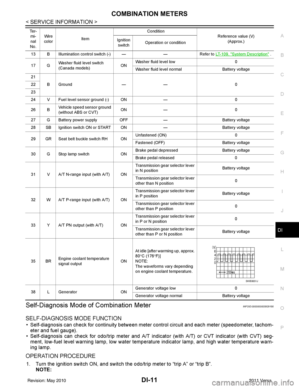
COMBINATION METERSDI-11
< SERVICE INFORMATION >
C
DE
F
G H
I
J
L
M A
B
DI
N
O P
Self-Diagnosis Mode of Combination MeterINFOID:0000000005929166
SELF-DIAGNOSIS MODE FUNCTION
• Self-diagnosis can check for continuity between meter control circuit and each meter (speedometer, tachom- eter and fuel gauge).
• Self-diagnosis can check for odo/trip meter and A/T indi cator (with A/T) or CVT indicator (with CVT) seg-
ment, low-fuel level warning lamp, low water temperature indicator lamp, and high water temperature warn-
ing lamp.
OPERATION PROCEDURE
1. Turn the ignition switch ON, and switch the odo/trip meter to “trip A” or “trip B”. NOTE:
13 B Illumination control switch (-) — —Refer to LT- 1 0 9 , "System Description" .
17 G Washer fluid level switch
(Canada models)
ONWasher fluid level low
0
Washer fluid level normal Battery voltage
21 BGround —— 0
22
23
24 V Fuel level sensor ground (-) ON —0
26 B Vehicle speed sensor ground
(without ABS or CVT) ON
— 0
27 G Battery power supply OFF— Battery voltage
28 SB Ignition switch ON or START ON —Battery voltage
29 GR Seat belt buckle switch RH ON Unfastened (ON)
0
Fastened (OFF) Battery voltage
30 G Stop lamp switch ONBrake pedal depressed
Battery voltage
Brake pedal released 0
31 V A/T N-range input (with A/T) ON Transmission gear selector lever
in N position
Battery voltage
Transmission gear selector lever
other than N position 0
32 W A/T P-range input (with A/T) ON Transmission gear selector lever
in P position
Battery voltage
Transmission gear selector lever
other than P position 0
33 Y A/T PN output (with A/T) ON Transmission gear selector lever
in P or N position
0
Transmission gear selector lever
other than P or N position Battery voltage
35 BR Engine coolant temperature
signal output
ONAt idle [after warming up, approx.
80
°C (176 °F)]
NOTE:
The waveforms vary depending
on engine coolant temperature.
38 L Generator ONGenerator voltage low
0
Generator voltage no rmal Battery voltage
Te r -
mi-
nal
No. Wire
color Item Condition
Reference value (V)
(Approx.)
Ignition
switch Operation or condition
SKIB3651J
Revision: May 2010
2011 Versa
Page 1252 of 3787

COMBINATION METERSDI-13
< SERVICE INFORMATION >
C
DE
F
G H
I
J
L
M A
B
DI
N
O P
CONSULT-III Function (METER/M&A)INFOID:0000000005929167
CONSULT-III can display each diagnostic item us ing the diagnostic test modes shown following.
SELF-DIAGNOSTIC RESULTS
Display Item List
NOTE:
“TIME” indicates the following.
• 0: Indicates that a malfunction is detected at present.
• 1-63: Indicates that a malfunction was detected in the past. (Displays number of ignition switch OFF → ON
cycles after malfunction is detected. Self-di agnostic result is erased when “63” is exceeded.)
DATA MONITOR
Display Item List
METER diagnosis mode Description
SELF-DIAG RESULTS Displays combination meter self-diagnosis results. DATA MONITOR Displays combination meter input/output data in real time.
CAN DIAG SUPPORT MNTR The result of transmit/receive diagnosis of CAN communication can be read.
CONSULT-III display MalfunctionReference page
CAN COMM CIRC [U1000] Malfunction is detected in CAN communication lines.
CAUTION:
Even when there is no malfuncti
on on CAN communication system, mal-
function may be misinterpreted when battery has low voltage (when main-
taining 7 - 8 V for about 2 seconds) or 10A fuse [No. 14, located in the fuse
block (J/B)] is removed. DI-19
VEHICLE SPEED CIRC [B2205]
Malfunction is detected when an erroneous speed signal is input.
CAUTION:
Even when there is no malfunction
on speed signal system, malfunctions
may be misinterpreted when battery has low voltage (when maintaining 7
- 8 V for about 2 seconds). DI-16
Display item [Unit]
MAIN
SIGNALS SELECTION
FROM MENU Contents
SPEED METER [km/h] XXThe value of vehicle speed signa
l, which is input from ABS ac-
tuator and electric unit (control unit).
SPEED OUTPUT [km/h] XXThe value of vehicle speed signal, which is transmitted to each
unit with CAN communication.
TACHO METER [rpm] XX The value of engine speed signal, which is input from ECM.
W TEMP METER [ °C] X XThe value of engine coolant temperature signal, which is input
from ECM.
FUEL METER [lit.] XXThe value, which processes a resistance signal from fuel
gauge.
DISTANCE [km] XXThe value, which is calculated by vehicle speed signal from
ABS actuator and electric unit (control unit), fuel gauge and fuel
consumption signal from ECM.
FUEL W/L [ON/OFF] XX Indicates [ON/OFF] condition of low-fuel warning lamp.
C-ENG W/L [ON/OFF] XIndicates [ON/OFF] condition of malfunction indicator lamp
(MIL).
AIR PRES W/L X Indicates [ON/OFF] condition of low tire pressure warning lamp.
SEAT BELT W/L X Indicates [ON/OFF] condition of seat belt warning lamp.
BUZZER [ON/OFF] XX Indicates [ON/OFF] condition of buzzer.
DOOR W/L [ON/OFF] X Indicates [ON/OFF] condition of door warning lamp.
HI-BEAM IND [ON/OFF] X Indicates [ON/OFF] condition of high beam indicator lamp.
Revision: May 2010 2011 Versa