Engine warning NISSAN TIIDA 2011 Service Workshop Manual
[x] Cancel search | Manufacturer: NISSAN, Model Year: 2011, Model line: TIIDA, Model: NISSAN TIIDA 2011Pages: 3787, PDF Size: 78.35 MB
Page 1254 of 3787
COMBINATION METERSDI-15
< SERVICE INFORMATION >
C
DE
F
G H
I
J
L
M A
B
DI
N
O P
YES >> GO TO 2.
NO >> Check power supply and ground circuit of combination meter. Refer to DI-15, "
Power Supply and
Ground Circuit Inspection" .
2.CHECK COMBINATION METER (CONSULT-III)
Select “METER/M&A” on CONSULT-II I and perform self-diagnosis of combination meter. Refer to DI-13,
"CONSULT-III Function (METER/M&A)" .
Self
-diagnostic results content
No malfunction detected>> Refer to DI-15, "Symptom Chart" .
Malfunction detected>> Refer to DI-13, "
CONSULT-III Function (METER/M&A)" .
Symptom ChartINFOID:0000000005929169
Power Supply and Gro und Circuit InspectionINFOID:0000000005929170
1.CHECK FUSE
Check for blown combination meter fuses.
OK or NG
OK >> GO TO 2.
NG >> Be sure to eliminate cause of malfunction before installing new fuse. Refer to PG-4
.
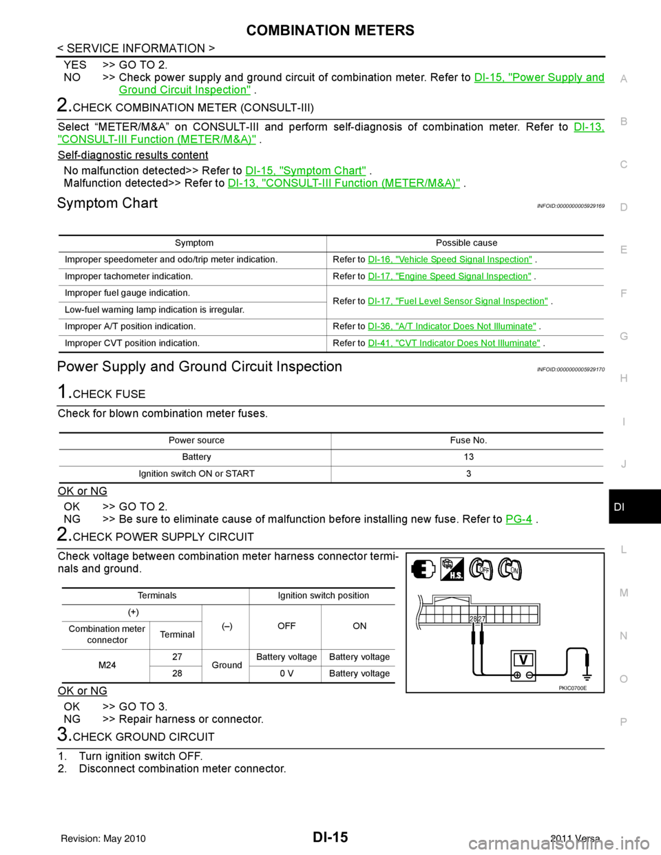
2.CHECK POWER SUPPLY CIRCUIT
Check voltage between combination meter harness connector termi-
nals and ground.
OK or NG
OK >> GO TO 3.
NG >> Repair harness or connector.
3.CHECK GROUND CIRCUIT
1. Turn ignition switch OFF.
2. Disconnect combination meter connector.
Symptom Possible cause
Improper speedometer and odo/trip meter indication. Refer to DI-16, "
Vehicle Speed Signal Inspection" .
Improper tachometer indication. Refer to DI-17, "
Engine Speed Signal Inspection" .
Improper fuel gauge indication. Refer to DI-17, "
Fuel Level Sensor Signal Inspection" .
Low-fuel warning lamp indication is irregular.
Improper A/T position indication. Refer to DI-36, "
A/T Indicator Does Not Illuminate" .
Improper CVT position indication. Refer to DI-41, "
CVT Indicator Does Not Illuminate" .
Power source Fuse No.
Battery 13
Ignition switch ON or START 3
TerminalsIgnition switch position
(+) (–) OFF ON
Combination meter
connector Te r m i n a l
M24 27
Ground Battery voltage Battery voltage
28 0 V Battery voltage
PKIC0700E
Revision: May 2010 2011 Versa
Page 1256 of 3787
COMBINATION METERSDI-17
< SERVICE INFORMATION >
C
DE
F
G H
I
J
L
M A
B
DI
N
O P
OK or NG
OK >> Check harness or connector between combination meter and vehicle speed sensor.
NG >> Replace vehicle speed sensor.
WITH CVT, WITHOUT ABS
1.CHECK COMBINATION METER INPUT SIGNAL
1. Start engine and select “M ETER/M&A” on CONSULT-III.
2. Using “SPEED METER” on “DATA MONITOR”, comp are the value of “DATA MONITOR” with speedome-
ter pointer of combination meter.
OK or NG
OK >> Perform TCM self-diagnosis. Refer to CVT-48, "CONSULT-III Function (TRANSMISSION)" .
NG >> Replace combination meter. Refer to IP-12, "
Removal and Installation" .
Engine Speed Signal InspectionINFOID:0000000005929172
Symptom: Improper tachometer indication.
1.CHECK COMBINATION METER INPUT SIGNAL
1. Start engine and select “M ETER/M&A” on CONSULT-III.
2. Using “TACHO METER” on “DATA MONITOR”, compare the value of “DATA MONITOR” with tachometer pointer of combination meter.
OK or NG
OK >> Perform ECM self-diagnosis. Refer to EC-612, "CONSULT-III Function (ENGINE)" (MR18DE) or
EC-106, "
CONSULT-III Function" (HR16DE).
NG >> Replace combination meter. Refer to IP-12, "
Removal and Installation" .
Fuel Level Sensor Signal InspectionINFOID:0000000005929173
Symptom:• Improper fuel gauge indication.
• Low-fuel warning lamp indication is irregular.
NOTE:
The following symptoms do not indicate a malfunction.
• Depending on vehicle position or driving circumstance, the fuel level in the tank shifts and the indication may fluctuate.
• If the vehicle is fueled with the ignition switch ON, the indication will update slowly.
• If the vehicle is tilted when the ignition switch is turned ON, fuel in the tank may flow to one direction result-
ing in a change of reading.
1.CHECK COMBINATION METER INPUT SIGNAL
1. Select “METER/M&A” on CONSULT-III.
2. Using “FUEL METER” on “DATA MONITOR”, compare the value of “DATA MONITOR” with fuel gauge pointer of combination meter.
Te r m i n a l s Resistance
value
(Approx.)
(+)
(–)
Component Terminal Component Terminal Ve h i c l e speed
sensor 1Vehicle
speed
sensor 22
50Ω
Fuel gauge pointer Reference value of data monitor [lit.]
Full Approx. 49
3/4 Approx. 34
1/2 Approx. 22
Revision: May 2010 2011 Versa
Page 1270 of 3787
WARNING LAMPSDI-31
< SERVICE INFORMATION >
C
DE
F
G H
I
J
L
M A
B
DI
N
O P
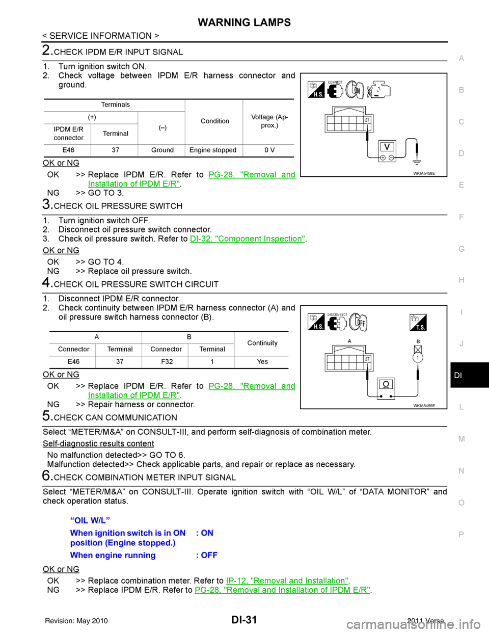
2.CHECK IPDM E/R INPUT SIGNAL
1. Turn ignition switch ON.
2. Check voltage between IPDM E/R harness connector and ground.
OK or NG
OK >> Replace IPDM E/R. Refer to PG-28, "Removal and
Installation of IPDM E/R".
NG >> GO TO 3.
3.CHECK OIL PRESSURE SWITCH
1. Turn ignition switch OFF.
2. Disconnect oil pressure switch connector.
3. Check oil pressure switch. Refer to DI-32, "
Component Inspection".
OK or NG
OK >> GO TO 4.
NG >> Replace oil pressure switch.
4.CHECK OIL PRESSURE SWITCH CIRCUIT
1. Disconnect IPDM E/R connector.
2. Check continuity between IPDM E/R harness connector (A) and oil pressure switch harness connector (B).
OK or NG
OK >> Replace IPDM E/R. Refer to PG-28, "Removal and
Installation of IPDM E/R".
NG >> Repair harness or connector.
5.CHECK CAN COMMUNICATION
Select “METER/M&A” on CONSULT-III, and per form self-diagnosis of combination meter.
Self
-diagnostic results content
No malfunction detected>> GO TO 6.
Malfunction detected>> Check applicable parts, and repair or replace as necessary.
6.CHECK COMBINATION METER INPUT SIGNAL
Select “METER/M&A” on CONS ULT-III. Operate ignition switch with “OIL W/L” of “DATA MONITOR” and
check operation status.
OK or NG
OK >> Replace combination meter. Refer to IP-12, "Removal and Installation".
NG >> Replace IPDM E/R. Refer to PG-28, "
Removal and Installation of IPDM E/R".
Te r m i n a l s
ConditionVoltage (Ap-
prox.)
(+)
(–)
IPDM E/R
connector Te r m i n a l
E46 37 Ground Engine stopped 0 V
WKIA5458E
AB
Continuity
Connector Terminal Connector Terminal
E46 37 F32 1 Yes
WKIA5459E
“OIL W/L”
When ignition switch is in ON
position (Engine stopped.) : ON
When engine running : OFF
Revision: May 2010 2011 Versa
Page 1272 of 3787
![NISSAN TIIDA 2011 Service Workshop Manual WARNING LAMPSDI-33
< SERVICE INFORMATION >
C
DE
F
G H
I
J
L
M A
B
DI
N
O P
Check continuity between oil pressure switch and ground.
Condition Oil pressure [kPa (bar, kg/cm2, psi)]Continuity
Engine sto](/img/5/57396/w960_57396-1271.png "NISSAN TIIDA 2011 Service Workshop Manual WARNING LAMPSDI-33
< SERVICE INFORMATION >
C
DE
F
G H
I
J
L
M A
B
DI
N
O P
Check continuity between oil pressure switch and ground.
Condition Oil pressure [kPa (bar, kg/cm2, psi)]Continuity
Engine sto")
WARNING LAMPSDI-33
< SERVICE INFORMATION >
C
DE
F
G H
I
J
L
M A
B
DI
N
O P
Check continuity between oil pressure switch and ground.
Condition Oil pressure [kPa (bar, kg/cm2, psi)]Continuity
Engine stopped Less than 29 (0.3, 0.3, 4) Yes
Engine running More than 29 (0.3, 0.3, 4) No
ELF0044D
Revision: May 2010 2011 Versa
Page 1397 of 3787
![NISSAN TIIDA 2011 Service Workshop Manual DIAGNOSIS SYSTEM (ECM)EC-103
< FUNCTION DIAGNOSIS > [HR16DE]
C
D
E
F
G H
I
J
K L
M A
EC
NP
O
PERMANENT DTC SET TIMING
The setting timing of permanent DTC is stored in ECM
with the lighting of MIL whe](/img/5/57396/w960_57396-1396.png "NISSAN TIIDA 2011 Service Workshop Manual DIAGNOSIS SYSTEM (ECM)EC-103
< FUNCTION DIAGNOSIS > [HR16DE]
C
D
E
F
G H
I
J
K L
M A
EC
NP
O
PERMANENT DTC SET TIMING
The setting timing of permanent DTC is stored in ECM
with the lighting of MIL whe")
DIAGNOSIS SYSTEM (ECM)EC-103
< FUNCTION DIAGNOSIS > [HR16DE]
C
D
E
F
G H
I
J
K L
M A
EC
NP
O
PERMANENT DTC SET TIMING
The setting timing of permanent DTC is stored in ECM
with the lighting of MIL when a DTC is confirmed.
DIAGNOSIS DESCRIPTION : Malfunction Indicator Lamp (MIL)INFOID:0000000006314669
DESCRIPTION
The MIL is located on the instrument panel.
1. The MIL will light up when the ignition switch is turned ON with-
out the engine running. This is a bulb check.
If the MIL does not light up, refer to EC-449, "
Component Func-
tion Check".
2. When the engine is start ed, the MIL should go off.
If the MIL remains on, the on board diagnostic system has
detected an engine system malfunction.
On Board Diagnosis FunctionINFOID:0000000006314670
ON BOARD DIAGNOSIS ITEM
The on board diagnostic system has the following functions.
BULB CHECK MODE
Description
This function allows damage inspection in the MIL bulb (blown, open circuit, etc.).
Operation Procedure
1. Turn ignition switch ON.
2. The MIL on the instrument panel should stay ON.
If it remains OFF, check MIL circuit. Refer to EC-451, "
Diagnosis Procedure".
SRT STATUS MODE
Description
This function allows to read if ECM has completed the self-diagnoses of major emission control systems and
components. For SRT, refer to EC-101, "
DIAGNOSIS DESCRIPTION : System Readiness Test (SRT) Code".
Operation Procedure
1. Turn ignition switch ON and wait 20 seconds.
2. SRT status is indicated as shown blow.
• ECM continues to illuminate MIL if all SRT codes are set.
SEF217U
Diagnostic test mode Function
Bulb check MIL can be checked.
SRT status ECM can read if SRT codes are set.
Malfunction warning If ECM detects a malfunction, it illuminates or blinks MIL to inform the driver that a malfunction has
been detected.
Self-diagnostic results DTCs or 1st trip DTCs stored in ECM can be read.
Accelerator pedal released po-
sition learning ECM can learn the accelerator pedal released position. Refer to EC-25, "
ACCELERATOR PEDAL
RELEASED POSITION LEARNING : Description".
Throttle valve closed position
learning ECM can learn the throttle valve closed position. Refer to
EC-25, "
THROTTLE VALVE CLOSED PO-
SITION LEARNING : Description".
Idle air volume learning ECM can learn the idle air volume. Refer to EC-25, "
IDLE AIR VOLUME LEARNING : Description".
Mixture ratio self-learning value
clear Mixture ratio self-learning value can be erased. Refer to
EC-27, "
MIXTURE RATIO SELF-LEARNING
VALUE CLEAR : Description".
Revision: May 2010 2011 Versa
Page 1398 of 3787
![NISSAN TIIDA 2011 Service Workshop Manual EC-104
< FUNCTION DIAGNOSIS >[HR16DE]
DIAGNOSIS SYSTEM (ECM)
• ECM blinks MIL for about 10 seconds if all SRT codes are not set.
MALFUNCTION WARNING MODE
Description
In this function ECM turns on or](/img/5/57396/w960_57396-1397.png "NISSAN TIIDA 2011 Service Workshop Manual EC-104
< FUNCTION DIAGNOSIS >[HR16DE]
DIAGNOSIS SYSTEM (ECM)
• ECM blinks MIL for about 10 seconds if all SRT codes are not set.
MALFUNCTION WARNING MODE
Description
In this function ECM turns on or")
EC-104
< FUNCTION DIAGNOSIS >[HR16DE]
DIAGNOSIS SYSTEM (ECM)
• ECM blinks MIL for about 10 seconds if all SRT codes are not set.
MALFUNCTION WARNING MODE
Description
In this function ECM turns on or blinks MIL when it detects a malfunction in the emission control system com-
ponents and/or the powertrain control components (which affe
ct vehicle emissions) to inform the driver that a
malfunction has been detected.
Operation Procedure
1. Turn ignition switch ON.
2. Check that MIL illuminates.
If it remains OFF, check MIL circuit. Refer to EC-451, "
Diagnosis Procedure".
3. Start engine and let it idle. • For two trip detection logic diagnoses, ECM turns on MIL when it detects the same malfunction twice inthe two consecutive driving cycles.
• For 1st trip detection logic diagnoses, ECM turns on MIL when it detects a malfunction in one driving
cycle.
• ECM blinks MIL when it detects a malfunction t hat may damage the three way catalyst (misfire).
SELF-DIAGNOSTIC RESULTS MODE
Description
This function allows to indicate DTCs or 1st trip DT Cs stored in ECM according to the number of times MIL is
blinking.
How to Set Self-diagnostic Results Mode
NOTE:
• It is better to count the time accurately with a clock.
• It is impossible to switch the diagnostic mode when an accelerator pedal position sensor circuit has a mal-
function.
• After ignition switch is turned off, ECM is always released from the “self-diagnostic results” mode.
1. Confirm that accelerator pedal is fully releas ed, turn ignition switch ON and wait 3 seconds.
2. Repeat the following procedure quickly five times within 5 seconds. • Fully depress the accelerator pedal.
• Fully release the accelerator pedal.
3. Wait 7 seconds, fully depress the accelerator pedal and keep it depressed for approx. 10 seconds until the MIL starts blinking.
NOTE:
Do not release the accelerator pedal for 10 seconds if MIL starts blinking during this period. This blinking
is displaying SRT status and is continued for another 10 seconds.
4. Fully release the accelerator pedal. ECM has entered to “Self-diagnostic results” mode.
NOTE:
JMBIA1515GB
Revision: May 2010 2011 Versa
Page 1429 of 3787
![NISSAN TIIDA 2011 Service Workshop Manual P0011 IVT CONTROLEC-135
< COMPONENT DIAGNOSIS > [HR16DE]
C
D
E
F
G H
I
J
K L
M A
EC
NP
OCAUTION:
Always drive at a safe speed.
2. Check 1st trip DTC.
With GST
Follow the procedure “With CONSULT-IIIâ](/img/5/57396/w960_57396-1428.png "NISSAN TIIDA 2011 Service Workshop Manual P0011 IVT CONTROLEC-135
< COMPONENT DIAGNOSIS > [HR16DE]
C
D
E
F
G H
I
J
K L
M A
EC
NP
OCAUTION:
Always drive at a safe speed.
2. Check 1st trip DTC.
With GST
Follow the procedure “With CONSULT-IIIâ")
P0011 IVT CONTROLEC-135
< COMPONENT DIAGNOSIS > [HR16DE]
C
D
E
F
G H
I
J
K L
M A
EC
NP
OCAUTION:
Always drive at a safe speed.
2. Check 1st trip DTC.
With GST
Follow the procedure “With CONSULT-III” above.
Is 1st trip DTC detected?
YES >> Go to EC-135, "Diagnosis Procedure"
NO >> INSPECTION END
Diagnosis ProcedureINFOID:0000000005929816
1.CHECK OIL PRESSURE WARNING LAMP
1. Start engine.
2. Check oil pressure warning lamp and confirm it is not illumi- nated.
Is oil pressure warning lamp illuminated?
YES >> Go to LU-7, "Inspection".
NO >> GO TO 2.
2.CHECK INTAKE VALVE TIMING CONTROL SOLENOID VALVE
Refer to EC-136, "
Component Inspection".
Is the inspection result normal?
YES >> GO TO 3.
NO >> Replace intake valve timing control solenoid valve. Refer to EM-59, "
Exploded View".
3.CHECK CRANKSHAFT POSITION SENSOR (POS)
Refer to EC-271, "
Component Inspection".
Is the inspection result normal?
YES >> GO TO 4.
NO >> Replace crankshaft position sensor (POS). Refer to EM-89, "
Exploded View".
4.CHECK CAMSHAFT POSITION SENSOR (PHASE)
Refer to EC-276, "
Component Inspection".
Is the inspection result normal?
YES >> GO TO 5.
NO >> Replace camshaft position sensor (PHASE). Refer to EM-59, "
Exploded View".
5.CHECK CAMSHAFT (INTAKE)
Check the following.
Selector lever 1st or 2nd position
Driving location Driving vehicle uphill
(Increased engine load will help maintain the driving
conditions required for this test.)
PBIA8559J
Revision: May 2010
2011 Versa
Page 1666 of 3787
![NISSAN TIIDA 2011 Service Workshop Manual EC-372
< COMPONENT DIAGNOSIS >[HR16DE]
P1217 ENGINE OVER TEMPERATURE
P1217 ENGINE OVER TEMPERATURE
DTC LogicINFOID:0000000005930041
DTC DETECTION LOGIC
NOTE:
•
If DTC P1217 is displayed with DTC UX](/img/5/57396/w960_57396-1665.png "NISSAN TIIDA 2011 Service Workshop Manual EC-372
< COMPONENT DIAGNOSIS >[HR16DE]
P1217 ENGINE OVER TEMPERATURE
P1217 ENGINE OVER TEMPERATURE
DTC LogicINFOID:0000000005930041
DTC DETECTION LOGIC
NOTE:
•
If DTC P1217 is displayed with DTC UX")
EC-372
< COMPONENT DIAGNOSIS >[HR16DE]
P1217 ENGINE OVER TEMPERATURE
P1217 ENGINE OVER TEMPERATURE
DTC LogicINFOID:0000000005930041
DTC DETECTION LOGIC
NOTE:
•
If DTC P1217 is displayed with DTC UXXXX, first perform the trouble diagnosis for DTC UXXXX.
• If DTC P1217 is displayed with DTC P0607, first perform the trouble diagno sis for DTC P0607. Refer
to EC-361, "
DTC Logic".
If the cooling fan or another component in the cooling system malfunctions, engine coolant temperature will
rise.
When the engine coolant temperature reaches an abnorma lly high temperature condition, a malfunction is
indicated.
CAUTION:
When a malfunction is indicated, be sure to replace the coolant. Refer to CO-11, "
Changing Engine
Coolant". Also, replace the engine oil. Refer to LU-8, "Draining" and LU-8, "Refilling".
1. Fill radiator with coolant up to specified level with a filling speed of 2 liters per minute. Be sure to use coolant with the proper mixture ratio. Refer to MA-15, "
Anti-freeze Coolant Mixture Ratio".
2. After refilling coolant, run engine to en sure that no water-flow noise is emitted.
DTC CONFIRMATION PROCEDURE
1.PERFORM COMPONENT FUNCTION CHECK
Perform component function check. Refer to EC-372, "
Component Function Check".
NOTE:
Use component function check to check the overall function of the cooling fan. During this check, a DTC might
not be confirmed.
Is the inspection result normal?
YES >> INSPECTION END
NO >> Go to EC-373, "
Diagnosis Procedure".
Component Function CheckINFOID:0000000005930042
1.PERFORM COMPONENT FUNCTION CHECK-I
WARNING:
Never remove the radiator cap when the engine is hot. Serious burns could be caused by high pres-
sure fluid escaping from the radiator.
Wrap a thick cloth around cap. Carefully remove the cap by turning it a quarter turn to allow built-up
pressure to escape. Then turn the cap all the way off.
DTC No. Trouble diagnosis name DTC detecting conditionPossible cause
P1217 Engine over temperature
(Overheat) • Cooling fan does not operate properly (Over-
heat).
• Cooling fan system does not operate properly (Overheat).
• Engine coolant was not added to the system using the proper filling method.
• Engine coolant is not within the specified range. • Harness or connectors
(The cooling fan circuit is open or
shorted.)
• IPDM E/R (Cooling fan relay-1)
• Cooling fan relays-2 and -3
• Cooling fan motor
•Radiator hose
•Radiator
•Radiator cap
• Reservoir tank
• Water pump
•Thermostat
• Water control valve
Revision: May 2010 2011 Versa
Page 1747 of 3787
![NISSAN TIIDA 2011 Service Workshop Manual ON BOARD REFUELING VAPOR RECOVERY (ORVR)EC-453
< COMPONENT DIAGNOSIS > [HR16DE]
C
D
E
F
G H
I
J
K L
M A
EC
NP
O
ON BOARD REFUELING VAPOR RECOVERY (ORVR)
DescriptionINFOID:0000000005930139
From the beg](/img/5/57396/w960_57396-1746.png "NISSAN TIIDA 2011 Service Workshop Manual ON BOARD REFUELING VAPOR RECOVERY (ORVR)EC-453
< COMPONENT DIAGNOSIS > [HR16DE]
C
D
E
F
G H
I
J
K L
M A
EC
NP
O
ON BOARD REFUELING VAPOR RECOVERY (ORVR)
DescriptionINFOID:0000000005930139
From the beg")
ON BOARD REFUELING VAPOR RECOVERY (ORVR)EC-453
< COMPONENT DIAGNOSIS > [HR16DE]
C
D
E
F
G H
I
J
K L
M A
EC
NP
O
ON BOARD REFUELING VAPOR RECOVERY (ORVR)
DescriptionINFOID:0000000005930139
From the beginning of refueling, the air and vapor insi
de the fuel tank go through refueling EVAP vapor cut
valve and EVAP/ORVR line to the EVAP canister. The v apor is absorbed by the EVAP canister and the air is
released to the atmosphere.
When the refueling has reached the full level of the fuel tank, the refueling EVAP vapor cut valve is closed and
refueling is stopped because of auto shut-off. The vapor which was absorbed by the EVAP canister is purged
during driving.
WARNING:
When conducting inspectio ns below, be sure to observe the following:
• Put a “CAUTION: FLAMMABL E” sign in workshop.
• Do not smoke while servicing fuel system. Keep open flames and sparks away from work area.
• Be sure to furnish the workshop with a CO
2 fire extinguisher.
CAUTION:
• Before removing fuel line parts, carry out the following procedures:
- Put drained fuel in an explosion-proof containe r and put lid on securely.
- Release fuel pressure from fuel line. Refer to FL-5, "
Checking Fuel Line".
- Disconnect battery ground cable.
• Always replace O-ring when the fu el gauge retainer is removed.
• Do not kink or twist hose and tube when they are installed.
• Do not tighten hose and clamps excessively to avoid damaging hoses.
• After installation, run engine and check for fuel leaks at connection.
• Do not attempt to top off the fuel tank after the fuel pump nozzle shuts off automatically.
Continued refueling may cause fuel overflow, resulting in fuel spray and possibly a fire.
Component Function CheckINFOID:0000000005930140
1.CHECK ORVR FUNCTION
Check whether the following symptoms are present.
• Fuel odor from EVAP canister is strong.
• Cannot refuel/Fuel odor from the fuel filler opening is strong while refueling.
Is any symptom present?
YES >> Go to EC-453, "Diagnosis Procedure".
NO >> INSPECTION END
Diagnosis ProcedureINFOID:0000000005930141
1.INSPECTION START
Check whether the following symptoms are present.
A: Fuel odor from EVAP canister is strong.
JMBIA1930GB
Revision: May 2010 2011 Versa
Page 1760 of 3787
![NISSAN TIIDA 2011 Service Workshop Manual EC-466
< ECU DIAGNOSIS >[HR16DE]
ECM
*: Accelerator pedal position sensor 2 signal and throttle position sensor 2 signal are converted by ECM internally. Thus, they
differ from
ECM terminals voltage](/img/5/57396/w960_57396-1759.png "NISSAN TIIDA 2011 Service Workshop Manual EC-466
< ECU DIAGNOSIS >[HR16DE]
ECM
*: Accelerator pedal position sensor 2 signal and throttle position sensor 2 signal are converted by ECM internally. Thus, they
differ from
ECM terminals voltage")
EC-466
< ECU DIAGNOSIS >[HR16DE]
ECM
*: Accelerator pedal position sensor 2 signal and throttle position sensor 2 signal are converted by ECM internally. Thus, they
differ from
ECM terminals voltage signal.
TERMINAL LAYOUT
PHYSICAL VALUES
NOTE:
• ECM is located in the engine room left side near battery.
• Specification data are reference values and are measured between each terminal and ground.
• Pulse signal is measured by CONSULT-III.
CAUTION:
Do not use ECM ground terminals when measuring input/output voltage. Doi ng so may result in dam-
age to the ECMs transistor. Use a ground ot her than ECM terminals, such as the ground.
COOLING FAN• Engine: After warning up, idle the
engine
• Air conditioner switch: OFF Engine coolant temperature is 98
°C
(208 °F) or less OFF
Engine coolant temperature is between
98 °C (208 °F) and 99 °C (210 °F) LOW
Engine coolant temperature is 100 °C
(212 °F) or more HIGH
HO2S2 HTR (B1) • Engine speed: Below 3,600 rpm after the following conditions are met.
- Engine: After warming up
- Keeping the engine speed between 3,500 and 4,000 rpm for 1 minute and at
idle for 1 minute under no load ON
VEHICLE SPEED • Turn drive wheels and compare CONSULT-III value with the speedometer in-
dication. Almost the same speed as
the speedometer indication
IDL A/V LEARN • Engine: running Idle air volume learning has not been per-
formed yet.
YET
Idle air volume learning has already been
performed successfully. CMPLT
TRVL AFTER MIL • Ignition switch: ON Vehicle has traveled after MIL has turned
ON.0 - 65,535 km
(0 - 40,723 miles)
A/F S1 HTR (B1) • Engine: After warming up, idle the engine 40 - 100%
AC PRESS SEN • Engine: Idle
• Both A/C switch and blower fan switch: ON (Compressor operates)
1.0 - 4.0 V
HO2 S2 DIAG2(B1) NOTE:
The item is indicated, but not used. —
A/F SEN1
DIAG2(B1) NOTE:
The item is indicated, but not used.
—
Monitor Item
Condition Values/Status
PBIA9221J
Revision: May 2010 2011 Versa