service indicator NISSAN TIIDA 2011 Service Service Manual
[x] Cancel search | Manufacturer: NISSAN, Model Year: 2011, Model line: TIIDA, Model: NISSAN TIIDA 2011Pages: 3787, PDF Size: 78.35 MB
Page 230 of 3787
SHIFT CONTROL SYSTEMAT-213
< SERVICE INFORMATION >
DE
F
G H
I
J
K L
M A
B
AT
N
O P
SHIFT CONTROL SYSTEM
A/T Shift Selector Removal and InstallationINFOID:0000000005928272
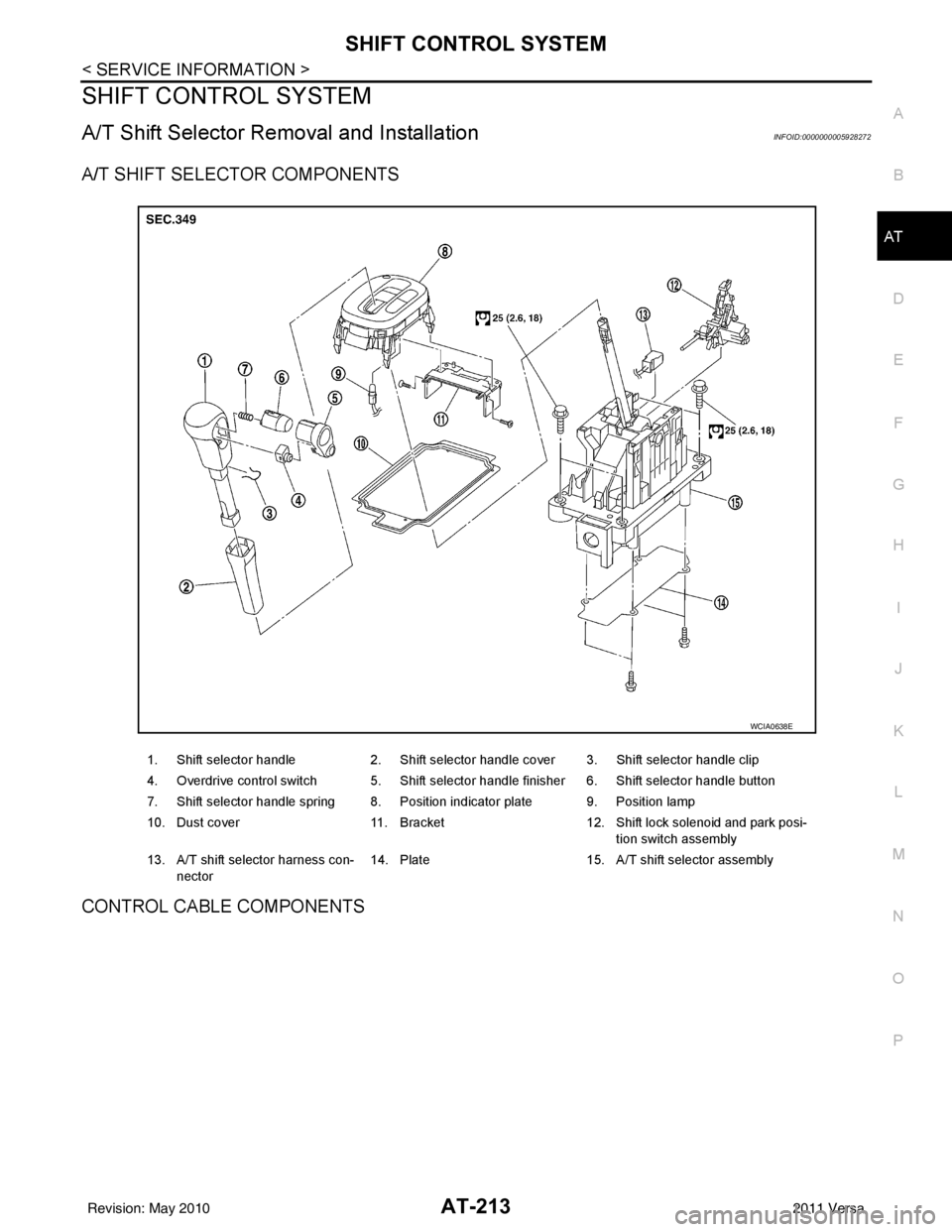
A/T SHIFT SELECTOR COMPONENTS
CONTROL CABLE COMPONENTS
1. Shift selector handle 2. Shift selector handle cover 3. Shift selector handle clip
4. Overdrive control switch 5. Shift selector handle finisher 6. Shift selector handle button
7. Shift selector handle spring 8. Position indicator plate 9. Position lamp
10. Dust cover 11. Bracket12. Shift lock solenoid and park posi-
tion switch assembly
13. A/T shift selector harness con- nector 14. Plate
15. A/T shift selector assembly
WCIA0638E
Revision: May 2010 2011 Versa
Page 233 of 3787
AT-216
< SERVICE INFORMATION >
SHIFT CONTROL SYSTEM
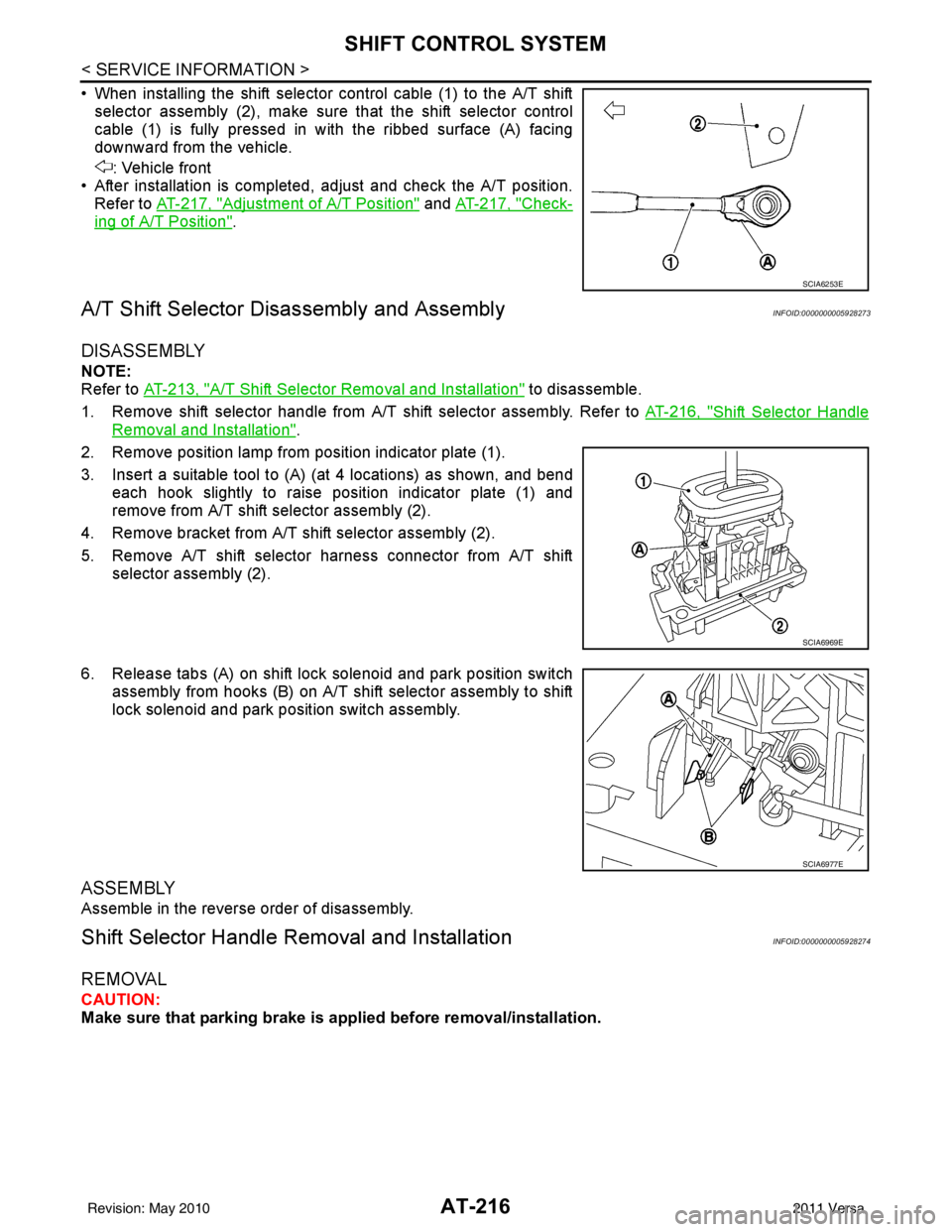
• When installing the shift selector control cable (1) to the A/T shiftselector assembly (2), make sure that the shift selector control
cable (1) is fully pressed in with the ribbed surface (A) facing
downward from the vehicle.
: Vehicle front
• After installation is completed, adjust and check the A/T position. Refer to AT-217, "
Adjustment of A/T Position" and AT-217, "Check-
ing of A/T Position".
A/T Shift Selector Di sassembly and AssemblyINFOID:0000000005928273
DISASSEMBLY
NOTE:
Refer to AT-213, "
A/T Shift Selector Removal and Installation" to disassemble.
1. Remove shift selector handle from A/T shift selector assembly. Refer to AT-216, "
Shift Selector Handle
Removal and Installation".
2. Remove position lamp from position indicator plate (1).
3. Insert a suitable tool to (A) (at 4 locations) as shown, and bend each hook slightly to raise position indicator plate (1) and
remove from A/T shift selector assembly (2).
4. Remove bracket from A/T shift selector assembly (2).
5. Remove A/T shift selector harness connector from A/T shift selector assembly (2).
6. Release tabs (A) on shift lock solenoid and park position switch assembly from hooks (B) on A/T shift selector assembly to shift
lock solenoid and park position switch assembly.
ASSEMBLY
Assemble in the reverse order of disassembly.
Shift Selector Handle Removal and InstallationINFOID:0000000005928274
REMOVAL
CAUTION:
Make sure that parking brake is applied before removal/installation.
SCIA6253E
SCIA6969E
SCIA6977E
Revision: May 2010 2011 Versa
Page 234 of 3787
SHIFT CONTROL SYSTEMAT-217
< SERVICE INFORMATION >
DE
F
G H
I
J
K L
M A
B
AT
N
O P
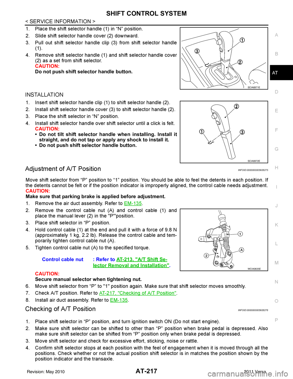
1. Place the shift selector handle (1) in “N” position.
2. Slide shift selector handle cover (2) downward.
3. Pull out shift selector handle clip (3) from shift selector handle (1).
4. Remove shift selector handle (1) and shift selector handle cover (2) as a set from shift selector.
CAUTION:
Do not push shift selector handle button.
INSTALLATION
1. Insert shift selector handle clip (1) to shift selector handle (2).
2. Install shift selector handle cover (3) to shift selector handle (2).
3. Place the shift selector in “N” position.
4. Install shift selector handle over shift selector until a click is felt.
CAUTION:
• Do not tilt shift selector hand le when installing. Install it
straight, and do not tap or ap ply any shock to install it.
• Do not push shift selector handle button.
Adjustment of A/T PositionINFOID:0000000005928275
Move shift selector from “P” position to “1” position. You should be able to feel the detents in each position. If
the detents cannot be felt or if the position indicator is improperly aligned, the control cable needs adjustment.
CAUTION:
Make sure that parking brake is applied before adjustment.
1. Remove the air duct assembly. Refer to EM-135
.
2. Remove the control cable nut (A) and control cable (1) and place the manual lever (2) in the "P'"position.
3. Place shift selector in “P” position.
4. Hold control cable (1) at the end and pull it with a force of 9.8 N (approximately 1 kg, 2.2 lb). Release the control cable and tem-
porarily tighten control cable nut (A).
5. Tighten control cable nut (A) to the specified torque.
CAUTION:
Secure manual selector when tightening nut.
6. Move shift selector from “P” to "1" position again. Make sure that shift selector moves smoothly.
7. Check A/T position. Refer to AT-217, "
Checking of A/T Position".
8. Install air duct assembly. Refer to EM-135
.
Checking of A/T PositionINFOID:0000000005928276
1. Place shift selector in “P” position, and tu rn ignition switch ON (Do not start engine).
2. Make sure shift selector can be shifted to other than “P” position when brake pedal is depressed. Also make sure shift selector can be shifted from “P” position only when brake pedal is depressed.
3. Move shift selector and check for excessive effort, sticking, noise or rattle.
4. Confirm shift selector stops at each position with the feel of engagement when it is moved through all the
positions. Check whether or not the ac tual position shift selector is in matches the position shown by the
position indicator and the transaxle.
SCIA6971E
SCIA6972E
Control cable nut : Refer to AT-213, "A/T Shift Se-
lector Removal and Installation".WCIA0635E
Revision: May 2010 2011 Versa
Page 323 of 3787
AT-306
< SERVICE INFORMATION >
REPAIR FOR COMPONENT PARTS
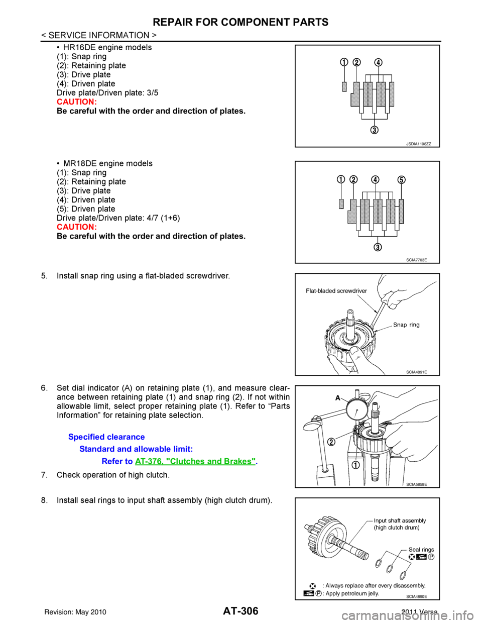
• HR16DE engine models
(1): Snap ring
(2): Retaining plate
(3): Drive plate
(4): Driven plate
Drive plate/Driven plate: 3/5
CAUTION:
Be careful with the order and direction of plates.
• MR18DE engine models
(1): Snap ring
(2): Retaining plate
(3): Drive plate
(4): Driven plate
(5): Driven plate
Drive plate/Driven plate: 4/7 (1+6)
CAUTION:
Be careful with the orde r and direction of plates.
5. Install snap ring using a flat-bladed screwdriver.
6. Set dial indicator (A) on retaining plate (1), and measure clear- ance between retaining plate (1) and snap ring (2). If not within
allowable limit, select proper retaining plate (1). Refer to “Parts
Information” for retaining plate selection.
7. Check operation of high clutch.
8. Install seal rings to input shaft assembly (high clutch drum).
JSDIA1108ZZ
SCIA7703E
SCIA4891E
Specified clearance Standard and allowable limit: Refer to AT-376, "
Clutches and Brakes".
SCIA5858E
SCIA4890E
Revision: May 2010 2011 Versa
Page 367 of 3787
AT-350
< SERVICE INFORMATION >
ASSEMBLY
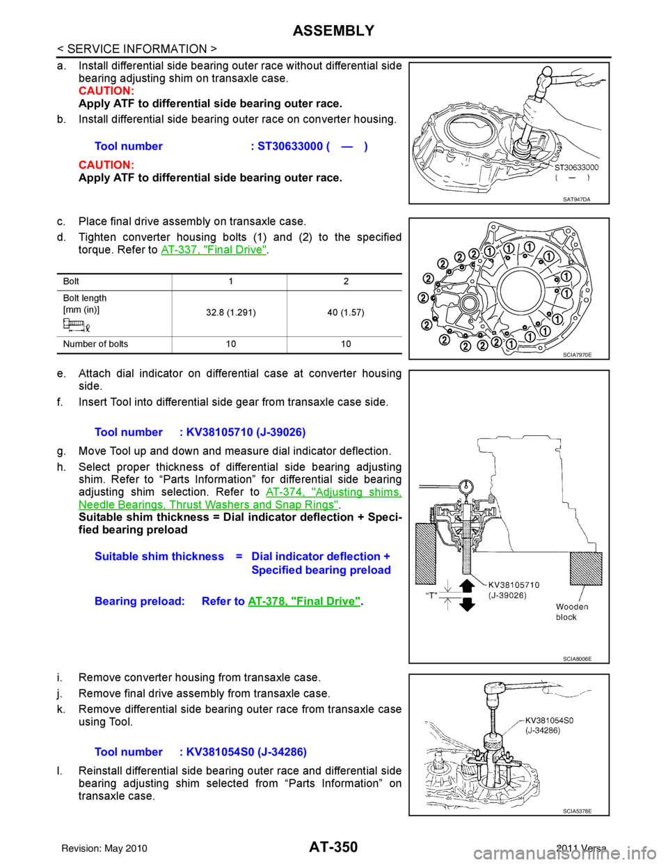
a. Install differential side bearing outer race without differential sidebearing adjusting shim on transaxle case.
CAUTION:
Apply ATF to differential side bearing outer race.
b. Install differential side bearing outer race on converter housing.
CAUTION:
Apply ATF to differential side bearing outer race.
c. Place final drive assembly on transaxle case.
d. Tighten converter housing bolts (1) and (2) to the specified torque. Refer to AT-337, "
Final Drive".
e. Attach dial indicator on differential case at converter housing side.
f. Insert Tool into differential side gear from transaxle case side.
g. Move Tool up and down and measure dial indicator deflection.
h. Select proper thickness of differential side bearing adjusting shim. Refer to “Parts Information” for differential side bearing
adjusting shim selection. Refer to AT-374, "
Adjusting shims,
Needle Bearings, Thrust Washers and Snap Rings".
Suitable shim thickness = Dial indicator deflection + Speci-
fied bearing preload
i. Remove converter housing from transaxle case.
j. Remove final drive assembly from transaxle case.
k. Remove differential side bearing outer race from transaxle case using Tool.
l. Reinstall differential side bearing outer race and differential side bearing adjusting shim selected from “Parts Information” on
transaxle case.Tool number : ST30633000 ( — )
SAT947DA
Bolt
12
Bolt length
[mm (in)] 32.8 (1.291)40 (1.57)
Number of bolts 1010
SCIA7970E
Tool number : KV38105710 (J-39026)
Suitable shim thickness = D ial indicator deflection +
Specified bearing preload
Bearing preload: Refer to AT-378, "
Final Drive".
SCIA8006E
Tool number : KV381054S0 (J-34286)
SCIA5378E
Revision: May 2010 2011 Versa
Page 438 of 3787
![NISSAN TIIDA 2011 Service Service Manual TELEPHONEAV-41
< SERVICE INFORMATION > [AUDIO WITHOUT NAVIGATION]
C
D
E
F
G H
I
J
L
M A
B
AV
N
O P
Bluetooth Control Unit Self-Diagnosis FunctionINFOID:0000000005931302
The Bluetooth control unit has](/img/5/57396/w960_57396-437.png "NISSAN TIIDA 2011 Service Service Manual TELEPHONEAV-41
< SERVICE INFORMATION > [AUDIO WITHOUT NAVIGATION]
C
D
E
F
G H
I
J
L
M A
B
AV
N
O P
Bluetooth Control Unit Self-Diagnosis FunctionINFOID:0000000005931302
The Bluetooth control unit has")
TELEPHONEAV-41
< SERVICE INFORMATION > [AUDIO WITHOUT NAVIGATION]
C
D
E
F
G H
I
J
L
M A
B
AV
N
O P
Bluetooth Control Unit Self-Diagnosis FunctionINFOID:0000000005931302
The Bluetooth control unit has two diagnostic checks. The first diagnostic check is performed automatically
every ignition cycle during control unit initialization. The second diagnostic check is performed by the techni-
cian using the steering wheel audio control switches prior to trouble diagnosis.
BLUETOOTH CONTROL UNIT INITIALIZATION CHECKS
• Internal control unit failure
• Bluetooth antenna connection open or shorted
• Steering wheel audio control swit ches (SEND/END) stuck closed
• Vehicle speed pulse count
• Bluetooth Microphone connection test (with playback to operator)
• Bluetooth inquiry check
SELF-DIAGNOSIS MODE
1. Turn ignition switch to ACC or ON.
2. Wait for the Bluetooth system to complete initialization and the Bluetooth ON indicator to stop flashing. This may take up to 10 seconds.
3. Press and hold the steering wheel audio control switch SEND
button for at least 5 seconds. The Bluetooth system will begin to
play a verbal prompt.
4. While the prompt is playing, momentarily press both the steering wheel audio control switches SEND and END buttons simulta-
neously. The Bluetooth system will sound a 5 second beep.
5. While the beep is sounding, momentarily press both the steering
wheel audio control switches SEND and END buttons simulta-
neously again.
6. The Bluetooth system has now entered into the diagnostic
mode. Results of the diagnostic checks will be verbalized to the
technician. Refer to AV-41, "
Workflow".
7. If there are no failure records to report, the speed pulse count
will be reported next.
8. After the speed pulse count is reported, an interactive Bluetooth microphone test will be performed. Follow the voice pr ompt. If the Bluetooth microphone test fails refer to
AV-41, "
Workflow".
9. Self-diagnosis mode is complete when the voice prompt says "All diagnostic functions completed". A short beep is heard.
WorkflowINFOID:0000000005931303
WKIA6003E
WKIA6004E
Flashing Pattern
(Bluetooth ON indicator) Failure Message
Action
1 "Internal failure" Replace Bluetooth control unit. Refer to AV-
46, "Removal and Installation".
2 "Bluetooth antenna open" 1. Inspect harness connection.
2. Replace Bluetooth antenna. Refer to AV- 4 6 , "
Removal and Installation".
3
"Bluetooth antenna shorted"
Revision: May 2010 2011 Versa
Page 439 of 3787
![NISSAN TIIDA 2011 Service Service Manual AV-42
< SERVICE INFORMATION >[AUDIO WITHOUT NAVIGATION]
TELEPHONE
Power Supply and Ground Circuit Inspection for Bluetooth Control Unit
INFOID:0000000005931304
1.CHECK FUSES
Make sure the following fu](/img/5/57396/w960_57396-438.png "NISSAN TIIDA 2011 Service Service Manual AV-42
< SERVICE INFORMATION >[AUDIO WITHOUT NAVIGATION]
TELEPHONE
Power Supply and Ground Circuit Inspection for Bluetooth Control Unit
INFOID:0000000005931304
1.CHECK FUSES
Make sure the following fu")
AV-42
< SERVICE INFORMATION >[AUDIO WITHOUT NAVIGATION]
TELEPHONE
Power Supply and Ground Circuit Inspection for Bluetooth Control Unit
INFOID:0000000005931304
1.CHECK FUSES
Make sure the following fuses for the Bluetooth control unit are not blown.
OK or NG
OK >> GO TO 2.
NG >> If fuse is blown, be sure to eliminate cause of malfunction before installing new fuse. Refer to PG-
4, "Schematic".
2.CHECK POWER SUPPLY CIRCUIT
1. Disconnect Bluetooth control unit connector B121.
2. Check voltage between connector terminals and ground as fol- lows.
OK or NG
OK >> GO TO 3.
NG >> Check harness for open between Bluetooth control unit and fuse.
3.CHECK GROUND CIRCUITS
1. Turn ignition switch OFF.
4 "Phone/Send for the Hands Free Phone
System is stuck"
Check steering wheel audio control switch-
es. Refer to
AV- 2 2 , "
Steering Switch Check
(With Bluetooth)".
5 "Phone/End for the Hands Free Phone
System is stuck"
– "Bluetooth Microphone test" (failed interac-
tive test) 1. Inspect harness between Bluetooth
control unit and Bluetooth micro-
phone.
2. Replace Bluetooth microphone. Refer to AV- 4 6 , "
Removal and Installation".
Flashing Pattern
(Bluetooth ON indicator) Failure Message Action
Te r m i n a l s
Ignition Switch Fuse No.
Connector Terminal
B121 1
All positions27
2 ACC/ON20
3 ON/START3
Terminals Ignition switch position
(+) (–) OFF ACC ON
Connector Terminal
B121 1
Ground Battery
voltage Battery
voltage Battery
voltage
20 VBattery
voltage Battery
voltage
30 V0V Battery
voltage
WKIA4389E
Revision: May 2010 2011 Versa
Page 498 of 3787

BCS-8
< SERVICE INFORMATION >
BCM (BODY CONTROL MODULE)
CAN Communication System Description
INFOID:0000000005929256
Refer to LAN-7, "System Description".
Panic alarm •Key switch
•KeyfobIPDM E/R
Vehicle security system • All door switches
•Keyfob
• Door lock/unlock switch
• Trunk key cylinder switch (Se-
dan)
• Front door key cylinder switch LH • IPDM/ER
• Security indicator lamp
Battery save r control • Ignition switch
• Combination switch
IPDM E/R
Headlamp Combination switch IPDM E/R
Tail lamp Combination switchIPDM E/R
Front fog lamp (with front fog lamps) Combination switch IPDM E/R
Turn signal lamp Combination switch• Turn signal lamp
• Combination meter
Hazard lamp Hazard switch• Turn signal lamp
• Combination meter
Room lamp timer •Key switch
•Keyfob
• Main power window and door
lock/unlock switch
• Front door switch LH
• All door switch Interior room lamp
Back door switch signal (Hatchback) Back door lock assembly Luggage room lamp
Back door lock signal (Hatchback) Back door lock assembly Back door opener
Trunk lamp switch signal (Sedan) Trunk lamp switch and trunk re-
lease solenoidLuggage room lamp
Trunk lid opener signal (Sedan) Trunk lamp switch and trunk re-
lease solenoid
Trunk lid opener
Key warning chime •Key switch
• Front door switch LHCombination meter (warning buzzer)
Light warning chime • Combination switch
•Key switch
• Front door switch LHCombination meter (warning buzzer)
Seat belt warning chime • Seat belt buckle switch LH
• Ignition switch
Combination meter (warning buzzer)
Front wiper and washer system • Combination switch
• Ignition switchIPDM E/R
Rear window defogger Rear window defogger switch IPDM E/R
Rear wiper and washer system
(Hatchback) • Combination switch
• Ignition switch
Rear wiper motor
A/C switch signal Front air controlECM
Blower fan switch signal Front air controlECM
A/C indicator signal Front air controlA/C indicator
Low tire pressure warning system Remote keyless entry receiver Combination meter System
Input Output
Revision: May 2010 2011 Versa
Page 503 of 3787
BCM (BODY CONTROL MODULE)BCS-13
< SERVICE INFORMATION >
C
DE
F
G H
I
J
L
M A
B
BCS
N
O P
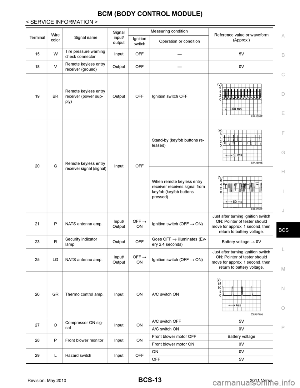
15 W Tire pressure warning
check connector
Input OFF
—5V
18 V Remote keyless entry
receiver (ground) Output OFF
—0V
19 BR Remote keyless entry
receiver (power sup-
ply) Output OFF Ignition switch OFF
20 G Remote keyless entry
receiver signal (signal)
Input OFFStand-by (keyfob buttons re-
leased)
When remote keyless entry
receiver receives signal from
keyfob (keyfob buttons
pressed)
21 P NATS antenna amp. Input/
Output OFF
→
ON Ignition switch (OFF → ON) Just after turning ignition switch
ON: Pointer of tester should
move for approx. 1 second, then
return to battery voltage.
23 R Security indicator
lamp Output OFF
Goes OFF
→ illuminates (Ev-
ery 2.4 seconds) Battery voltage
→ 0V
25 LG NATS antenna amp. Input/
Output OFF
→
ON Ignition switch (OFF → ON) Just after turning ignition switch
ON: Pointer of tester should
move for approx. 1 second, then return to battery voltage.
26 GR Thermo control amp. Input ON A/C switch ON
27 O Compressor ON sig-
nal Input ONA/C switch OFF
5V
A/C switch ON 0V
28 P Front blower monitor Input ON Front blower motor OFF
Battery voltage
Front blower motor ON 0V
29 L Hazard switch Input OFFON
0V
OFF 5V
Te r m i n a l
Wire
color Signal name Signal
input/
output Measuring condition
Reference value or waveform
(Approx.)
Ignition
switch Operation or condition
LIIA1893E
LIIA1894E
LIIA1895E
ZJIA0719J
Revision: May 2010
2011 Versa
Page 505 of 3787

BCM (BODY CONTROL MODULE)BCS-15
< SERVICE INFORMATION >
C
DE
F
G H
I
J
L
M A
B
BCS
N
O P
426Y Trunk lamp switch Input OFF ON (trunk open)
0V
OFF (trunk closed) Battery voltage
43
5R Back door switch Input OFF ON (open) 0V
OFF (closed)
Battery voltage
44
5LG Rear wiper auto stop Input ON Rear wiper operating 0
Rear wiper stopped
Battery
45
7GR Lock switch Input OFFON (lock)
0V
OFF Battery voltage
46
7L Unlock switch Input OFFON (unlock)
0V
OFF Battery voltage
47 BR Front door switch LH Input OFF ON (open)
0V
OFF (closed) Battery voltage
48 O Rear door switch LH Input OFF ON (open)
0V
OFF (closed) Battery voltage
49 P Luggage room lamp Output OFF Any door open (ON)
0V
All doors closed (OFF) Battery voltage
50 SB A/C indicator Output ONA/C OFF
0
A/C ON Battery voltage
53
5R Back door lock assem-
bly (actuator)
Output OFF Back door (open)
Battery voltage
53
6R Trunk lamp switch and
trunk release solenoid Output OFF Trunk lid (open)
Battery voltage
55
5V Rear wiper motor out-
put
Output ONOFF
0
ON Battery voltage
56 R Battery saver output Output OFF
15 minutes after ignition
switch is turned OFF 0V
ON — Battery voltage
57 LG Battery power supply Input OFF —Battery voltage
59
7G Front door lock actua-
tor LH (unlock)
Output OFFOFF (neutral)
0V
ON (unlock) Battery voltage
60 V Turn signal (left) Output ON Turn left ON
61 W Turn signal (right) Output ON Turn right ON
Te r m i n a l
Wire
color Signal name Signal
input/
output Measuring condition
Reference value or waveform
(Approx.)
Ignition
switch Operation or condition
SKIA3009J
SKIA3009J
Revision: May 2010
2011 Versa