battery NISSAN TIIDA 2011 Service Repair Manual
[x] Cancel search | Manufacturer: NISSAN, Model Year: 2011, Model line: TIIDA, Model: NISSAN TIIDA 2011Pages: 3787, PDF Size: 78.35 MB
Page 3749 of 3787
PRECAUTIONWW-3
< SERVICE INFORMATION >
C
DE
F
G H
I
J
L
M A
B
WW
N
O P
5. When the repair work is completed, return the ignition switch to the ″LOCK ″ position before connecting
the battery cables. (At this time, the steering lock mechanism will engage.)
6. Perform a self-diagnosis check of al l control units using CONSULT-III.
Precaution for Procedure without Cowl Top CoverINFOID:0000000005929205
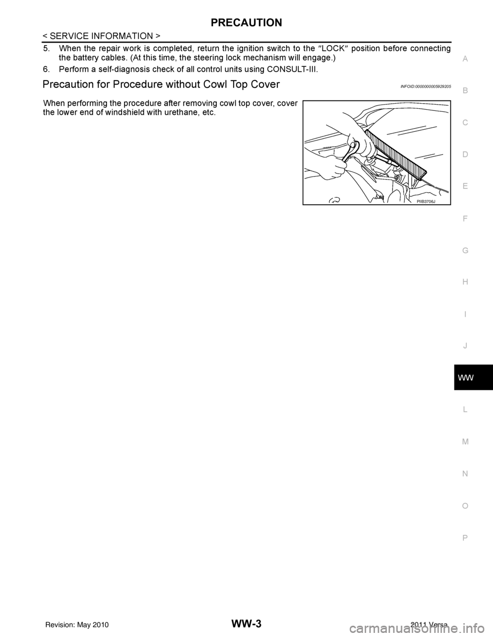
When performing the procedure after removing cowl top cover, cover
the lower end of windshield with urethane, etc.
PIIB3706J
Revision: May 2010 2011 Versa
Page 3751 of 3787
FRONT WIPER AND WASHER SYSTEMWW-5
< SERVICE INFORMATION >
C
DE
F
G H
I
J
L
M A
B
WW
N
O P
FRONT WIPER AND WASHER SYSTEM
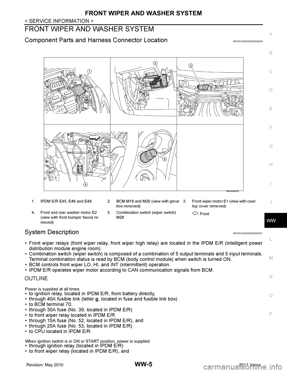
Component Parts and Har ness Connector LocationINFOID:0000000005929206
System DescriptionINFOID:0000000005929207
• Front wiper relays (front wiper relay, front wiper high relay) are located in the IPDM E/R (intelligent power
distribution module engine room).
• Combination switch (wiper switch) is composed of a combination of 5 output terminals and 5 input terminals.
Terminal combination status is read by BCM (body control module) when switch is turned ON.
• BCM controls front wiper LO, HI, and INT (intermittent) operation.
• IPDM E/R operates wiper motor accordi ng to CAN communication signals from BCM.
OUTLINE
Power is supplied at all times• to ignition relay, located in IPDM E/R, from battery directly,
• through 40A fusible link (letter g, located in fuse and fusible link box)
• to BCM terminal 70,
• through 30A fuse (No. 39, located in IPDM E/R)
• to front wiper relay located in IPDM E/R
• through 15A fuse (No. 52, located in IPDM E/R), and
• through 20A fuse (No. 53, located in IPDM E/R)
• to CPU located in IPDM E/R.
When ignition switch is in ON or START position, power is supplied • through ignition relay (located in IPDM E/R)
• to front wiper relay (located in IPDM E/R), and
1. IPDM E/R E45, E46 and E48 2. BCM M18 and M20 (view with glove
box removed)3. Front wiper motor E1
(view with cowl
top cover removed)
4. Front and rear washer motor E2 (view with front bumper fascia re-
moved) 5. Combination switch (wiper switch)
M28 : Front
WKIA5467E
Revision: May 2010
2011 Versa
Page 3761 of 3787
FRONT WIPER AND WASHER SYSTEMWW-15
< SERVICE INFORMATION >
C
DE
F
G H
I
J
L
M A
B
WW
N
O P
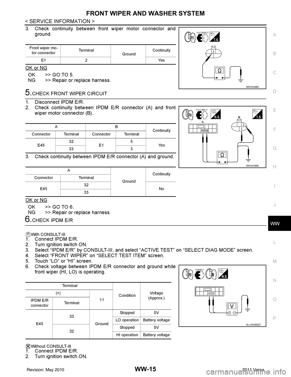
3. Check continuity between front wiper motor connector and ground.
OK or NG
OK >> GO TO 5.
NG >> Repair or replace harness.
5.CHECK FRONT WIPER CIRCUIT
1. Disconnect IPDM E/R.
2. Check continuity between IPDM E/R connector (A) and front wiper motor connector (B).
3. Check continuity between IPDM E/R connector (A) and ground.
OK or NG
OK >> GO TO 6.
NG >> Repair or replace harness.
6.CHECK IPDM E/R
With CONSULT-lIl
1. Connect IPDM E/R.
2. Turn ignition switch ON.
3. Select “IPDM E/R” by CONSULT-III, and sele ct “ACTIVE TEST” on “SELECT DIAG MODE” screen.
4. Select “FRONT WIPER” on “SELECT TEST ITEM” screen.
5. Touch “LO” or “HI” screen.
6. Check voltage between IPDM E/R connector and ground while front wiper (HI, LO) is operating.
Without CONSULT-llI
1. Connect IPDM E/R.
2. Turn ignition switch ON.
Front wiper mo-
tor connector Te r m i n a l
GroundContinuity
E1 2 Yes
WKIA5488E
AB
Continuity
Connector Terminal Connector Terminal
E45 32
E1 5
Ye s
33 3
A GroundContinuity
Connector Terminal
E45 32
No
33
WKIA5489E
Te r m i n a l
ConditionVo l ta g e
(Approx.)
(+)
(-)
IPDM E/R
connector Te r m i n a l
E45 33
GroundStopped 0V
LO operation Battery voltage
32 Stopped 0V
HI operation Battery voltage
ALLIA0368ZZ
Revision: May 2010 2011 Versa
Page 3762 of 3787
WW-16
< SERVICE INFORMATION >
FRONT WIPER AND WASHER SYSTEM
3. Start auto active test. Refer to PG-20, "Auto Active Test" .
4. Check voltage between IPDM E/R connector and ground while front wiper (HI, LO) is operating.
OK or NG
OK >> Replace front wiper motor. Refer to WW-22, "Removal and Installation of Front Wiper Drive
Assembly" .
NG >> Replace IPDM E/R. Refer to PG-28, "
Removal and Installation of IPDM E/R" .
Front Wiper Does Not Return to Stop Positi on (After Front Wiper Operates for 10 Sec-
onds, They Stop for 20 Second s, and After Repeating the Operation Five Times, They
Become Inoperative)
INFOID:0000000005929218
CAUTION:
• When auto-stop signal has not varied for 10 seconds or longer while IPDM E/R is operating front wip-
ers, IPDM E/R considers that front wipers are locked, and stops wiper output. That causes this symp-
tom.
• This status can be checked by “DATA MONITOR” of “IPDM E/R” on which “WIPER PROT” item
shows “BLOCK”.
1.CHECK FRONT WIPER STOP SIGNAL
With CONSULT-lIl
Select “IPDM E/R” on CONSULT-III. With “DATA MONITOR”, make sure that “WIP AUTO STOP” turns “ACT
P” - “STOP P” linked with wiper operation.
Without CONSULT-llI
GO TO 2.
OK or NG
OK >> Replace IPDM E/R. Refer to PG-28, "Removal and Installation of IPDM E/R" .
NG >> GO TO 2.
2.CHECK IPDM E/R
1. Turn ignition switch ON.
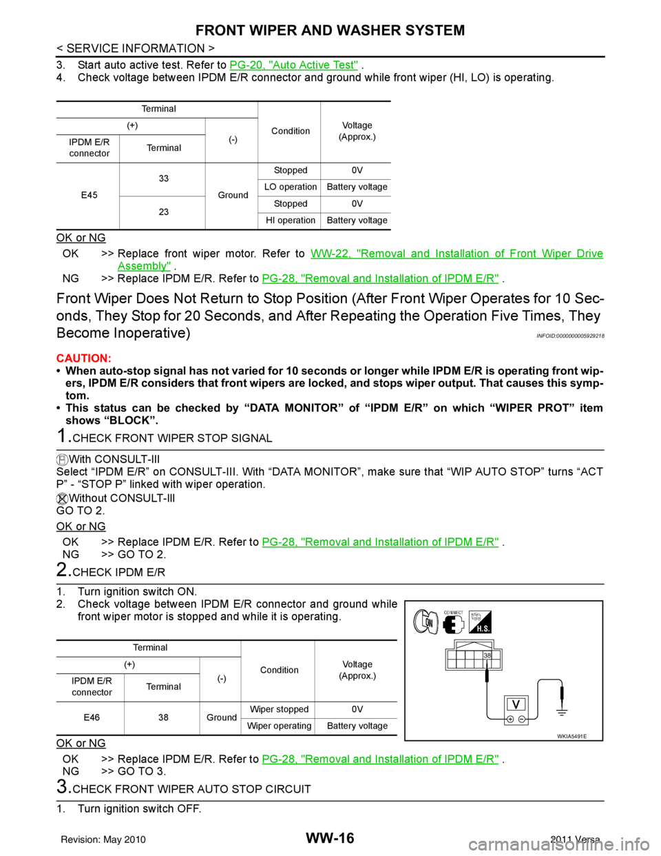
2. Check voltage between IPDM E/R connector and ground while front wiper motor is stopped and while it is operating.
OK or NG
OK >> Replace IPDM E/R. Refer to PG-28, "Removal and Installation of IPDM E/R" .
NG >> GO TO 3.
3.CHECK FRONT WIPER AUTO STOP CIRCUIT
1. Turn ignition switch OFF.
Te r m i n a l
ConditionVo l ta g e
(Approx.)
(+)
(-)
IPDM E/R
connector Te r m i n a l
E45 33
GroundStopped 0V
LO operation Battery voltage
23 Stopped 0V
HI operation Battery voltage
Te r m i n a l
ConditionVo l ta g e
(Approx.)
(+)
(-)
IPDM E/R
connector Te r m i n a l
E46 38 Ground Wiper stopped 0V
Wiper operating Battery voltage
WKIA5491E
Revision: May 2010 2011 Versa
Page 3764 of 3787

WW-18
< SERVICE INFORMATION >
FRONT WIPER AND WASHER SYSTEM
1. Connect IPDM E/R.
2. Turn ignition ON.
3. Select “IPDM E/R” on CONSULT-III, and select “ACTIVE TEST” on “SELECT DIAG MODE” screen.
4. Select “FRONT WIPER” on “SELECT TEST ITEM” screen.
5. Touch “LO” screen.
6. Check voltage between IPDM E/R connector and ground while front wiper LO is operating.
Without CONSULT-lIl
1. Connect IPDM E/R.
2. Turn ignition ON.
3. Start auto active test. Refer to PG-20, "
Auto Active Test" .
4. Check voltage between IPDM E/R connector and ground while front wiper LO is operating.
OK or NG
OK >> Replace front wiper motor. Refer to WW-22, "Removal and Installation of Front Wiper Drive
Assembly" .
NG >> Replace IPDM E/R. Refer to PG-28, "
Removal and Installation of IPDM E/R" .
Only Front Wiper High Does Not OperateINFOID:0000000005929220
1.ACTIVE TEST
With CONSULT-Ill
1. Select “IPDM E/R” on CONSULT-III, and sele ct “ACTIVE TEST” on “SELECT DIAG MODE” screen.
2. Select “FRONT WIPER” on “SELECT TEST ITEM” screen.
3. Touch “HI” screen.
Without CONSULT-lIl
Start auto active test. Refer to PG-20, "
Auto Active Test" .
Does front wiper operate normally?
YES >> Refer to LT-65, "Combination Switch Inspection" .
NO >> GO TO 2.
2.CHECK FRONT WIPER MOTOR CIRCUIT
1. Turn ignition switch OFF.
2. Disconnect IPDM E/R connector E45 and front wiper motor connector E1.
Te r m i n a l
Continuity
(+)
(-)
IPDM E/R
connector Te r m i n a l
E45 33Ground Battery voltage
Te r m i n a l Continuity
(+)
(-)
IPDM E/R
connector Te r m i n a l
E45 33Ground Battery voltage
WKIA5496E
Revision: May 2010 2011 Versa
Page 3765 of 3787
FRONT WIPER AND WASHER SYSTEMWW-19
< SERVICE INFORMATION >
C
DE
F
G H
I
J
L
M A
B
WW
N
O P
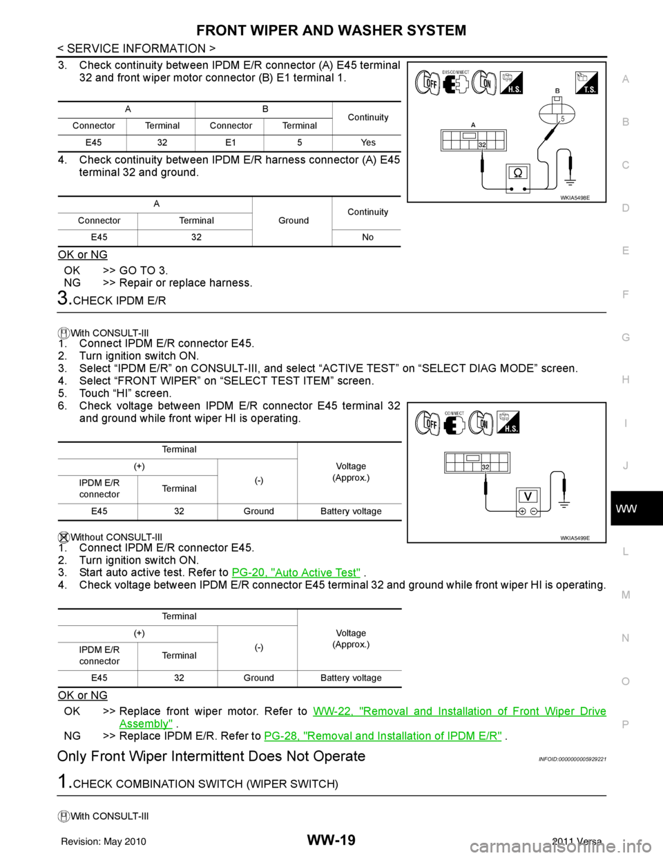
3. Check continuity between IPDM E/R connector (A) E45 terminal 32 and front wiper motor connector (B) E1 terminal 1.
4. Check continuity between IPDM E/R harness connector (A) E45 terminal 32 and ground.
OK or NG
OK >> GO TO 3.
NG >> Repair or replace harness.
3.CHECK IPDM E/R
With CONSULT-lIl1. Connect IPDM E/R connector E45.
2. Turn ignition switch ON.
3. Select “IPDM E/R” on CONSUL T-III, and select “ACTIVE TEST” on “SELECT DIAG MODE” screen.
4. Select “FRONT WIPER” on “SELECT TEST ITEM” screen.
5. Touch “HI” screen.
6. Check voltage between IPDM E/R connector E45 terminal 32 and ground while front wiper HI is operating.
Without CONSULT-lIl
1. Connect IPDM E/R connector E45.
2. Turn ignition switch ON.
3. Start auto active test. Refer to PG-20, "
Auto Active Test" .
4. Check voltage between IPDM E/R connector E45 terminal 32 and ground while front wiper HI is operating.
OK or NG
OK >> Replace front wiper motor. Refer to WW-22, "Removal and Installation of Front Wiper Drive
Assembly" .
NG >> Replace IPDM E/R. Refer to PG-28, "
Removal and Installation of IPDM E/R" .
Only Front Wiper Intermittent Does Not OperateINFOID:0000000005929221
1.CHECK COMBINATION SW ITCH (WIPER SWITCH)
With CONSULT-lIl
AB
Continuity
Connector Terminal Connector Terminal
E45 32E1 5Yes
A GroundContinuity
Connector Terminal
E45 32 No
WKIA5498E
Te r m i n a l
Vo l ta g e
(Approx.)
(+)
(-)
IPDM E/R
connector Te r m i n a l
E45 32Ground Battery voltage
Te r m i n a l Vo l ta g e
(Approx.)
(+)
(-)
IPDM E/R
connector Te r m i n a l
E45 32Ground Battery voltage
WKIA5499E
Revision: May 2010 2011 Versa
Page 3778 of 3787
WW-32
< SERVICE INFORMATION >
REAR WIPER AND WASHER SYSTEM
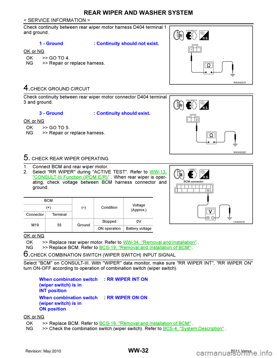
Check continuity between rear wiper motor harness D404 terminal 1
and ground.
OK or NG
OK >> GO TO 4.
NG >> Repair or replace harness.
4.CHECK GROUND CIRCUIT
Check continuity between rear wiper motor connector D404 terminal
3 and ground.
OK or NG
OK >> GO TO 5.
NG >> Repair or replace harness.
5. CHECK REAR WIPER OPERATING
1. Connect BCM and rear wiper motor.
2. Select "RR WIPER" during "ACTIVE TEST". Refer to WW-13,
"CONSULT-III Function (IPDM E/R)" . When rear wiper is oper-
ating, check voltage between BCM harness connector and
ground.
OK or NG
OK >> Replace rear wiper motor. Refer to WW-34, "Removal and Installation" .
NG >> Replace BCM. Refer to BCS-19, "
Removal and Installation of BCM" .
6.CHECK COMBINATION SWITCH (W IPER SWITCH) INPUT SIGNAL
Select "BCM" on CONSULT-III. With "WIPER" data monitor, make sure "RR WIPER INT", "RR WIPER ON"
turn ON-OFF according to operation of combination switch (wiper switch).
OK or NG
OK >> Replace BCM. Refer to BCS-19, "Removal and Installation of BCM" .
NG >> Check the combination switch (wiper switch). Refer to BCS-4, "
System Description" .
1 - Ground
: Continuity should not exist.
WKIA5531E
3 - Ground : Continuity should exist.
WKIA5532E
BCM
(–) Condition Vol tag e
(Approx.)
(+)
Connector Terminal
M19 55 Ground Stopped
0V
ON operation Battery voltage
LKIA0551E
When combination switch
(wiper switch) is in
INT position : RR WIPER INT ON
When combination switch
(wiper switch) is in
ON position : RR WIPER ON ON
Revision: May 2010
2011 Versa
Page 3780 of 3787
WW-34
< SERVICE INFORMATION >
REAR WIPER AND WASHER SYSTEM
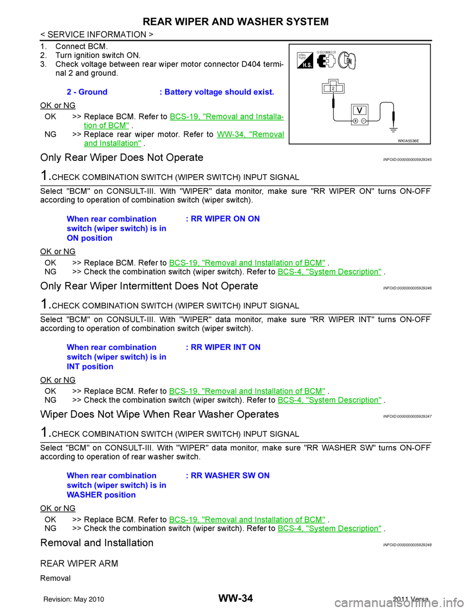
1. Connect BCM.
2. Turn ignition switch ON.
3. Check voltage between rear wiper motor connector D404 termi-nal 2 and ground.
OK or NG
OK >> Replace BCM. Refer to BCS-19, "Removal and Installa-
tion of BCM" .
NG >> Replace rear wiper motor. Refer to WW-34, "
Removal
and Installation" .
Only Rear Wiper Does Not OperateINFOID:0000000005929245
1.CHECK COMBINATION SWITCH (WIPER SWITCH) INPUT SIGNAL
Select "BCM" on CONSULT-III. With "WIPER" data monitor, make sure "RR WIPER ON" turns ON-OFF
according to operation of combination switch (wiper switch).
OK or NG
OK >> Replace BCM. Refer to BCS-19, "Removal and Installation of BCM" .
NG >> Check the combination switch (wiper switch). Refer to BCS-4, "
System Description" .
Only Rear Wiper Intermittent Does Not OperateINFOID:0000000005929246
1.CHECK COMBINATION SWITCH (W IPER SWITCH) INPUT SIGNAL
Select "BCM" on CONSULT-III. With "WIPER" data monitor, make sure "RR WIPER INT" turns ON-OFF
according to operation of combination switch (wiper switch).
OK or NG
OK >> Replace BCM. Refer to BCS-19, "Removal and Installation of BCM" .
NG >> Check the combination switch (wiper switch). Refer to BCS-4, "
System Description" .
Wiper Does Not Wipe When Rear Washer OperatesINFOID:0000000005929247
1.CHECK COMBINATION SWITCH (WIPER SWITCH) INPUT SIGNAL
Select "BCM" on CONSULT-III. With "WIPER" data monitor, make sure "RR WASHER SW" turns ON-OFF
according to operation of rear washer switch.
OK or NG
OK >> Replace BCM. Refer to BCS-19, "Removal and Installation of BCM" .
NG >> Check the combination switch (wiper switch). Refer to BCS-4, "
System Description" .
Removal and InstallationINFOID:0000000005929248
REAR WIPER ARM
Removal
2 - Ground: Battery voltage should exist.
WKIA5536E
When rear combination
switch (wiper switch) is in
ON position : RR WIPER ON ON
When rear combination
switch (wiper switch) is in
INT position : RR WIPER INT ON
When rear combination
switch (wiper switch) is in
WASHER position : RR WASHER SW ON
Revision: May 2010
2011 Versa