change key battery NISSAN TIIDA 2011 Service Repair Manual
[x] Cancel search | Manufacturer: NISSAN, Model Year: 2011, Model line: TIIDA, Model: NISSAN TIIDA 2011Pages: 3787, PDF Size: 78.35 MB
Page 497 of 3787
BCM (BODY CONTROL MODULE)BCS-7
< SERVICE INFORMATION >
C
DE
F
G H
I
J
L
M A
B
BCS
N
O P
• When CAN communication operation is detected, it switches to CAN communication status.
• When a state of the following switches changes , it switches to CAN communication state:
- Ignition switch
- Key switch (without Intelligent Key)
- Key switch and ignition knob switch (with Intelligent Key)
- Hazard switch
- Door lock/unlock switch (with power door locks)
- Front door switch (LH, RH)
- Rear door switch (LH, RH)
- Back door lock assembly (Hatchback)
- Trunk key cylinder switch (Sedan)
- Trunk lamp switch and trunk release solenoid (Sedan)
- Combination switch (passing, lighting switch 1st position, front fog lamp)
- Keyfob (lock/unlock signal) (with power door locks)
- Front door key cylinder switch LH
• When control performed only by BCM is required by switch, it shifts to CAN communication inactive mode.
• Status of combination switch reading function is changed.
SYSTEMS CONTROLLED BY BCM DIRECTLY
• Power door lock system (with power door locks). Refer to BL-23, "System Description" .
• Remote keyless entry system. Refer to BL-58, "
System Description" .
• Power window system (with power windows). Refer to GW-19, "
System Description" . NOTE
• Sunroof system (with sunroof). Refer to RF-11, "System Description". NOTE
• Room lamp timer. Refer to LT-93, "System Description" .
• Rear wiper and washer system (Hatchback). Refer to WW-27, "
System Description" .
NOTE:
Power supply only. No system control.
SYSTEMS CONTROLLED BY BCM AND IPDM E/R
• Panic system. Refer to BL-58, "System Description" .
• Vehicle security (theft warning) system. Refer to BL-218, "
System Description" .
• NVIS(NATS) system. Refer to BL-246, "
System Description" .
• Headlamp, tail lamp and battery saver control systems. Refer to LT-74, "
System Description", LT- 5 , "System
Description" or LT-27, "System Description" .
• Front fog lamp (with front fog lamps). Refer to LT-41, "
System Description" .
• Front wiper and washer system. Refer to WW-5, "
System Description" .
• Rear window defogger system. Refer to GW-51, "
System Description" .
SYSTEMS CONTROLLED BY BCM AND COMBINATION METER
• Warning chime. Refer to DI-43, "System Description" .
• Turn signal and hazard warning lamps. Refer to LT-50, "
System Description" .
SYSTEMS CONTROLLED BY BCM AND INTELLIGENT KEY UNIT (WITH INTELLIGENT KEY)
• Intelligent Key system. Refer to BL-88, "System Description" .
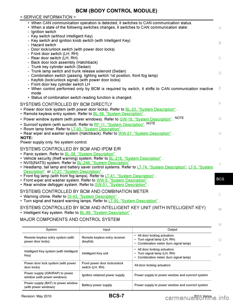
MAJOR COMPONENTS AND CONTROL SYSTEM
System Input Output
Remote keyless entry system (with
power door locks) Remote keyless entry receiver
(keyfob)• All door locking actuators
• Turn signal lamp (LH, RH)
• Combination meter (turn signal lamp)
Intelligent Key system (with Intelligent
Key) Intelligent Key unit• All door locking actuators
• Turn signal lamp (LH, RH)
• Combination meter (turn signal lamp)
Power door lock system (with power
door locks) Front power door lock/unlock
switch (LH, RH)
All door locking actuators
Power supply (IGN /RAP) to power
window (with power windows) Ignition retained power supply Power supply to power window and sunroof system
Power supply (BAT) to power window
(with power windows) Battery power supply
Power supply to power window and sunroof system
Revision: May 2010 2011 Versa
Page 509 of 3787
BCM (BODY CONTROL MODULE)BCS-19
< SERVICE INFORMATION >
C
DE
F
G H
I
J
L
M A
B
BCS
N
O P
Contents displayed
No malfunction>>Inspection End
Malfunction in CAN communication system>>After printing the monitor items, go to “CAN System”. Refer to
LAN-17, "
Trouble Diagnosis Flow Chart".
ConfigurationINFOID:0000000005929263
DESCRIPTION
CONFIGURATION has three functions as follows:
• READ CONFIGURATION is the function to read (e xtract) vehicle configuration of current BCM.
• WRITE CONFIGURATION-Manual selection is the functi on to select and write vehicle configuration on BCM
manually.
• WRITE CONFIGURATION-Config file is the function to write vehicle configuration with the data extracted
from current BCM.
• For READ CONFIGURATION and WRITE CONFIGURATION -Config file, refer to CONSULT-III Operation
Manual.
• For WRITE CONFIGURATION-Manual selection using the following flow chart, identify the correct model
and configuration list. Confirm and/or change setting val ue for each item according to the configuration list.
Depending on CONSULT-III software version being used, some or all of the write configuration items shown
in the following configuration lists may be display ed. If an item does not appear on the CONSULT-III WRITE
CONFIGURATION-Manual selection screen(s), then it is an auto setting item and it cannot be manually set
or changed.
NOTE:
Confirm vehicle model on IDENTIFICATION PLATE. Refer to GI-43, "
Model Variation".
CAUTION:
• When replacing BCM, you must perform WRITE CONFIGURATION with CONSULT-III.
• Complete the procedure of WRITE CONFIGURATION in order.
• If you set incorrect WRITE CONF IGURATION, incidents will occur.
• Configuration is different for each vehicle model. Confirm conf iguration of each vehicle model.
Removal and Installation of BCMINFOID:0000000005929264
REMOVAL
CAUTION:
Before replacing BCM, perform “READ CONFIGURATI ON" to save or print current vehicle specifica-
tion. Refer to BCS-19, "
Configuration".
1. Disconnect the battery negative terminal.
2. Remove the glove box. Refer to IP-12, "
Removal and Installation".
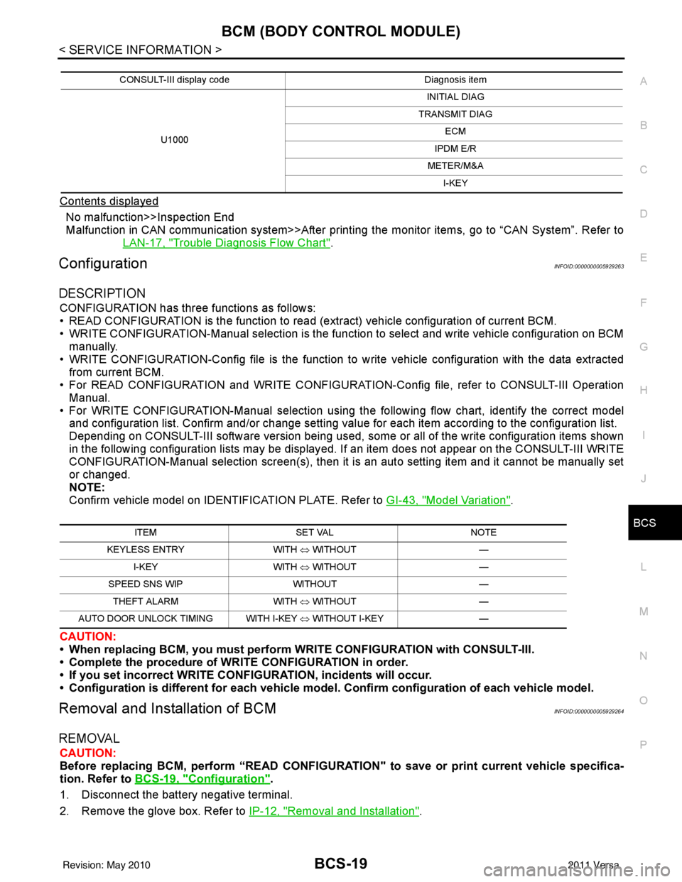
CONSULT-III display code Diagnosis item
U1000 INITIAL DIAG
TRANSMIT DIAG ECM
IPDM E/R
METER/M&A I-KEY
ITEM SET VAL NOTE
KEYLESS ENTRY WITH ⇔ WITHOUT —
I-KEY WITH ⇔ WITHOUT —
SPEED SNS WIP WITHOUT —
THEFT ALARM WITH ⇔ WITHOUT —
AUTO DOOR UNLOCK TIMING WITH I-KEY ⇔ WITHOUT I-KEY —
Revision: May 2010 2011 Versa
Page 579 of 3787
REMOTE KEYLESS ENTRY SYSTEMBL-69
< SERVICE INFORMATION >
C
DE
F
G H
J
K L
M A
B
BL
N
O P
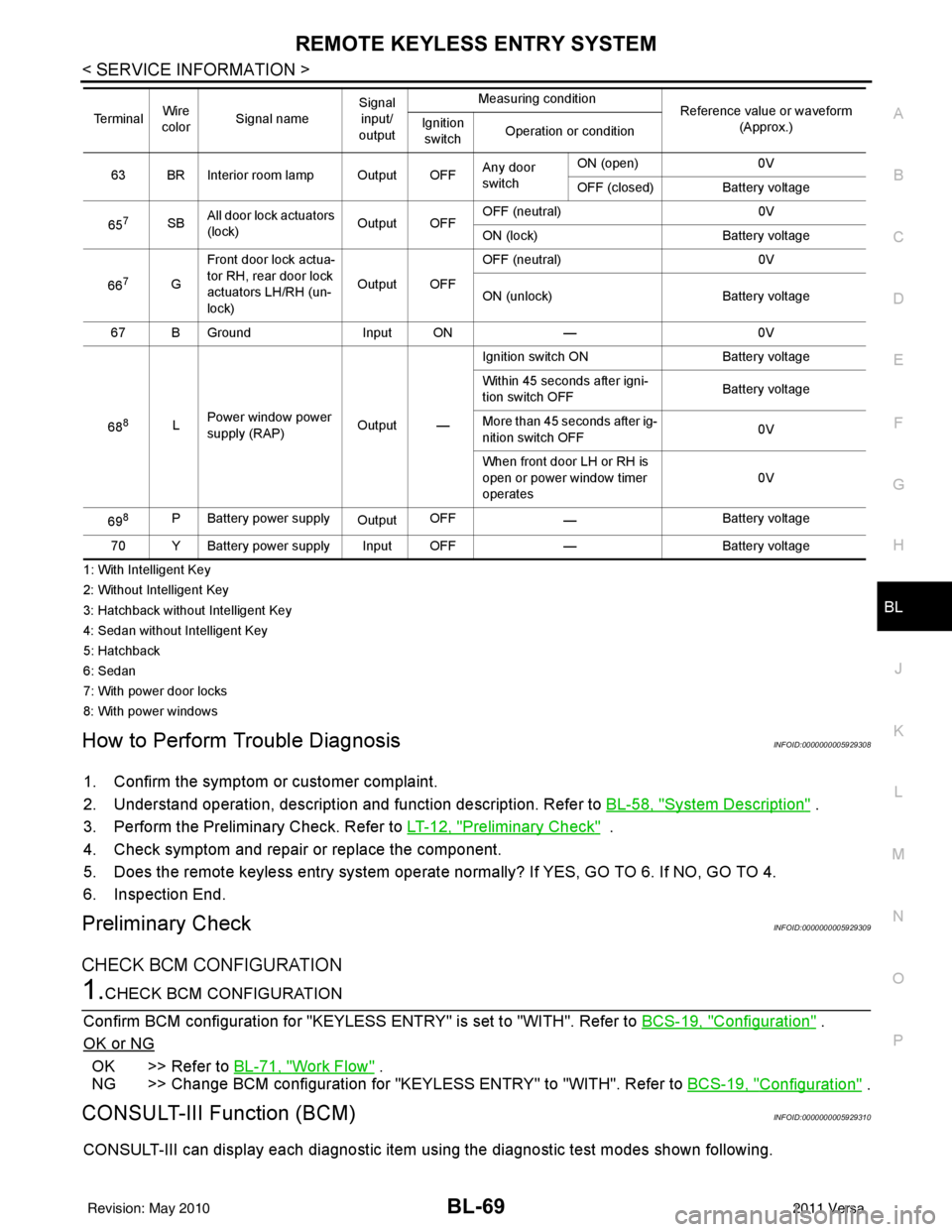
1: With Intelligent Key
2: Without Intelligent Key
3: Hatchback without Intelligent Key
4: Sedan without Intelligent Key
5: Hatchback
6: Sedan
7: With power door locks
8: With power windows
How to Perform Trouble DiagnosisINFOID:0000000005929308
1. Confirm the symptom or customer complaint.
2. Understand operation, description and function description. Refer to BL-58, "
System Description" .
3. Perform the Preliminary Check. Refer to LT-12, "
Preliminary Check" .
4. Check symptom and repair or replace the component.
5. Does the remote keyless entry system operate normally? If YES, GO TO 6. If NO, GO TO 4.
6. Inspection End.
Preliminary CheckINFOID:0000000005929309
CHECK BCM CONFIGURATION
1.CHECK BCM CONFIGURATION
Confirm BCM configuration for "KEYLESS ENTRY" is set to "WITH". Refer to BCS-19, "
Configuration" .
OK or NG
OK >> Refer to BL-71, "Work Flow" .
NG >> Change BCM configuration for "KEYLESS ENTRY" to "WITH". Refer to BCS-19, "
Configuration" .
CONSULT-III Function (BCM)INFOID:0000000005929310
CONSULT-III can display each diagnostic item using the diagnostic test modes shown following.
63 BR Interior room lamp Output OFFAny door
switchON (open)
0V
OFF (closed) Battery voltage
65
7SB All door lock actuators
(lock) Output OFFOFF (neutral)
0V
ON (lock) Battery voltage
66
7G Front door lock actua-
tor RH, rear door lock
actuators LH/RH (un-
lock) Output OFFOFF (neutral)
0V
ON (unlock) Battery voltage
67 B Ground Input ON—0V
68
8L Power window power
supply (RAP)
Output —Ignition switch ON
Battery voltage
Within 45 seconds after igni-
tion switch OFF Battery voltage
More than 45 seconds after ig-
nition switch OFF 0V
When front door LH or RH is
open or power window timer
operates 0V
69
8P Battery power supply OutputOFF
— Battery voltage
70 Y Battery power supply Input OFF —Battery voltage
Te r m i n a l
Wire
color Signal name Signal
input/
output Measuring condition
Reference value or waveform
(Approx.)
Ignition
switch Operation or condition
Revision: May 2010
2011 Versa
Page 582 of 3787

BL-72
< SERVICE INFORMATION >
REMOTE KEYLESS ENTRY SYSTEM
Keyfob Battery and Function Check
INFOID:0000000005929313
1.CHECK KEYFOB FUNCTION
With CONSULT-III
Check keyfob function in “DATA MONITOR” mode with CONSULT-III. When pushing each button of keyfob,
the corresponding monitor item should be turned as follows.
Without CONSULT-III
Door lock does not function with keyfob.
(Power door lock system is “OK”.) 1. Check keyfob function. (Lock)
NOTE:
If the result of keyfob function check with CONSULT-III is OK, key-
fob is not malfunctioning.
BL-822. Replace keyfob. Refer to ID Code Entry Procedure.
BL-83
3. Check door switch (hatchback).BL-74
4. Check door switch (sedan).BL-76
5. Replace BCM.BCS-19
Door unlock does not function with keyfob
(Power door lock system is “OK”)1. Check keyfob function. (Unlock)
BL-82
2. Replace keyfob. Refer to ID Code Entry Procedure.
NOTE:
If the result of keyfob function check with CONSULT-III is OK, key-
fob is not malfunctioning.BL-83
3. Replace BCM.
BCS-19
Hazard reminder does not activate properly when
pressing lock or unlock button of keyfob.1. Check hazard reminder mode.*
*: Hazard reminder mode can be changed.
First check the hazard reminder setting.
BL-69
2. Check hazard function.
BL-79
3. Replace BCM.BCS-19
Panic alarm does not activate when panic alarm but-
ton is continuously pressed.1. Check panic alarm mode.*
*: Panic alarm mode can be changed.
First check the panic alarm setting.
BL-69
2. Check keyfob battery and function.
NOTE:
If the result of keyfob function check with CONSULT-III is OK, key-
fob is not malfunctioning.BL-72
3. Check horn function.
BL-79
4. Check key switch.BL-78
5. Replace keyfob. Refer to ID Code Entry Procedure.BL-83
6. Replace BCM.BCS-19
Auto door lock operation does not activate properly.
(All other remote keyless entry system functions are
OK.)1. Check auto door lock operation mode.*
*: Auto door lock operation mode can be changed.
First check the auto door lock operation setting.
BL-69
2. Replace BCM.
BCS-19
Interior lamp operation does not activate properly.1. Check interior lamp operation.
BL-802. Replace BCM.BCS-19
SymptomDiagnoses/service procedureReference
page
Condition Monitor item
Pushing LOCK KEYLESS LOCK: ON
Pushing UNLOCK KEYLESS UNLOCK: ON
Pushing PANIC KEYLESS PANIC: ON
Revision: May 2010 2011 Versa
Page 598 of 3787
BL-88
< SERVICE INFORMATION >
INTELLIGENT KEY SYSTEM
System Description
INFOID:0000000005929328
• The Intelligent Key system is a system that makes it possible to lock and unlock the door locks (door lock/
unlock function), and start the engine (engine start func tion) by carrying around the Intelligent Key (without
some key operation), which operates based on the results of electronic ID verification using two-way com-
munications between the Intelligent Key and the vehicle (Intelligent Key unit).
• Vehicles equipped with a manual transmission include a key interlock solenoid located in the steering col- umn to prevent accidental shut-off of the ignition sw itch and locking of the steering wheel during driving con-
dition when the vehicle is moving.
CAUTION:
The driver should always carry the Intelligent Key
• Operation of the remote controller buttons on the Inte lligent Key also provides the same functions as the
remote control entry system. (Remote keyless entry functions)
• If an action that does not meet the operating conditions of the Intelligent Key system is taken, the buzzer
goes off to inform the driver. (Warning chime functions)
• When a door lock is locked or unlocked with request switch or remote controller button operation, the hazard
lamps flash and the buzzer (outside vehicle) sounds (Hazard and buzzer reminder function).
• Even if the Intelligent Key battery is completely discharged, the door locks can be locked and unlocked and the engine started with the mechanical key built into the Intelligent Key.
• The settings for each function can be changed with the CONSULT-III.
• If an Intelligent Key is lost, a new Intelligent Key can be registered. A maximum of 4 Intelligent Keys can be registered.
• It has been made possible to diagnose the system and r egister an Intelligent Key with the CONSULT-III.
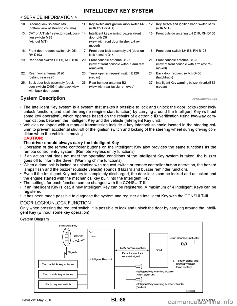
DOOR LOCK/UNLOCK FUNCTION
Only when pressing the request switch, it is possible to lock and unlock the door by carrying around the Intelli-
gent Key (without some key operation).
System Diagram
10. Steering lock solenoid M6
(bottom view of steering column) 11. Key switch and ignition knob switch M73
(with CVT or A/T) 12. Key switch and ignition knob switch M73
(with M/T)
13. CVT or A/T shift selector (park posi- tion switch) M38
(without M/T) 14. Intelligent key warning buzzer (front
door LH) D6
(view with front door finisher LH re-
moved) 15. Front outside antenna LH D10, RH D106
16. Front door request switch LH D5, RH D103 17. Front door lock assembly LH (door un-
lock sensor) D14 18. Front door switch LH B8, RH B108
19. Rear door switch LH B6, RH B116 20. Front console antenna B125 (view of front console without arm rest
removed)21. Front console antenna B125
(view of front console with arm rest re-
moved)
22. Rear floor antenna B126 (behind rear seat) 23. Trunk opener request switch B129
(sedan) 24. Back door request switch D406
(hatchback)
25. Back door lock assembly (back door switch) D405 (hatchback view
with back door open) 26. Rear bumper antenna B2
(view with rear fascia removed) 27. Intelligent Key warn
ing buzzer (trunk) B32
(sedan)
LIIA2926E
Revision: May 2010 2011 Versa
Page 605 of 3787

INTELLIGENT KEY SYSTEMBL-95
< SERVICE INFORMATION >
C
DE
F
G H
J
K L
M A
B
BL
N
O P
CHANGE SETTINGS FUNCTION
The settings for each function c an be changed with the CONSULT-III.
Changing Settings Using CONSULT-III
The settings for the Intelligent Key system func tions can be changed using CONSULT-III (WORK SUPPORT).
Refer to BL-117, "
CONSULT-III Application Item".
NOTE:
Once a function setting is changed, it will remain effective even if the battery is disconnected.
INTELLIGENT KEY REGISTRATION
Intelligent Key-ID registration is performed using the CONSULT-III.
CAUTION:
• After a new Intelligent Key-ID is registered, be sure to check the function.
• When registering an additional Intelligent Key-ID , take any Intelligent Keys already registered and
Intelligent Keys for any other vehicles out of the vehicle before starting.
CONSULT-III can be used to check and delete Intelligent Key-IDs.
For further information, see the CONS ULT-III Operation Manual NATS.
STEERING LOCK SOLENOID REGISTRATION
Steering Lock Solenoid ID Registration
CAUTION:
• The method for registering a steering lock solenoid ID depends on the status of the steering lock
solenoid and Intelligent Key unit (new or old unit).
• After registration is completed, press ignition switch with an Intelligent Key in the vehicle so that it can be turned, and confirm that it cannot be turned even when ignition sw itch is pressed without an
Intelligent Key in the vehicle.
For further information, see the CONSULT-III Operation Manual NATS-IVIS/NVIS.
CAN Communication System DescriptionINFOID:0000000005929329
Refer to LAN-7.
Warning and alarm functions
Intelligent Key
Key switch
Ignition knob switch
Ignition switch ACC position input signal
Ignition switch ON position input signal
Door switch
Door request switch
Inside key antenna
Outside key antenna (Driver, Passenger)
Outside key antenna (rear bumper)
Intelligent Key warning buzzer(s)
Intelligent Key unit
CAN communication system
BCM
Warning lamp
Warning chime (combination meter)
Ignition switch warning chime × ××××× ×
Ignition key warning chime
(When mechanical key used) ×××
×××
OFF position warning chime For internal
××× ××××××
For external ×××× ×××××
Take away warning chime Right after door is
closed
××× × × ×××××
Any door is open ××× × × ××××
Take away from
window ××× × × ××××××
Door lock operation warning chime ×××××××××
Intelligent Key low battery warning ×××× ××
Revision: May 2010 2011 Versa
Page 625 of 3787

INTELLIGENT KEY SYSTEMBL-115
< SERVICE INFORMATION >
C
DE
F
G H
J
K L
M A
B
BL
N
O P
1: With Intelligent Key
2: Without Intelligent Key
3: Hatchback without Intelligent Key
4: Sedan without Intelligent Key
5: Hatchback
6: Sedan
7: With power door locks
8: With power windows
Trouble Diagnosis ProcedureINFOID:0000000005929337
PRELIMINARY CHECK
1.GET SYMPTOMS
Listen to customer c oncerns. (Get symptoms)
NOTE:
If customer reports a “No start” condition, request all Intelligent Keys to be brought to the dealer in case of
Intelligent Key system malfunction.
Intelligent Key or mechanical key service request>>For further information, refer to CONSULT-III operation
manual.
Malfunctions>>GO TO 2
2.CHECK BCM CONFIGURATION
Confirm BCM configuration for "I- KEY" is set to "WITH". Refer to BCS-19, "
Configuration".
OK or NG
OK >> GO TO 3
NG >> Change BCM configuration for "I-KEY" to "WITH". Refer to BCS-19, "
Configuration".
3.START ENGINE WITH INTELLIGENT KEY
Check if the engine could be started by all registered Intelligent Keys.
63 BR Interior room lamp Output OFF Any door
switchON (open)
0V
OFF (closed) Battery voltage
65
7SB All door lock actuators
(lock) Output OFFOFF (neutral)
0V
ON (lock) Battery voltage
66
7G Front door lock actua-
tor RH, rear door lock
actuators LH/RH (un-
lock) Output OFFOFF (neutral)
0V
ON (unlock) Battery voltage
67 B Ground Input ON—0V
68
8L Power window power
supply (RAP)
Output —Ignition switch ON
Battery voltage
Within 45 seconds after igni-
tion switch OFF Battery voltage
More than 45 seconds after ig-
nition switch OFF 0V
When front door LH or RH is
open or power window timer
operates 0V
69
8P Battery power supply OutputOFF
— Battery voltage
70 Y Battery power supply Input OFF —Battery voltage
Te r m i n a l
Wire
color Signal name Signal
input/
output Measuring condition
Reference value or waveform
(Approx.)
Ignition
switch Operation or condition
Revision: May 2010
2011 Versa
Page 629 of 3787

INTELLIGENT KEY SYSTEMBL-119
< SERVICE INFORMATION >
C
DE
F
G H
J
K L
M A
B
BL
N
O P
Trouble Diagnosis Symptom ChartINFOID:0000000005929340
KEY WARNING LAMP (GREEN) ILLUMINATES
NOTE:
Monitor item Description
CONFIRM KEY FOB ID It can be checked whether Intelligent Key ID code is registered or not in this mode.
TAKE OUT FROM WINDOW
WARN Take away warning chime (from window) mode can be changed to operate (ON) or not operate
(OFF) with this mode. The operation mode will be changed when “CHANGE SETT” on CONSULT-
III screen is touched.
LOW BAT OF KEY FOB WARN Intelligent Key low battery warning mode can be changed to operate (ON) or not operate (OFF)
with this mode. The operation mode will be changed when “CHANGE
SETT” on CONSULT-III
screen is touched.
ANSWER BACK FUNCTION Buzzer reminder function mode by Intelligent button can be changed to operate (ON) or not oper-
ate (OFF) with this mode. The operation mode will be changed when “CHANGE SETT” on CON-
SULT-III screen is touched.
SELECTIVE UNLOCK FUNC-
TION Selective unlock function mode can be changed to operate (ON) or not operate (OFF) with this
mode. The operation mode will be changed when “CHANGE SETT” on CONSULT-III screen is
touched.
ANTI KEY LOCK IN FUNCTION Key reminder function mode can be changed to operate (ON) or not operate (OFF) with this mode.
The operation mode will be changed when “CHANGE SETT” on CONSULT-III screen is touched.
HORN WITH KEYLESS LOCK Horn reminder function mode by Intelligent Key remote control button can be changed to operate
(ON) or not operate (OFF) with this mode. The operation mode will be changed when “CHANGE
SETT” on CONSULT-III screen is touched.
HAZARD ANSWER BACK Hazard reminder function mode can be selected from the following with this mode. The operation
mode will be changed when “CHANGE SE
TT” on CONSULT-III screen is touched.
• LOCK ONLY: Door lock operation only
• UNLOCK ONLY: Door unlock operation only
• LOCK/UNLOCK: Lock/Unlock operation
• OFF: Non-operation
ANSWER BACK WITH I-KEY
LOCK Buzzer reminder function (lock operation) mode by door request switch (driver side, passenger
side and back door side) can be selected from the following with this mode. The operation mode
will be changed when “
CHANGE SETT” on CONSULT- III screen is touched.
• BUZZER: Sound buzzer
• OFF: Non-operation
ANSWER BACK WITH I-KEY UN-
LOCK Buzzer reminder function (unlock operation) mode by door request switch can be changed to op-
erate (ON) or not operate (OFF) with this mode.
AUTO RELOCK TIMER Auto door lock timer mode can select the following with this mode.
• 1 minute
• OFF: Non-operation
PANIC ALARM DELAY Panic alarm button's pressing time on Intelligent Key remote control button can be selected from
the following with this mode. The operation mode will be changed when “CHANGE SETT” on
CONSULT-III screen is touched.
• 0.5 second
• 1.5 second
• OFF: Non-operation
P/W DOWN DELAY Unlock button's pressing time on Intelligent Key remote control button can be selected from the
following with this mode. The operation mode will be changed when “CHANGE SETT” on CON-
SULT-III screen is touched.
• 3 seconds
• 5 seconds
• OFF: Non-operation
ENGINE START BY I-KEY Engine start function mode can be changed to operate (ON) or not operate (OFF) with this mode.
The operation mode will be changed when “CHANGE SETT” on CONSULT-III screen is touched.
LOCK/UNLOCK BY I-KEY Door lock/unlock function by door request switch (driver side, passenger side and back door side)
mode can be changed to operate (ON) or not operate (OFF) with this mode. The operation mode
will be changed when “
CHANGE SETT” on CONSULT- III screen is touched.
Revision: May 2010 2011 Versa
Page 2733 of 3787
SERVICE INFORMATION FOR ELECTRICAL INCIDENTGI-29
< SERVICE INFORMATION >
C
DE
F
G H
I
J
K L
M B
GI
N
O P
• Close the relay and probe at the solenoid. voltage; open is further down the circuit than the solenoid.
no voltage; open is between relay and solenoid (point C).
Any powered circuit can be diagnosed using the approach in the previous example.
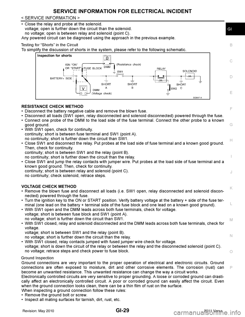
Testing for “Shorts” in the Circuit
To simplify the discussion of shorts in the system, please refer to the following schematic.
RESISTANCE CHECK METHOD
• Disconnect the battery negative cable and remove the blown fuse.
• Disconnect all loads (SW1 open, relay disconnected and solenoid disconnected) powered through the fuse.
• Connect one probe of the DMM to the load side of the fuse terminal. Connect the other probe to a known
good ground.
• With SW1 open, check for continuity.
continuity; short is between fuse terminal and SW1 (point A).
no continuity; short is further down the circuit than SW1.
• Close SW1 and disconnect the relay. Put probes at the load side of fuse terminal and a known good ground.
Then, check for continuity.
continuity; short is between SW1 and the relay (point B).
no continuity; short is further down the circuit than the relay.
• Close SW1 and jump the relay contacts with jumper wir e. Put probes at the load side of fuse terminal and a
known good ground. Then, check for continuity.
continuity; short is between relay and solenoid (point C).
no continuity; check solenoid, retrace steps.
VOLTAGE CHECK METHOD
• Remove the blown fuse and disconnect all loads (i .e. SW1 open, relay disconnected and solenoid discon-
nected) powered through the fuse.
• Turn the ignition key to the ON or START position. Veri fy battery voltage at the battery + side of the fuse ter-
minal (one lead on the battery + terminal side of the fuse block and one lead on a known good ground).
• With SW1 open and the DMM leads across both fuse terminals, check for voltage.
voltage; short is between fuse block and SW1 (point A).
no voltage; short is further down the circuit than SW1.
• With SW1 closed, relay and solenoid disconnected and the DMM leads across both fuse terminals, check for voltage.
voltage; short is between SW1 and the relay (point B).
no voltage; short is further down the circuit than the relay.
• With SW1 closed, relay contacts jumped with fused jumper wire check for voltage.
voltage; short is down the circuit of the relay or between the relay and the disconnected solenoid (point C).
no voltage; retrace steps and check power to fuse block.
Ground Inspection
Ground connections are very important to the proper oper ation of electrical and electronic circuits. Ground
connections are often exposed to moisture, dirt and other corrosive elements. The corrosion (rust) can
become an unwanted resistance. This unwanted resistance can change the way a circuit works.
Electronically controlled circuits are very sensitive to proper grounding. A loose or corroded ground can drasti-
cally affect an electronically controlled circuit. A poor or corroded ground can easily affect the circuit. Even
when the ground connection looks clean, there can be a thin film of rust on the surface.
When inspecting a ground connection follow these rules:
• Remove the ground bolt or screw.
• Inspect all mating surfaces for tarnish, dirt, rust, etc.
SGI847-A
Revision: May 2010 2011 Versa
Page 3128 of 3787

LT-96
< SERVICE INFORMATION >
INTERIOR ROOM LAMP
• to BCM terminal 7
• through front door lock assembly LH (key cylinder switch) terminal 5
• through front door lock assembly LH (key cylinder switch) terminal 4
• through grounds M57 and M61.
At the time the front door LH is opened, the BCM detects the front door LH is unlocked. It determines that the
interior room lamp timer operation conditions are met, and interior room lamp ON for 30 seconds.
When the key is in ignition key cylinder (key switch ON ), or ignition knob switch is pushed, power is supplied
• through key switch and ignition knob switch terminal 1
• to BCM terminal 37, or
• through key switch and ignition knob switch terminal 3
• to Intelligent Key unit terminal 27.
When the key is removed from key switch (key switch OFF), power supply to BCM terminal 37 is terminated.
When the ignition knob switch is released, power supply to intelligent key unit is terminated. The BCM detects
that the key has been removed, determines that interior room lamp timer conditions are met, and turns room
lamp ON for 30 seconds.
When the front door LH opens → closes, and key is not inserted in key switch (or ignition knob switch is
released), BCM terminal 47 changes between 0V (door open) → 12V (door closed). BCM determines that
conditions for room lamp operation are met, and turns room lamp ON for 30 seconds.
Interior room lamp timer control is canceled under the following conditions:
• Front door LH is locked (with keyfob, front door lock assembly LH (key cylinder switch) or door lock/unlock switch).
• Front door LH is opened (front door switch LH).
• Ignition switch ON.
INTERIOR LAMP BATTERY SAVER CONTROL
If an interior room lamp is left ON, it will not be turned OFF even when door is closed.
BCM turns off interior lamp automatically to save battery 15 minutes after ignition switch is turned off.
After lamps are turned OFF by the battery saver system, the lamps illuminate again when
• front door lock assembly LH (key cylinder switch) is locked or unlocked
• door is opened or closed
• key is removed from ignition key cylinder or inserted in ignition key cylinder, or the ignition knob switch is pushed or released.
Interior lamp battery saver control time period can be changed by the function setting of CONSULT-III.
Revision: May 2010 2011 Versa