wiper NISSAN TIIDA 2011 Service Repair Manual
[x] Cancel search | Manufacturer: NISSAN, Model Year: 2011, Model line: TIIDA, Model: NISSAN TIIDA 2011Pages: 3787, PDF Size: 78.35 MB
Page 1 of 3787
-1
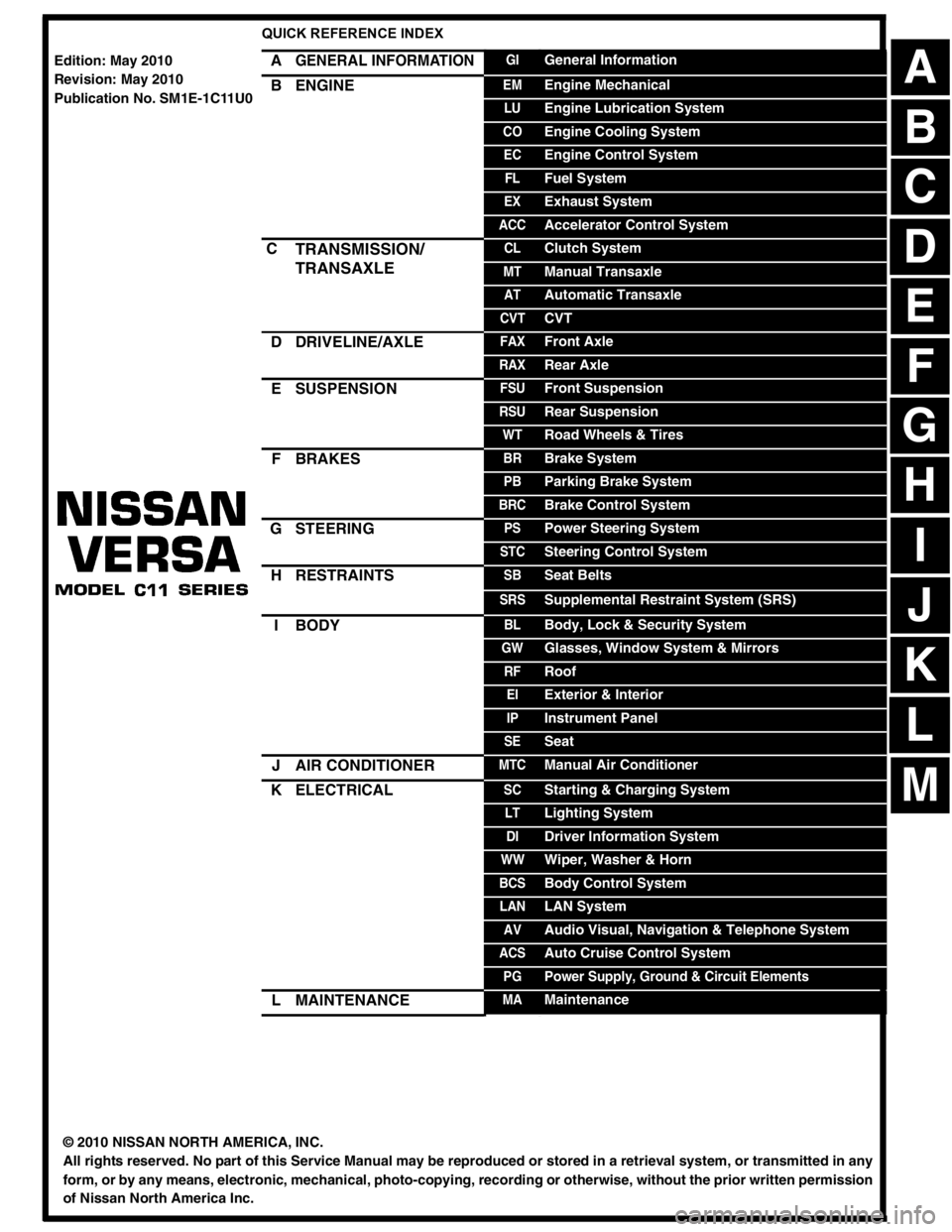
QUICK REFERENCE INDEX
AGENERAL INFORMATIONGIGeneral Information
BENGINEEMEngine Mechanical
LUEngine Lubrication System
COEngine Cooling System
ECEngine Control System
FLFuel System
EXExhaust System
ACCAccelerator Control System
CTRANSMISSION/
TRANSAXLECLClutch System
MTManual Transaxle
ATAutomatic Transaxle
CVTCVT
DDRIVELINE/AXLEFAXFront Axle
RAXRear Axle
ESUSPENSIONFSUFront Suspension
RSURear Suspension
WTRoad Wheels & Tires
FBRAKESBRBrake System
PBParking Brake System
BRCBrake Control System
GSTEERINGPSPower Steering System
STCSteering Control System
HRESTRAINTSSBSeat Belts
SRSSupplemental Restraint System (SRS)
IBODYBLBody, Lock & Security System
GWGlasses, Window System & Mirrors
RFRoof
EIExterior & Interior
IPInstrument Panel
SESeat
JAIR CONDITIONERMTCManual Air Conditioner
KELECTRICALSCStarting & Charging System
LTLighting System
DIDriver Information System
WWWiper, Washer & Horn
BCSBody Control System
LANLAN System
AVAudio Visual, Navigation & Telephone System
ACSAuto Cruise Control System
PGPower Supply, Ground & Circuit Elements
LMAINTENANCEMAMaintenance
Edition: May 2010
Revision: May 2010
Publication No. SM1E-1C11U0
B
D
© 2010 NISSAN NORTH AMERICA, INC.
All rights reserved. No part of this Service Manual may be reproduced or stored in a retrieval system, or transmitted in any
form, or by any means, electronic, mechanical, photo-copying, recording or otherwise, without the prior written permission
of Nissan North America Inc.
A
C
E
F
G
H
I
J
K
L
M
Page 494 of 3787
BCS-4
< SERVICE INFORMATION >
BCM (BODY CONTROL MODULE)
BCM (BODY CONTROL MODULE)
System DescriptionINFOID:0000000005929255
BCM (body control module) controls the operation of various electrical units installed on the vehicle.
BCM FUNCTION
BCM has a combination switch reading function for reading the operation of combination switches (light, wiper,
washer, turn signal) in addition to the function for cont rolling the operation of various electrical components.
Also, it functions as an interface that receives signal s from the front air control, and sends signals to ECM
using CAN communication.
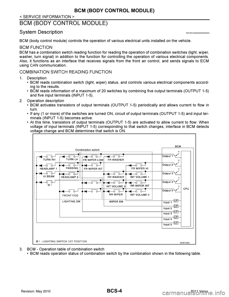
COMBINATION SWITCH READING FUNCTION
1. Description • BCM reads combination switch (light, wiper) status, and controls various electrical components accord-
ing to the results.
• BCM reads information of a maximum of 20 switches by combining five output terminals (OUTPUT 1-5)
and five input terminals (INPUT 1-5).
2. Operation description • BCM activates transistors of output terminals (OUTPU T 1-5) periodically and allows current to flow in
turn.
• If any (1 or more) of the switches are turned ON, circuit of output terminals (OUTPUT 1-5) and input ter- minals (INPUT 1-5) becomes active.
• At this time, transistors of output terminals (OUTPUT 1-5) are activated to allow current to flow. When
voltage of input terminals (INPUT 1-5) corresponding to that switch changes, interface in BCM detects
voltage change and BCM determines that switch is ON.
3. BCM - Operation table of combination switch • BCM reads operation status of combination switch by the combination shown in the following table.
SKIB7592E
Revision: May 2010 2011 Versa
Page 497 of 3787
BCM (BODY CONTROL MODULE)BCS-7
< SERVICE INFORMATION >
C
DE
F
G H
I
J
L
M A
B
BCS
N
O P
• When CAN communication operation is detected, it switches to CAN communication status.
• When a state of the following switches changes , it switches to CAN communication state:
- Ignition switch
- Key switch (without Intelligent Key)
- Key switch and ignition knob switch (with Intelligent Key)
- Hazard switch
- Door lock/unlock switch (with power door locks)
- Front door switch (LH, RH)
- Rear door switch (LH, RH)
- Back door lock assembly (Hatchback)
- Trunk key cylinder switch (Sedan)
- Trunk lamp switch and trunk release solenoid (Sedan)
- Combination switch (passing, lighting switch 1st position, front fog lamp)
- Keyfob (lock/unlock signal) (with power door locks)
- Front door key cylinder switch LH
• When control performed only by BCM is required by switch, it shifts to CAN communication inactive mode.
• Status of combination switch reading function is changed.
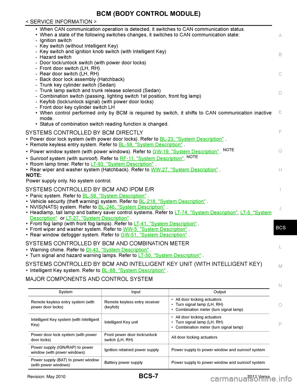
SYSTEMS CONTROLLED BY BCM DIRECTLY
• Power door lock system (with power door locks). Refer to BL-23, "System Description" .
• Remote keyless entry system. Refer to BL-58, "
System Description" .
• Power window system (with power windows). Refer to GW-19, "
System Description" . NOTE
• Sunroof system (with sunroof). Refer to RF-11, "System Description". NOTE
• Room lamp timer. Refer to LT-93, "System Description" .
• Rear wiper and washer system (Hatchback). Refer to WW-27, "
System Description" .
NOTE:
Power supply only. No system control.
SYSTEMS CONTROLLED BY BCM AND IPDM E/R
• Panic system. Refer to BL-58, "System Description" .
• Vehicle security (theft warning) system. Refer to BL-218, "
System Description" .
• NVIS(NATS) system. Refer to BL-246, "
System Description" .
• Headlamp, tail lamp and battery saver control systems. Refer to LT-74, "
System Description", LT- 5 , "System
Description" or LT-27, "System Description" .
• Front fog lamp (with front fog lamps). Refer to LT-41, "
System Description" .
• Front wiper and washer system. Refer to WW-5, "
System Description" .
• Rear window defogger system. Refer to GW-51, "
System Description" .
SYSTEMS CONTROLLED BY BCM AND COMBINATION METER
• Warning chime. Refer to DI-43, "System Description" .
• Turn signal and hazard warning lamps. Refer to LT-50, "
System Description" .
SYSTEMS CONTROLLED BY BCM AND INTELLIGENT KEY UNIT (WITH INTELLIGENT KEY)
• Intelligent Key system. Refer to BL-88, "System Description" .
MAJOR COMPONENTS AND CONTROL SYSTEM
System Input Output
Remote keyless entry system (with
power door locks) Remote keyless entry receiver
(keyfob)• All door locking actuators
• Turn signal lamp (LH, RH)
• Combination meter (turn signal lamp)
Intelligent Key system (with Intelligent
Key) Intelligent Key unit• All door locking actuators
• Turn signal lamp (LH, RH)
• Combination meter (turn signal lamp)
Power door lock system (with power
door locks) Front power door lock/unlock
switch (LH, RH)
All door locking actuators
Power supply (IGN /RAP) to power
window (with power windows) Ignition retained power supply Power supply to power window and sunroof system
Power supply (BAT) to power window
(with power windows) Battery power supply
Power supply to power window and sunroof system
Revision: May 2010 2011 Versa
Page 498 of 3787

BCS-8
< SERVICE INFORMATION >
BCM (BODY CONTROL MODULE)
CAN Communication System Description
INFOID:0000000005929256
Refer to LAN-7, "System Description".
Panic alarm •Key switch
•KeyfobIPDM E/R
Vehicle security system • All door switches
•Keyfob
• Door lock/unlock switch
• Trunk key cylinder switch (Se-
dan)
• Front door key cylinder switch LH • IPDM/ER
• Security indicator lamp
Battery save r control • Ignition switch
• Combination switch
IPDM E/R
Headlamp Combination switch IPDM E/R
Tail lamp Combination switchIPDM E/R
Front fog lamp (with front fog lamps) Combination switch IPDM E/R
Turn signal lamp Combination switch• Turn signal lamp
• Combination meter
Hazard lamp Hazard switch• Turn signal lamp
• Combination meter
Room lamp timer •Key switch
•Keyfob
• Main power window and door
lock/unlock switch
• Front door switch LH
• All door switch Interior room lamp
Back door switch signal (Hatchback) Back door lock assembly Luggage room lamp
Back door lock signal (Hatchback) Back door lock assembly Back door opener
Trunk lamp switch signal (Sedan) Trunk lamp switch and trunk re-
lease solenoidLuggage room lamp
Trunk lid opener signal (Sedan) Trunk lamp switch and trunk re-
lease solenoid
Trunk lid opener
Key warning chime •Key switch
• Front door switch LHCombination meter (warning buzzer)
Light warning chime • Combination switch
•Key switch
• Front door switch LHCombination meter (warning buzzer)
Seat belt warning chime • Seat belt buckle switch LH
• Ignition switch
Combination meter (warning buzzer)
Front wiper and washer system • Combination switch
• Ignition switchIPDM E/R
Rear window defogger Rear window defogger switch IPDM E/R
Rear wiper and washer system
(Hatchback) • Combination switch
• Ignition switch
Rear wiper motor
A/C switch signal Front air controlECM
Blower fan switch signal Front air controlECM
A/C indicator signal Front air controlA/C indicator
Low tire pressure warning system Remote keyless entry receiver Combination meter System
Input Output
Revision: May 2010 2011 Versa
Page 502 of 3787
BCS-12
< SERVICE INFORMATION >
BCM (BODY CONTROL MODULE)
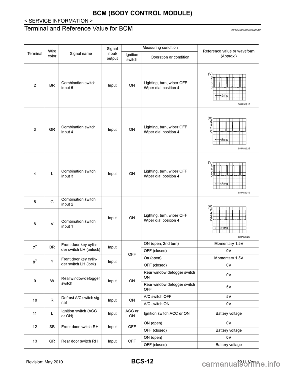
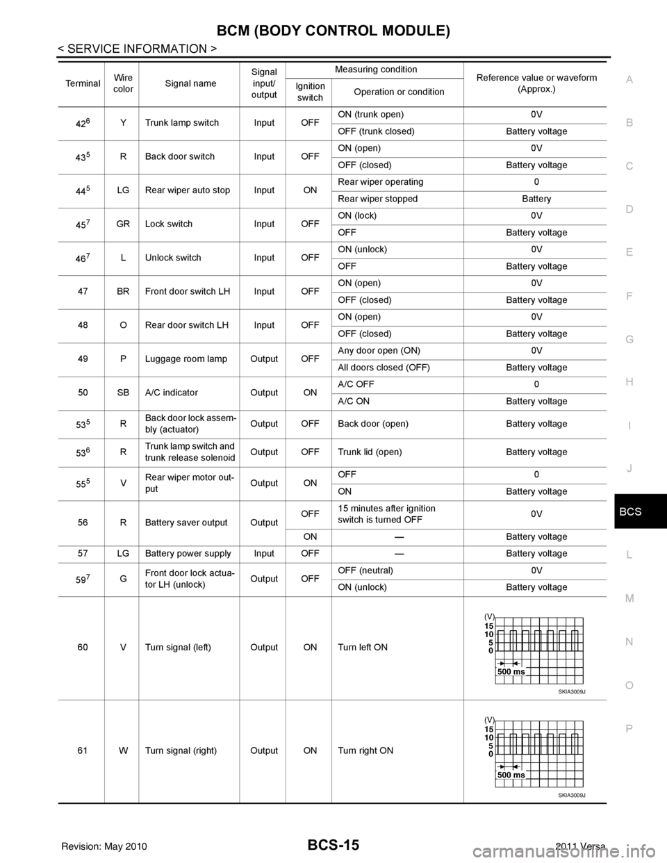
Terminal and Reference Value for BCM
INFOID:0000000005929259
Te r m i n a l Wire
color Signal name Signal
input/
output Measuring condition
Reference value or waveform
(Approx.)
Ignition
switch Operation or condition
2BR Combination switch
input 5
Input ONLighting, turn, wiper OFF
Wiper dial position 4
3GR Combination switch
input 4 Input ONLighting, turn, wiper OFF
Wiper dial position 4
4L Combination switch
input 3
Input ONLighting, turn, wiper OFF
Wiper dial position 4
5G Combination switch
input 2
Input ONLighting, turn, wiper OFF
Wiper dial position 4
6V Combination switch
input 1
7
7BR Front door key cylin-
der switch LH (unlock) Input
OFFON (open, 2nd turn)
Momentary 1.5V
OFF (closed) 0V
8
7Y Front door key cylin-
der switch LH (lock) InputOn (open)
Momentary 1.5V
OFF (closed) 0V
9W Rear window defogger
switch Input ONRear window defogger switch
ON
0V
Rear window defogger switch
OFF 5V
10 R Defrost A/C switch sig-
nal
Input ONA/C switch OFF
5V
A/C switch ON 0V
11 L Ignition switch (ACC
or ON) InputACC or
ON Ignition switch ACC or ON
Battery voltage
12 SB Front door switch RH Input OFF ON (open)
0V
OFF (closed) Battery voltage
13 GR Rear door switch RH Input OFF ON (open)
0V
OFF (closed) Battery voltage
SKIA5291E
SKIA5292E
SKIA5291E
SKIA5292E
Revision: May 2010 2011 Versa
Page 504 of 3787
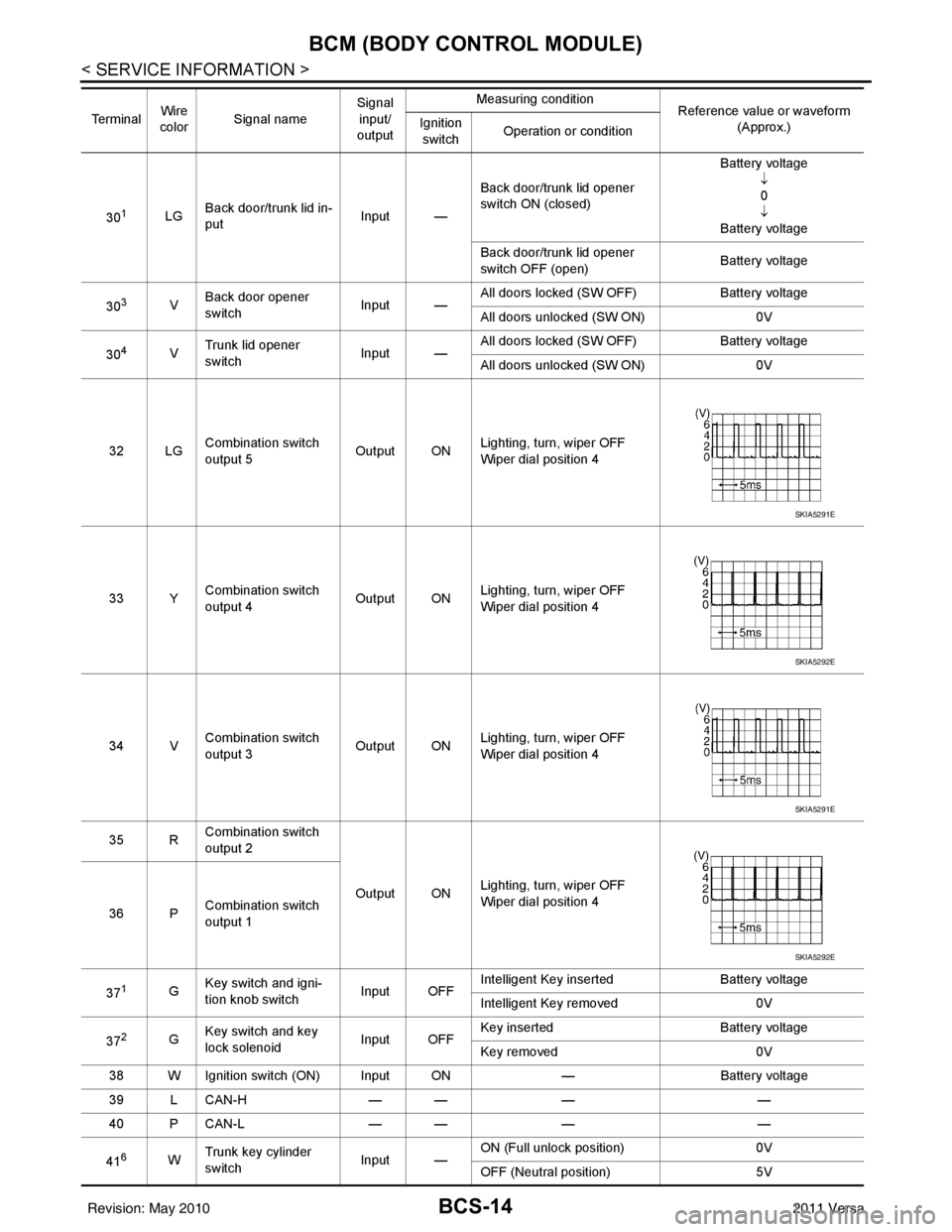
BCS-14
< SERVICE INFORMATION >
BCM (BODY CONTROL MODULE)
301LGBack door/trunk lid in-
put Input —Back door/trunk lid opener
switch ON (closed) Battery voltage
↓0
↓
Battery voltage
Back door/trunk lid opener
switch OFF (open) Battery voltage
30
3V Back door opener
switch
Input —All doors locked (SW OFF)
Battery voltage
All doors unlocked (SW ON) 0V
30
4V Trunk lid opener
switch
Input —All doors locked (SW OFF)
Battery voltage
All doors unlocked (SW ON) 0V
32 LG Combination switch
output 5 Output ONLighting, turn, wiper OFF
Wiper dial position 4
33 Y Combination switch
output 4 Output ON
Lighting, turn, wiper OFF
Wiper dial position 4
34 V Combination switch
output 3
Output ONLighting, turn, wiper OFF
Wiper dial position 4
35 R Combination switch
output 2
Output ONLighting, turn, wiper OFF
Wiper dial position 4
36 P Combination switch
output 1
37
1G Key switch and igni-
tion knob switch Input OFFIntelligent Key inserted
Battery voltage
Intelligent Key removed 0V
37
2G Key switch and key
lock solenoid Input OFFKey inserted
Battery voltage
Key removed 0V
38 W Ignition switch (ON) Input ON —Battery voltage
39 L CAN-H — —— —
40 P CAN-L — —— —
41
6W Trunk key cylinder
switch
Input —ON (Full unlock position)
0V
OFF (Neutral position) 5V
Te r m i n a l
Wire
color Signal name Signal
input/
output Measuring condition
Reference value or waveform
(Approx.)
Ignition
switch Operation or condition
SKIA5291E
SKIA5292E
SKIA5291E
SKIA5292E
Revision: May 2010
2011 Versa
Page 505 of 3787
BCM (BODY CONTROL MODULE)BCS-15
< SERVICE INFORMATION >
C
DE
F
G H
I
J
L
M A
B
BCS
N
O P
426Y Trunk lamp switch Input OFF ON (trunk open)
0V
OFF (trunk closed) Battery voltage
43
5R Back door switch Input OFF ON (open) 0V
OFF (closed)
Battery voltage
44
5LG Rear wiper auto stop Input ON Rear wiper operating 0
Rear wiper stopped
Battery
45
7GR Lock switch Input OFFON (lock)
0V
OFF Battery voltage
46
7L Unlock switch Input OFFON (unlock)
0V
OFF Battery voltage
47 BR Front door switch LH Input OFF ON (open)
0V
OFF (closed) Battery voltage
48 O Rear door switch LH Input OFF ON (open)
0V
OFF (closed) Battery voltage
49 P Luggage room lamp Output OFF Any door open (ON)
0V
All doors closed (OFF) Battery voltage
50 SB A/C indicator Output ONA/C OFF
0
A/C ON Battery voltage
53
5R Back door lock assem-
bly (actuator)
Output OFF Back door (open)
Battery voltage
53
6R Trunk lamp switch and
trunk release solenoid Output OFF Trunk lid (open)
Battery voltage
55
5V Rear wiper motor out-
put
Output ONOFF
0
ON Battery voltage
56 R Battery saver output Output OFF
15 minutes after ignition
switch is turned OFF 0V
ON — Battery voltage
57 LG Battery power supply Input OFF —Battery voltage
59
7G Front door lock actua-
tor LH (unlock)
Output OFFOFF (neutral)
0V
ON (unlock) Battery voltage
60 V Turn signal (left) Output ON Turn left ON
61 W Turn signal (right) Output ON Turn right ON
Te r m i n a l
Wire
color Signal name Signal
input/
output Measuring condition
Reference value or waveform
(Approx.)
Ignition
switch Operation or condition
SKIA3009J
SKIA3009J
Revision: May 2010
2011 Versa
Page 508 of 3787

BCS-18
< SERVICE INFORMATION >
BCM (BODY CONTROL MODULE)
WORK SUPPORT
Display Item List
CAN Communication Inspection Using CONSULT-III (Self-Diagnosis)INFOID:0000000005929262
1.SELF-DIAGNOSTIC RESULT CHECK
1. Connect CONSULT–III and select “BCM” on “SELECT SYSTEM” screen.
2. Select “BCM” on “SELECT TEST ITEM” screen, and select “SELF-DIAG RESULTS”.
3. Check display content in self-diagnostic results.
System and item CONSULT-III
display Diagnostic test mode (Inspection by part)
WORK
SUPPORT SELF
DIAGNOS- TIC RE-
SULT CAN DIAG
SUPPORT MNTR DATA
MONITOR ECU
IDENTI- FICA-
TION AC-
TIVE
TEST CON-
FIGU-
RATION
BCM BCM×× × × ×
Power door lock sys-
tem DOOR LOCK
×× ×
Rear defogger REAR DEFOG-
GER ××
Warning chime BUZZER ××
Room lamp timer INT LAMP ×× ×
Remote keyless entry
system MULTI REMOTE
ENT
××
×
Headlamp HEAD LAMP×× ×
Wiper WIPER×× ×
Turn signal lamp
Hazard lamp FLASHER
××
Blower fan switch sig-
nal
Air conditioner switch
signal AIR CONDITION-
ER
××
Intelligent Key INTELLIGENT
KEY ×
Combination switch COMB SW ×
NVIS (NATS) IMMU ××
Interior lamp battery
saver BATTERY SAV-
ER
××
×
Back door/Trunk TRUNK ××
Theft alarm THEFT ALARM×× ×
Retained accessory
power control RETAINED PWR
×× ×
Oil pressure swit ch SIGNAL BUFFER ××
Low tire pressure moni-
tor AIR PRESSURE
MONITOR
××
× ×
Panic alarm PANIC ALARM ×
ItemDescription
RESET SETTING VALUE Return a value set with WORK SUPPORT of each system to a default value in factory shipment.
Revision: May 2010 2011 Versa
Page 547 of 3787
POWER DOOR LOCK SYSTEMBL-37
< SERVICE INFORMATION >
C
DE
F
G H
J
K L
M A
B
BL
N
O P
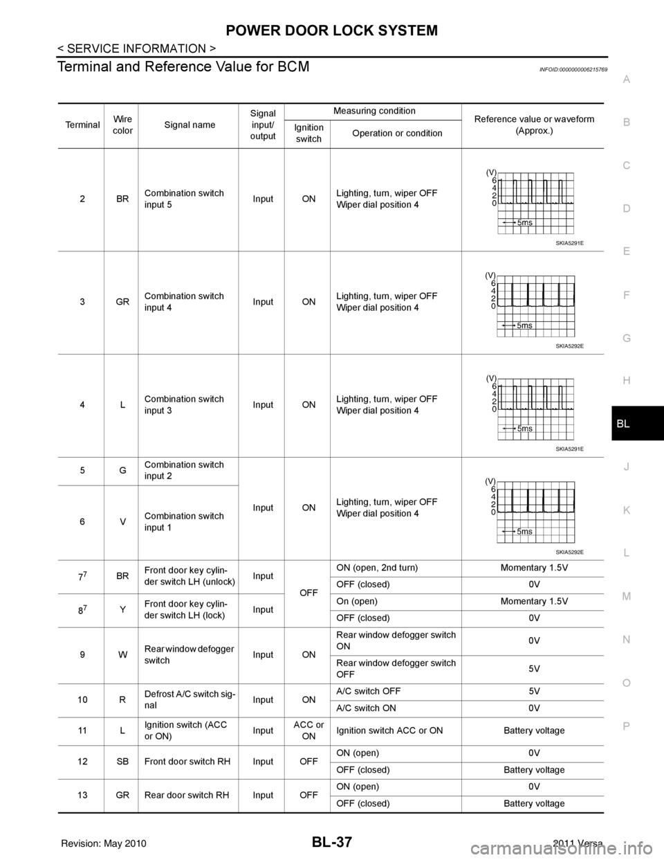
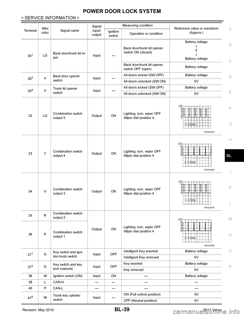
Terminal and Reference Value for BCMINFOID:0000000006215769
Te r m i n a l Wire
color Signal name Signal
input/
output Measuring condition
Reference value or waveform
(Approx.)
Ignition
switch Operation or condition
2BR Combination switch
input 5
Input ONLighting, turn, wiper OFF
Wiper dial position 4
3GR Combination switch
input 4 Input ONLighting, turn, wiper OFF
Wiper dial position 4
4L Combination switch
input 3
Input ONLighting, turn, wiper OFF
Wiper dial position 4
5G Combination switch
input 2
Input ONLighting, turn, wiper OFF
Wiper dial position 4
6V Combination switch
input 1
7
7BR Front door key cylin-
der switch LH (unlock) Input
OFFON (open, 2nd turn)
Momentary 1.5V
OFF (closed) 0V
8
7Y Front door key cylin-
der switch LH (lock) InputOn (open)
Momentary 1.5V
OFF (closed) 0V
9W Rear window defogger
switch Input ONRear window defogger switch
ON
0V
Rear window defogger switch
OFF 5V
10 R Defrost A/C switch sig-
nal
Input ONA/C switch OFF
5V
A/C switch ON 0V
11 L Ignition switch (ACC
or ON) InputACC or
ON Ignition switch ACC or ON
Battery voltage
12 SB Front door switch RH Input OFF ON (open)
0V
OFF (closed) Battery voltage
13 GR Rear door switch RH Input OFF ON (open)
0V
OFF (closed) Battery voltage
SKIA5291E
SKIA5292E
SKIA5291E
SKIA5292E
Revision: May 2010 2011 Versa
Page 549 of 3787
POWER DOOR LOCK SYSTEMBL-39
< SERVICE INFORMATION >
C
DE
F
G H
J
K L
M A
B
BL
N
O P
301LG Back door/trunk lid in-
put Input —Back door/trunk lid opener
switch ON (closed) Battery voltage
↓0
↓
Battery voltage
Back door/trunk lid opener
switch OFF (open) Battery voltage
30
3V Back door opener
switch
Input —All doors locked (SW OFF)
Battery voltage
All doors unlocked (SW ON) 0V
30
4V Trunk lid opener
switch
Input —All doors locked (SW OFF)
Battery voltage
All doors unlocked (SW ON) 0V
32 LG Combination switch
output 5 Output ONLighting, turn, wiper OFF
Wiper dial position 4
33 Y Combination switch
output 4 Output ON
Lighting, turn, wiper OFF
Wiper dial position 4
34 V Combination switch
output 3
Output ONLighting, turn, wiper OFF
Wiper dial position 4
35 R Combination switch
output 2
Output ONLighting, turn, wiper OFF
Wiper dial position 4
36 P Combination switch
output 1
37
1G Key switch and igni-
tion knob switch Input OFFIntelligent Key inserted
Battery voltage
Intelligent Key removed 0V
37
2G Key switch and key
lock solenoid Input OFFKey inserted
Battery voltage
Key removed 0V
38 W Ignition switch (ON) Input ON —Battery voltage
39 L CAN-H — —— —
40 P CAN-L — —— —
41
6W Trunk key cylinder
switch
Input —ON (Full unlock position)
0V
OFF (Neutral position) 5V
Te r m i n a l
Wire
color Signal name Signal
input/
output Measuring condition
Reference value or waveform
(Approx.)
Ignition
switch Operation or condition
SKIA5291E
SKIA5292E
SKIA5291E
SKIA5292E
Revision: May 2010
2011 Versa