steering wheel adjustment NISSAN TITAN 2022 Owners Manual
[x] Cancel search | Manufacturer: NISSAN, Model Year: 2022, Model line: TITAN, Model: NISSAN TITAN 2022Pages: 635, PDF Size: 7.78 MB
Page 201 of 635
3 Pre-driving checks and adjustments
Keys.............................................3-2NISSAN Intelligent Key® .......................3-2
NISSAN Vehicle Immobilizer System
keys..........................................3-4
Doors ...........................................3-4
Locking with key .............................3-5
Locking with inside lock knob ................3-6
Locking with power door lock switch .........3-6
Rear doors (King Cab® models) ............... 3-7
Automatic door locks (if so equipped) ........3-8
Child safety rear door lock (if so
equipped) ....................................3-9
NISSAN Intelligent Key® system ..................3-9
Operating range ............................ 3-10
Door locks/unlocks precaution ...............3-11
NISSAN Intelligent Key® Operation ............3-11
How to use the remote keyless entry
function ..................................... 3-15
Warning signals ............................. 3-18
Troubleshooting guide ......................3-19
Remote Engine Start (if so equipped) ...........3-20
Remote Engine Start operating range .......3-20
Remote starting the vehicle .................3-21
Extending engine run time ..................3-21
Canceling a Remote Engine Start ...........3-21 Conditions the Remote Engine Start will
notwork ....................................
3-22
Hood ........................................... 3-23
Fuel-filler door .................................. 3-23
Gasoline fuel engines .......................3-24
Steering wheel ................................. 3-26
Manual operation (if so equipped) ...........3-26
Automatic operation (if so equipped) ........3-27
Sun visors ...................................... 3-28
Vanity mirrors (if so equipped) ...............3-28
Card holder (driver’s side only) ...............3-29
Mirrors ......................................... 3-29
Manual anti-glare rearview mirror
(if so equipped) .............................. 3-29
Automatic anti-glare rearview mirror
(if so equipped) .............................. 3-29
Outside mirrors ............................. 3-30
Truck box ...................................... 3-34
Tailgate ..................................... 3-34
Tie down hooks ............................. 3-38
Memor
y Seat (if so equipped) ..................3-38
Memory storage function ...................3-39
Entry/exit function .......................... 3-40
System operation ........................... 3-40
Page 226 of 635
Loose Fuel Cap warning
The Loose Fuel Cap warning appears in the
vehicle information display when the fuel-
filler cap is not tightened correctly af ter the
vehicle has been refueled. It may take a few
driving trips for the message to be dis-
played. To turn off the warning, perform the
following:
1. Remove and install the fuel-filler cap aspreviously described as soon as
possible.
2. Tighten the fuel-filler cap until a single click is heard.
WARNING
• Do not adjust the steering wheel
while driving. You could lose control
of your vehicle and cause an
accident.
• Do not adjust the steering wheel any
closer to you than is necessary for
proper steering operation and com-
fort. The driver's air bag inflates with
great force. If you are unrestrained,
leaning forward, sitting sideways or
out of position in any way, you are at
greater risk of injury or death in a
crash. You may also receive serious
or fatal injuries from the air bag if you
are up against it when it inflates. Al-
ways sit back against the seatback
and as far away as practical from the
steering wheel. Always use the seat
belts.
MANUAL OPERATION (if so
equipped)
Tilt and telescopic operation
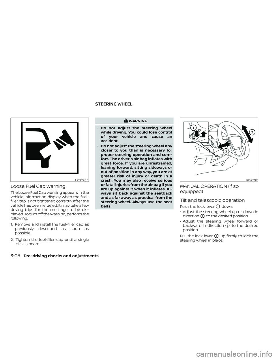
Push the lock leverO1down:
• Adjust the steering wheel up or down in direction
O2to the desired position.
• Adjust the steering wheel forward or backward in direction
O3to the desired
position.
Pull the lock lever
O1up firmly to lock the
steering wheel in place.
LPD2985LPD2597
STEERING WHEEL
3-26Pre-driving checks and adjustments
Page 227 of 635
AUTOMATIC OPERATION (if so
equipped)
Tilt and telescopic operation
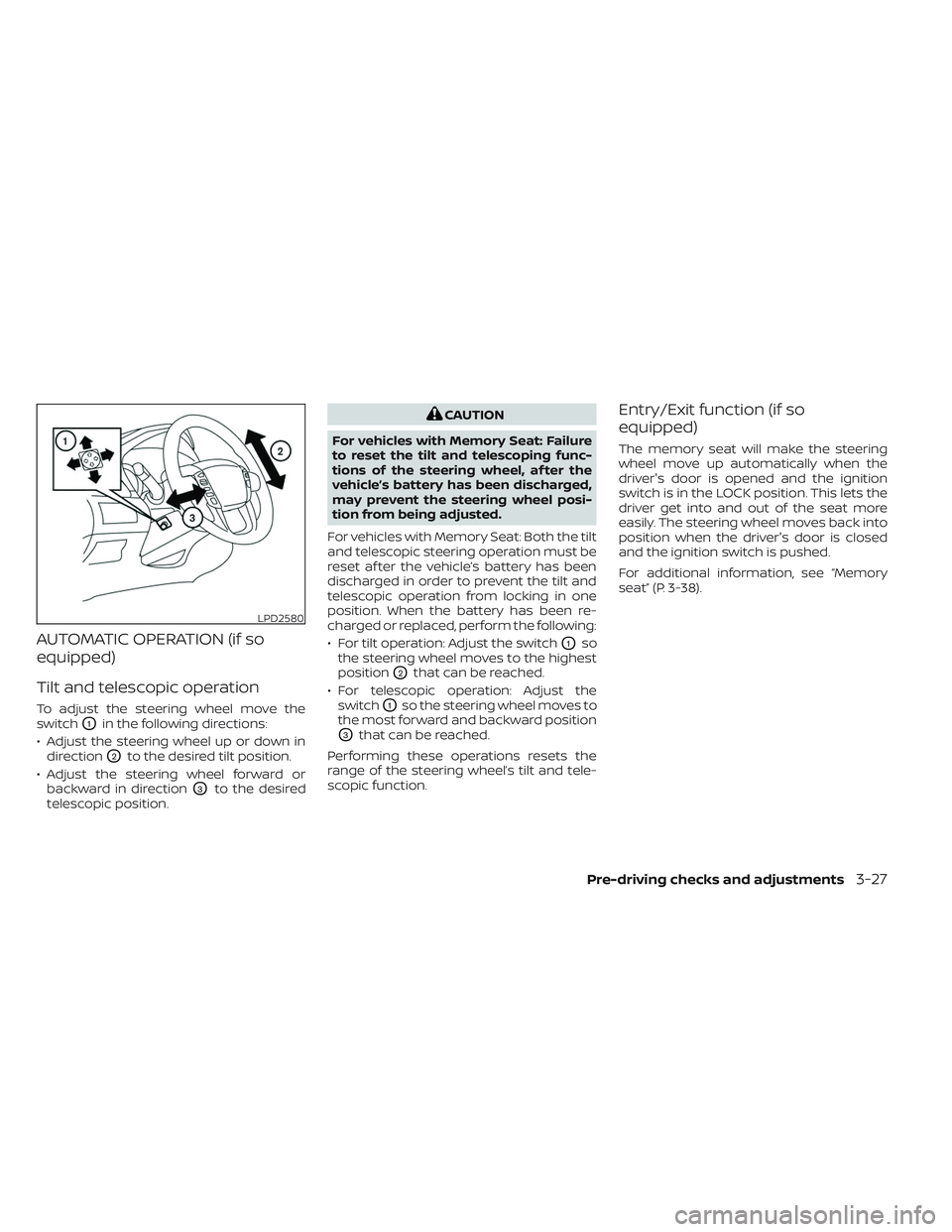
To adjust the steering wheel move the
switch
O1in the following directions:
• Adjust the steering wheel up or down in direction
O2to the desired tilt position.
• Adjust the steering wheel forward or backward in direction
O3to the desired
telescopic position.
CAUTION
For vehicles with Memory Seat: Failure
to reset the tilt and telescoping func-
tions of the steering wheel, af ter the
vehicle’s battery has been discharged,
may prevent the steering wheel posi-
tion from being adjusted.
For vehicles with Memory Seat: Both the tilt
and telescopic steering operation must be
reset af ter the vehicle’s battery has been
discharged in order to prevent the tilt and
telescopic operation from locking in one
position. When the battery has been re-
charged or replaced, perform the following:
• For tilt operation: Adjust the switch
O1so
the steering wheel moves to the highest
position
O2that can be reached.
• For telescopic operation: Adjust the switch
O1so the steering wheel moves to
the most forward and backward position
O3that can be reached.
Performing these operations resets the
range of the steering wheel’s tilt and tele-
scopic function.
Entry/Exit function (if so
equipped)
The memory seat will make the steering
wheel move up automatically when the
driver's door is opened and the ignition
switch is in the LOCK position. This lets the
driver get into and out of the seat more
easily. The steering wheel moves back into
position when the driver's door is closed
and the ignition switch is pushed.
For additional information, see “Memory
seat” (P. 3-38).
LPD2580
Pre-driving checks and adjustments3-27
Page 239 of 635
MEMORY STORAGE FUNCTION
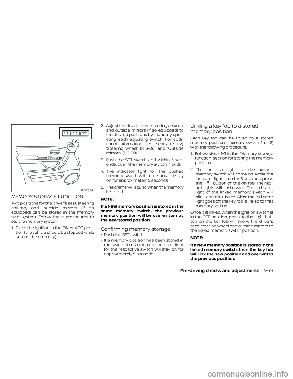
Two positions for the driver's seat, steering
column, and outside mirrors (if so
equipped) can be stored in the memory
seat system. Follow these procedures to
set the memory system.
1. Place the ignition in the ON or ACC posi-tion (the vehicle should be stopped while
setting the memory). 2. Adjust the driver's seat, steering column,
and outside mirrors (if so equipped) to
the desired positions by manually oper-
ating each adjusting switch. For addi-
tional information, see “Seats” (P. 1-2),
“Steering wheel” (P. 3-26) and “Outside
mirrors” (P. 3-30).
3. Push the SET switch and, within 5 sec- onds, push the memory switch (1 or 2).
4. The indicator light for the pushed memory switch will come on and stay
on for approximately 5 seconds.
5. The chime will sound when the memory is stored.NOTE:
If a NEW memory position is stored in the
same memory switch, the previous
memory position will be overwritten by
the new stored position.
Confirming memory storage
• Push the SET switch.
• If a memory position has been stored inthe switch (1 or 2) then the indicator light
for the respective switch will stay on for
approximately 5 seconds.
Linking a key fob to a stored
memory position
Each key fob can be linked to a stored
memory position (memory switch 1 or 2)
with the following procedure.
1. Follow steps 1-3 in the “Memory storage function” section for storing the memory
position.
2. The indicator light for the pushed memory switch will come on. While the
indicator light is on for 5 seconds, press
the
button on the key fob. The haz-
ard lights will flash twice. The indicator
light of the linked memory switch will
blink and click twice. Af ter the indicator
light goes off, the key fob is linked to that
memory setting.
Once it is linked, when the ignition switch is
in the OFF position, pressing the
but-
ton on the key fob will move the driver’s
seat, steering wheel and outside mirrors to
the linked memory switch position.
NOTE:
If a new memory position is stored in the
linked memory switch, then the key fob
will link the new position and overwrites
the previous position.
LPD2302
Pre-driving checks and adjustments3-39
Page 240 of 635
ENTRY/EXIT FUNCTION
This system is designed so that the driver's
seat and steering column will automati-
cally move when the shif t lever is in the P
(Park) position. This allows the driver to
easily get in and out of the driver’s seat.
The driver’s seat will slide backward and
the steering column will move up:
• When the driver’s door is opened with theignition switch in the OFF position.
• When the ignition switch is changed from ACC to OFF with the driver’s door open.
The driver’s seat and steering wheel will
return to the previous position:
• When the ignition switch is changed from ACC or ON while the shif t lever is in the P
(Park) position.
The entry/exit function can be adjusted or
canceled through the vehicle settings in
the vehicle information display by perform-
ing the following:
• Switch the Exit Seat Slide from ON to OFF.
• Switch the Exit Steering UP from ON to OFF.
Restarting the entry/exit function
If the battery cable is disconnected, or if the
fuse opens, the stored memory positions
will be lost and some of the functions will
be restricted:
1. Drive the vehicle over 25 mph (40 km/h).
OR
2. Open and close the driver's door more than two times with the ignition switch
in the OFF position.
The entry/exit function should now work
properly.
SYSTEM OPERATION
The memory seat system will not work or
will stop operating under the following
conditions:
• When the vehicle speed is above 4 mph (7 km/h).
• When any of the memory switches are pushed while the memory seat system is
operating.
• When the switch for the driver’s seat and steering column is pushed while the
memory seat system is operating.
• When the seat has already been moved to the memorized position. • When no seat position is stored in the
memory switch.
• When the shif t lever is moved from P (Park) to any other position.
The memory seat system can be adjusted
and canceled. It is recommended you visit
a NISSAN dealer for this service.
3-40Pre-driving checks and adjustments
Page 532 of 635
Brakes:Check that the brakes do not pull
the vehicle to one side when applied.
Parking brake: Check the parking brake
operation regularly. The vehicle should be
securely held on a fairly steep hill with only
the parking brake applied. If the parking
brake needs adjustment, it is recom-
mended that you visit a NISSAN dealer for
this service.
Seats: Check seat position controls such
as seat adjusters, seatback recliner, etc., to
ensure they operate smoothly and all
latches lock securely in every position.
Check that the head restraints/headrests
move up and down smoothly and the locks
(if so equipped) hold securely in all latched
positions.
Seat belts: Check that all parts of the seat
belt system (for example, buckles, anchors,
adjusters and retractors) operate properly
and smoothly, and are installed securely.
Check the belt webbing for cuts, fraying,
wear or damage.
Steering wheel: Check for changes in the
steering system, such as excessive free-
play, hard steering or strange noises.
Warning lights and chimes: Make sure all
warning lights and chimes are operating
properly. Windshield wiper and washer*:
Check
that the wipers and washer operate prop-
erly and that the wipers do not streak.
Windshield defroster: Check that the air
comes out of the defroster outlets properly
and in sufficient quantity when operating
the heater or air conditioner.
Under the hood and vehicle
The maintenance items listed here should
be checked periodically (for example, each
time you check the engine oil or refuel).
Battery* (for maintenance free batter-
ies): For vehicles equipped with a sealed
maintenance free battery. It is recom-
mended that you visit a NISSAN dealer for
service.
Battery* (for serviceable batteries):
Check the fluid level in each cell. The fluid
should be at the bottom of the filler open-
ing. Vehicles operated in high tempera-
tures or under severe conditions require
frequent checks of the battery fluid level.
NOTE:
Care should be taken to avoid situations
that can lead to potential battery dis-
charge and potential no-start conditions
such as:
1. Installation or extended use of elec- tronic accessories that consume bat-
tery power when the engine is not
running (Phone chargers, GPS, DVD
players, etc.).
2. Vehicle is not driven regularly and/or only driven short distances.
In these cases, the battery may need to
be charged to maintain battery health.
Brake fluid level*: Make sure that the brake
fluid level is between the MIN and MAX lines
on the reservoir.
Engine coolant level*: Check the coolant
level when the engine is cold.
Engine drive belts*: Make sure the drive
belts are not frayed, worn, cracked or oily.
Engine oil level*: Check the level af ter
parking the vehicle on a level surface with
the engine off. Wait more than 10 minutes
for the oil to drain back into the oil pan.
9-4Maintenance and schedules
Page 625 of 635

Power steering fluid............8-13Windshield-washer fluid.........8-15Fog light switch................2-52Forward Driving AidsSystem Temporarily
Unavailable
.......2-37, 5-67, 5-87, 5-99Front air bag system (See supplemental
restraint system)............1-60, 1-76Front and rear sonar system.......5-124Front power seat adjustment........1-6Front seats....................1-2Front-door pocket..............2-70FuelCapacities and recommended
fuel/lubricants
...............10-2Fuel economy...............5-107Fuel gauge................. .2-9Fuel octane rating.............10-6Fuel recommendation..........10-4Loose fuel cap warning..........2-33Fuel Cell Vehicle (FCV) System
Tire pressure................8-33Fuel efficient driving tips..........5-106Fuel gauge................... .2-9Fuel-filler door.................3-23Fuses......................8-24Fusible links..................8-25
G
Garage door opener, HomeLink® Universal
Transceiver........2-90, 2-91, 2-93, 2-94
Gauge
Automatic transmission fluid
temperature gauge
............2-10Engine coolant temperature gauge. . .2-8Engine oil pressure gauge........2-10Fuel gauge................. .2-9Odometer...................2-7Speedometer.................2-7Tachometer.................2-8Trip odometer................2-7Voltmeter..................2-10General maintenance.............9-2Glove box....................2-73Grocery hooks.................2-80
H
Hazard warning flasher switch........6-2Head restraints.................1-11Headlight aiming control..........2-50Headlight and turn signal switch.....2-45Headlight control switch..........2-45Headlights...................8-29Headlights, aiming control.........2-50Heated rear seats...............2-55Heated seats................. .2-54Heated steering wheel switch.......2-57Heater
Heater and air conditioner (automatic)
(if so equipped)
...............4-37Heater and air conditioner controls. .4-38Heater operation..........4-30, 4-39Heater and air conditioner (automatic). .4-37
Hill descent control switch.........2-59Hill descent control system........5-122Hill start assist system...........5-123HomeLink® Universal
Transceiver........2-90, 2-91, 2-93, 2-94Hood.......................3-23HookLuggage hook...............2-81Horn...................... .2-52
I
Ignition switch
Push-button ignition switch.......5-13Immobilizer system..........2-40, 5-16In-cabin microfilter..............8-21Increasing fuel economy..........5-107Inside automatic anti-glare mirror. . . .3-29Instrument brightness control.......2-51Instrument panel.............0-6, 2-4Instrument panel dimmer switch.....2-51Intelligent Around View Monitor.......4-11Intelligent Cruise Control...........5-51Intelligent Driver Alertness (I-DA).....5-102Intelligent Forward Collision Warning
(I-FCW)..................... .5-90Intelligent Key system
Key operating range............3-10Key operation................3-11Mechanical key................3-3Remote keyless entry operation. . . .3-15Troubleshooting guide..........3-19Warning signals...............3-19
11-3
Page 628 of 635
Child seat
belts........1-28,1-34, 1-40, 1-44, 1-49Reporting safety defects
(US only)................. .10-57Seat
Memory seat............3-38, 3-40Seat adjustmentFront manual seat adjustment......1-4Front power seat adjustment.......1-6Seat beltChild safety.................1-25Infants and small children........1-26Injured person................1-19Larger children...............1-26Precautions on seat belt usage.....1-16Pregnant women..............1-19Rear center seat belt...........1-23Seat belt extenders............1-24Seat belt maintenance..........1-24Seat belts................1-16,7-7Shoulder belt height adjustment. . . .1-24Three-point type with retractor.....1-19Seat belt extenders..............1-24Seat belt warning light............2-16Seatback pockets...............2-71SeatsAdjustment..................1-2Front seats..................1-2Heated seats................2-54Manual front seat adjustment......1-4Rear seat.................. .1-4Security indicator light............2-16Security system (NISSAN Vehicle Immobilizer
System), engine start.........2-40, 5-16
Security systems
Vehicle security system.........2-39Self-adjusting brakes.............8-23Service manual order form........10-59Servicing air conditioner...........4-42Shif tingAutomatic transmission.........5-20Shoulder belt height adjustment......1-24Side air bag system (See supplemental side
air bag, curtain and rollover air bag
systems)
.....................1-79Snow plow................. .10-55Spark plug replacement...........8-20Spark plugs...................8-20Specifications.................10-9Speedometer..................2-7Speedometer and odometer........2-6SRS warning label...............1-83Stability control................5-120Standard maintenance............9-8Starting
Before starting the engine........5-16Jump starting............6-10,8-19Precautions when starting
and driving...............5-4, 5-11Push starting................6-12Starting the engine............5-17Starting the engine..............5-17SteeringPower steering fluid............8-13Power steering system.........5-116Steering wheel.................3-26Stop light................... .8-30Storage.....................2-70
Storage tray..................2-74Sun visors....................3-28Sunglasses case................2-76Sunglasses holder..............2-76Sunroof..................2-86, 7-5Supplemental air bag warning
labels...................... .1-83Supplemental air bag warning
light....................1-83, 2-16Supplemental front impact air bag
system..................1-60, 1-76Supplemental restraint system
Information and warning labels.....1-83Precautions on supplemental
restraint system...........1-53, 1-68Supplemental restraint system
(Supplemental air bag system).......1-53SwitchAutolight switch..............2-45Automatic power window switch. . .2-84Electronic locking rear differential
(E-Lock) system switch..........2-60Fog light switch..............2-52Hazard warning flasher switch......6-2Headlight aiming control.........2-50Headlight and turn signal switch. . . .2-45Headlight control switch.........2-45Hill descent control switch........2-59Instrument brightness control.....2-51Power door lock switch..........3-6Power inverter switch...........2-61Rear sonar system OFF switch.....2-62Tow mode switch.............2-63Turn signal switch.............2-51
11-6