tow NISSAN TITAN 2022 Owners Manual
[x] Cancel search | Manufacturer: NISSAN, Model Year: 2022, Model line: TITAN, Model: NISSAN TITAN 2022Pages: 635, PDF Size: 7.78 MB
Page 12 of 635

1. Cargo lamp (P. 2-53)
2. Rear sliding window (P. 2-85)3. Bed liner storage bins (if so equipped)
(P. 2-80)
4. Under rail bed lamps (if so equipped)
(P. 8-30) 5. Truck box (P. 3-34)
Tailgate (P. 3-34)
Rearview camera (P. 4-10)
6. Towing (P. 10-32)
7. Rear sonar sensors (P. 5-124)
8. Replacing bulbs (P. 8-29)
9. Fuel-filler cap (P. 3-23) Fuel-filler door (P. 3-23)
Fuel recommendation (P. 10-4)
10. Child safety rear door lock
(if so equipped) (P. 3-4)
Refer to the page number indicated in
parentheses for operating details.
NOTE:
Crew Cab model shown, King Cab® model
similar.
LII2733
EXTERIOR REAR
0-4Illustrated table of contents
Page 14 of 635
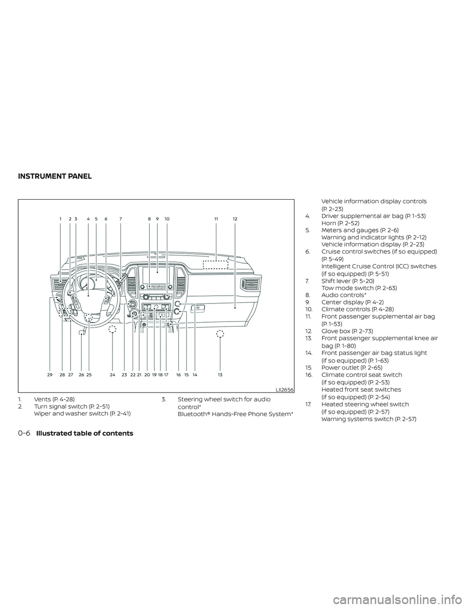
1. Vents (P. 4-28)
2. Turn signal switch (P. 2-51)Wiper and washer switch (P. 2-41) 3. Steering wheel switch for audio
control*
Bluetooth® Hands-Free Phone System* Vehicle information display controls
(P. 2-23)
4. Driver supplemental air bag (P. 1-53) Horn (P. 2-52)
5. Meters and gauges (P. 2-6) Warning and indicator lights (P. 2-12)
Vehicle information display (P. 2-23)
6. Cruise control switches (if so equipped)
(P. 5-49)
Intelligent Cruise Control (ICC) switches
(if so equipped) (P. 5-51)
7. Shif t lever (P. 5-20) Tow mode switch (P. 2-63)
8. Audio controls*
9. Center display (P. 4-2)
10. Climate controls (P. 4-28)
11. Front passenger supplemental air bag
(P. 1-53)
12. Glove box (P. 2-73)
13. Front passenger supplemental knee air
bag (P. 1-80)
14. Front passenger air bag status light
(if so equipped) (P. 1-63)
15. Power outlet (P. 2-65)
16. Climate control seat switch
(if so equipped) (P. 2-53)
Heated front seat switches
(if so equipped) (P. 2-54)
17. Heated steering wheel switch
(if so equipped) (P. 2-57)
Warning systems switch (P. 2-57)
LII2656
INSTRUMENT PANEL
0-6Illustrated table of contents
Page 19 of 635
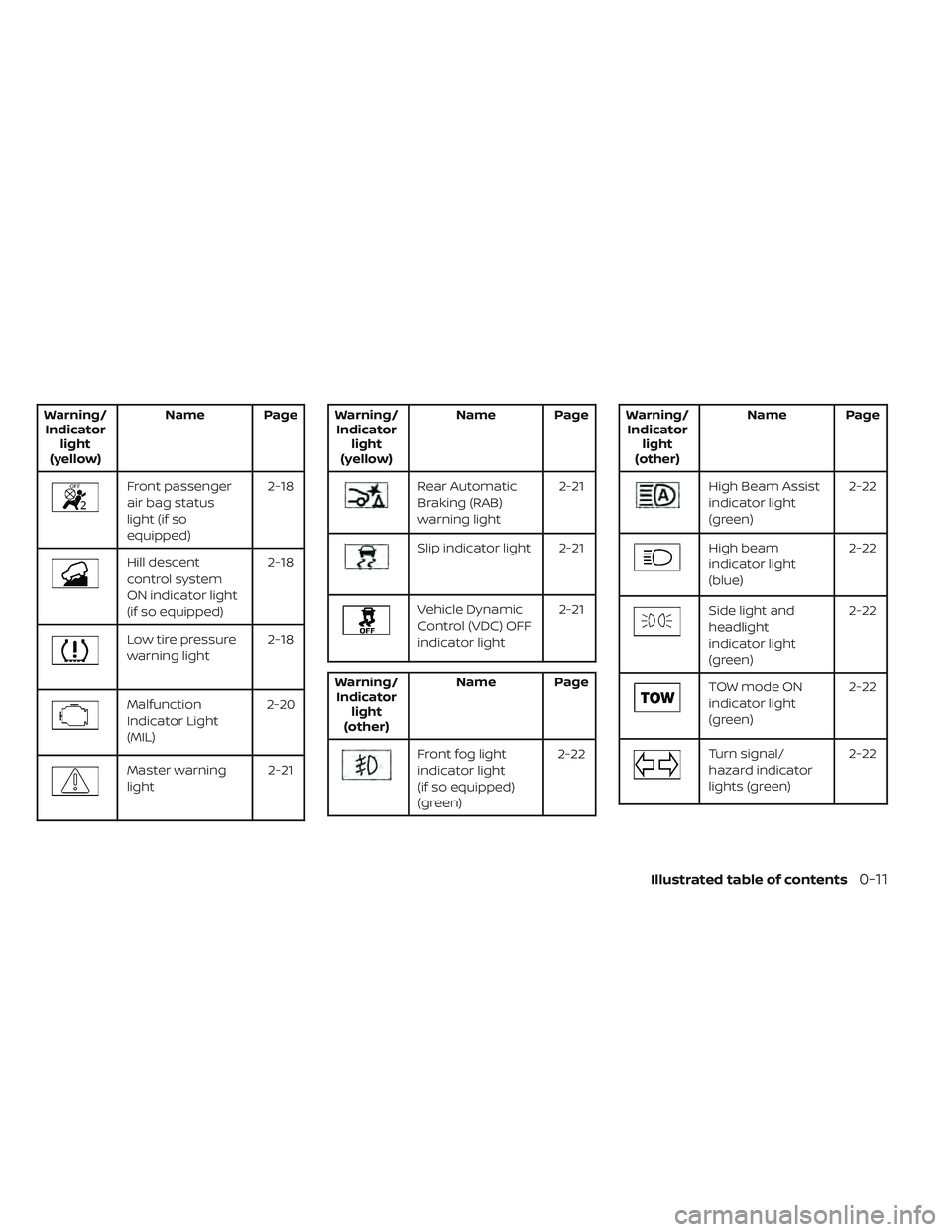
Warning/Indicator light
(yellow) Name Page
Front passenger
air bag status
light (if so
equipped) 2-18
Hill descent
control system
ON indicator light
(if so equipped)2-18
Low tire pressure
warning light
2-18
Malfunction
Indicator Light
(MIL)2-20
Master warning
light
2-21
Warning/
Indicator light
(yellow) Name Page
Rear Automatic
Braking (RAB)
warning light
2-21
Slip indicator light 2-21
Vehicle Dynamic
Control (VDC) OFF
indicator light2-21
Warning/
Indicator light
(other) Name Page
Front fog light
indicator light
(if so equipped)
(green) 2-22
Warning/
Indicator light
(other) Name Page
High Beam Assist
indicator light
(green)
2-22
High beam
indicator light
(blue)2-22
Side light and
headlight
indicator light
(green)2-22
TOW mode ON
indicator light
(green)
2-22
Turn signal/
hazard indicator
lights (green)2-22
Illustrated table of contents0-11
Page 42 of 635
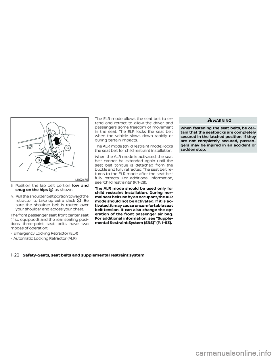
3. Position the lap belt portionlow and
snug on the hips
OBas shown.
4. Pull the shoulder belt portion toward the retractor to take up extra slack
OC.Be
sure the shoulder belt is routed over
your shoulder and across your chest.
The front passenger seat, front center seat
(if so equipped), and the rear seating posi-
tions three-point seat belts have two
modes of operation:
• Emergency Locking Retractor (ELR)
• Automatic Locking Retractor (ALR) The ELR mode allows the seat belt to ex-
tend and retract to allow the driver and
passengers some freedom of movement
in the seat. The ELR locks the seat belt
when the vehicle slows down rapidly or
during certain impacts.
The ALR mode (child restraint mode) locks
the seat belt for child restraint installation.
When the ALR mode is activated, the seat
belt cannot be extended again until the
seat belt tongue is detached from the
buckle and fully retracted. The seat belt re-
turns to the ELR mode af ter the seat belt
fully retracts. For additional information,
see “Child restraints” (P. 1-28).
The ALR mode should be used only for
child restraint installation. During nor-
mal seat belt use by an occupant, the ALR
mode should not be activated. If it is ac-
tivated, it may cause uncomfortable seat
belt tension. It can also change the op-
eration of the front passenger air bag.
For additional information, see “Supple-
mental Restraint System (SRS)” (P. 1-53).
WARNING
When fastening the seat belts, be cer-
tain that the seatbacks are completely
secured in the latched position. If they
are not completely secured, passen-
gers may be injured in an accident or
sudden stop.
LRS2675
1-22Safety-Seats, seat belts and supplemental restraint system
Page 72 of 635
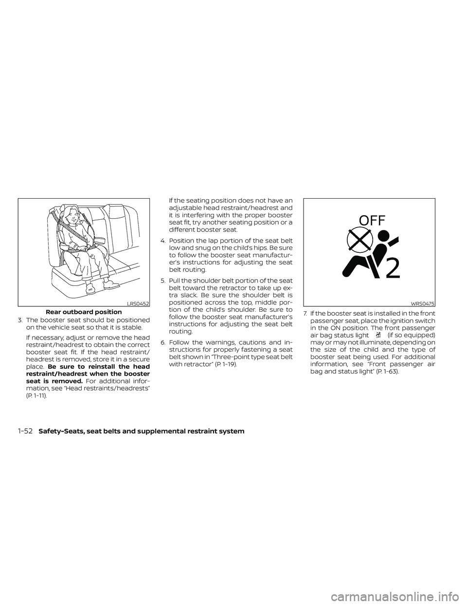
3. The booster seat should be positionedon the vehicle seat so that it is stable.
If necessary, adjust or remove the head
restraint/headrest to obtain the correct
booster seat fit. If the head restraint/
headrest is removed, store it in a secure
place. Be sure to reinstall the head
restraint/headrest when the booster
seat is removed. For additional infor-
mation, see “Head restraints/headrests”
(P. 1-11). If the seating position does not have an
adjustable head restraint/headrest and
it is interfering with the proper booster
seat fit, try another seating position or a
different booster seat.
4. Position the lap portion of the seat belt low and snug on the child’s hips. Be sure
to follow the booster seat manufactur-
er’s instructions for adjusting the seat
belt routing.
5. Pull the shoulder belt portion of the seat belt toward the retractor to take up ex-
tra slack. Be sure the shoulder belt is
positioned across the top, middle por-
tion of the child’s shoulder. Be sure to
follow the booster seat manufacturer’s
instructions for adjusting the seat belt
routing.
6. Follow the warnings, cautions and in- structions for properly fastening a seat
belt shown in “Three-point type seat belt
with retractor” (P. 1-19). 7. If the booster seat is installed in the front
passenger seat, place the ignition switch
in the ON position. The front passenger
air bag status light
(if so equipped)
may or may not illuminate, depending on
the size of the child and the type of
booster seat being used. For additional
information, see “Front passenger air
bag and status light” (P. 1-63).
LRS0452
Rear outboard position
WRS0475
1-52Safety-Seats, seat belts and supplemental restraint system
Page 87 of 635
NOTE:
A system check will be performed during
which the front passenger air bag status
light will remain lit for about 7 seconds
initially.
If the light is still ON af ter this, the person
should be advised not to ride in the front
passenger seat and the vehicle should be
checked as soon as possible. It is recom-
mended that you visit a NISSAN dealer for
this service.
Other supplemental front-impact air
bag precautions
WARNING
• Do not place any objects on the
steering wheel pad or on the instru-
ment panel. Also, do not place any
objects between any occupant and
the steering wheel or instrument
panel. Such objects may become
dangerous projectiles and cause in-
jury if the front air bags inflate.
• Immediately af ter inflation, several
front air bag system components will
be hot. Do not touch them; you may
severely burn yourself. •
No unauthorized changes should be
made to any components or wiring
of the supplemental air bag system.
This is to prevent accidental inflation
of the supplemental air bag or dam-
age to the supplemental air bag
system.
• Do not make unauthorized changes
to your vehicle's electrical system,
suspension system or front end
structure. This could affect proper
operation of the front air bag system.
• Tampering with the front air bag sys-
tem may result in serious personal
injury. Tampering includes changes
to the steering wheel and the instru-
ment panel assembly by placing ma-
terial over the steering wheel pad
and above the instrument panel or
by installing additional trim material
around the air bag system.
• Removing or modif ying the front
passenger seat may affect the func-
tion of the air bag system and result
in serious personal injury. •
Modif ying or tampering with the
front passenger seat may result in
serious personal injury. For example,
do not change the front seats by
placing material on the seat cushion
or by installing additional trim mate-
rial, such as seat covers, on the seat
that are not specifically designed to
assure proper air bag operation. Ad-
ditionally, do not stow any objects
under the front passenger seat or the
seat cushion and seatback. Such ob-
jects may interfere with the proper
operation of the occupant classifica-
tion sensor (weight sensor).
• No unauthorized changes should be
made to any components or wiring
of the seat belt system. This may af-
fect the front air bag system. Tam-
pering with the seat belt system may
result in serious personal injury.
Safety-Seats, seat belts and supplemental restraint system1-67
Page 108 of 635
Hill descent control switch (if so equipped).....2-59
Electronic locking rear differential (E-Lock)
system switch (if so equipped) .................2-60
Power inverter switch (if so equipped) ..........2-61
Parking Aids system switch ....................2-62
Tow mode switch .............................. 2-63
Emergency call (SOS) button (if so equipped) . . . 2-63
Trailer Brake Controller Unit (TBCU)
(if so equipped) ................................. 2-63
Rear Door Alert ................................. 2-64
Power outlets .................................. 2-65
12v Outlets .................................. 2-65
120v outlets (if so equipped) .................2-66
USB/iPod® charging ports (if so equipped) ......2-68
Extended storage switch .......................2-69
Storage ........................................ 2-70
Front-door pockets ......................... 2-70
Rear-door pockets .......................... 2-70
Console side pockets (if so equipped) .......2-70
Seatback pockets ........................... 2-71
Under-seat storage (if so equipped) .........2-71
Console box storage trays
(if so equipped) .............................. 2-73
Cell phone storage tray (if so equipped) .....2-73
Glovebox ................................... 2-73Console box (if so equipped)
................2-74
Center armrest storage (if so equipped) .....2-75
Under front seat storage bin
(if so equipped) .............................. 2-76
Overhead sunglasses storage
(if so equipped) .............................. 2-76
Cup holders ................................. 2-77
Grocery hooks (if so equipped) ..............2-80
Bed liner storage bins (if so equipped) .......2-80
Cargo hooks (if so equipped) ................2-81
C-Channel cargo hooks (if so equipped) .....2-81
Windows ....................................... 2-82
Power windows ............................. 2-82
Rear power window switch
(if so equipped) .............................. 2-84
Rear sliding window (if so equipped) .........2-85
Moonroof (if so equipped) ......................2-86
P
ower moonroof ............................ 2-86
Interior lights ................................... 2-88
Console light (if so equipped) ................2-89
Map lights (if so equipped) ...................2-89
Personal Lights (if so equipped) .............2-90
HomeLink® Universal Transceiver
(if so equipped) ................................. 2-90
Programming HomeLink® ...................2-91
Page 110 of 635
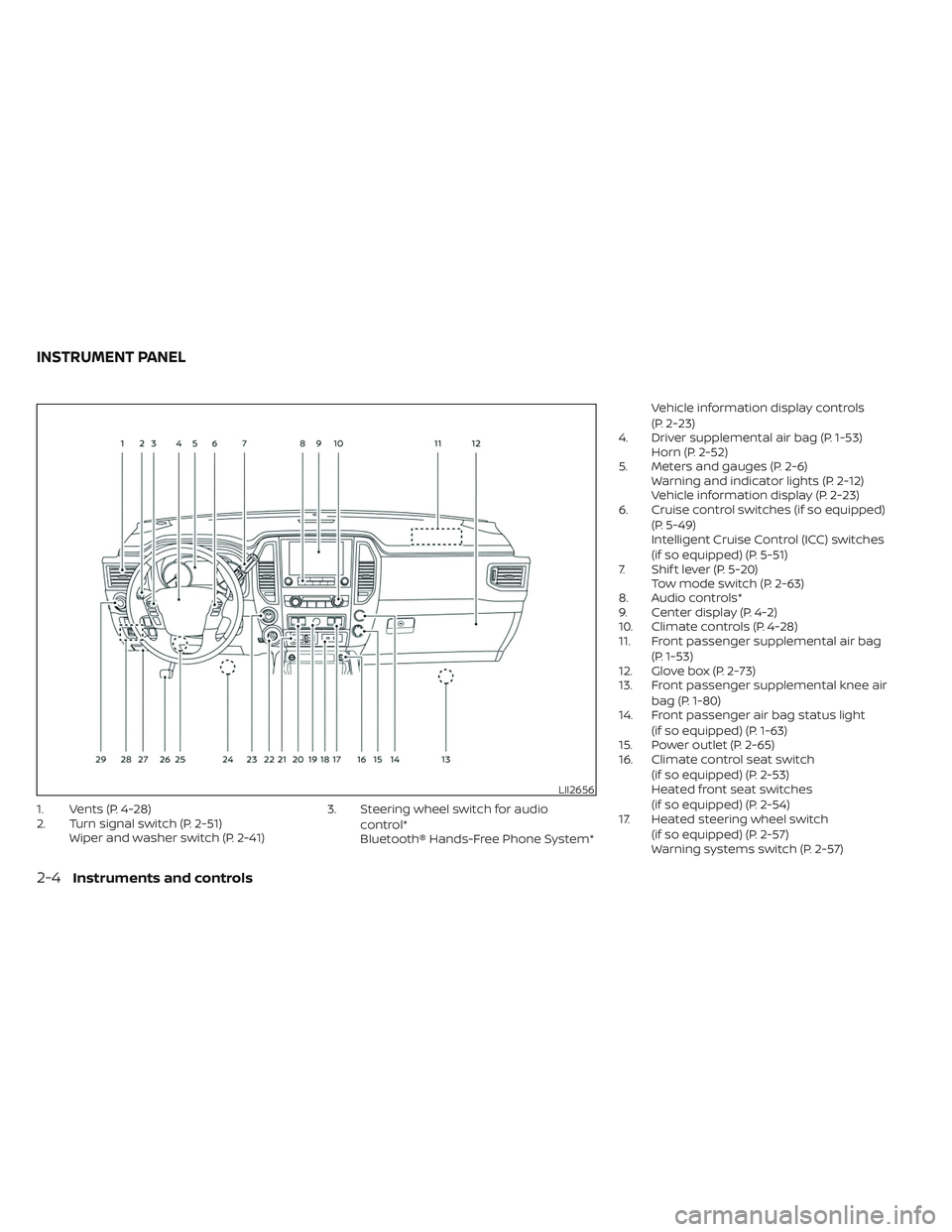
1. Vents (P. 4-28)
2. Turn signal switch (P. 2-51)Wiper and washer switch (P. 2-41) 3. Steering wheel switch for audio
control*
Bluetooth® Hands-Free Phone System* Vehicle information display controls
(P. 2-23)
4. Driver supplemental air bag (P. 1-53) Horn (P. 2-52)
5. Meters and gauges (P. 2-6) Warning and indicator lights (P. 2-12)
Vehicle information display (P. 2-23)
6. Cruise control switches (if so equipped)
(P. 5-49)
Intelligent Cruise Control (ICC) switches
(if so equipped) (P. 5-51)
7. Shif t lever (P. 5-20) Tow mode switch (P. 2-63)
8. Audio controls*
9. Center display (P. 4-2)
10. Climate controls (P. 4-28)
11. Front passenger supplemental air bag
(P. 1-53)
12. Glove box (P. 2-73)
13. Front passenger supplemental knee air
bag (P. 1-80)
14. Front passenger air bag status light
(if so equipped) (P. 1-63)
15. Power outlet (P. 2-65)
16. Climate control seat switch
(if so equipped) (P. 2-53)
Heated front seat switches
(if so equipped) (P. 2-54)
17. Heated steering wheel switch
(if so equipped) (P. 2-57)
Warning systems switch (P. 2-57)
LII2656
INSTRUMENT PANEL
2-4Instruments and controls
Page 118 of 635
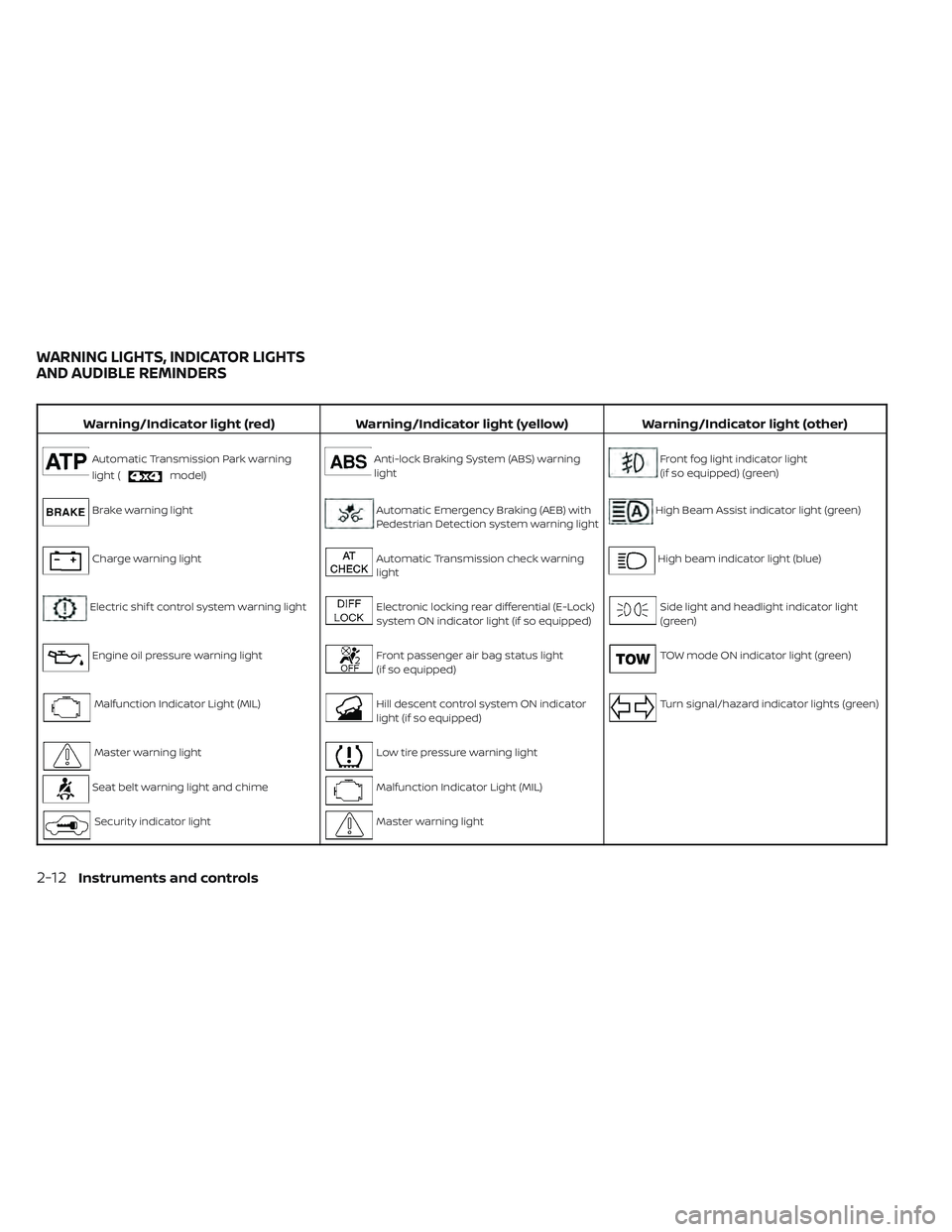
Warning/Indicator light (red)Warning/Indicator light (yellow) Warning/Indicator light (other)
Automatic Transmission Park warning
light (
model)
Anti-lock Braking System (ABS) warning
lightFront fog light indicator light
(if so equipped) (green)
Brake warning lightAutomatic Emergency Braking (AEB) with
Pedestrian Detection system warning lightHigh Beam Assist indicator light (green)
Charge warning lightAutomatic Transmission check warning
lightHigh beam indicator light (blue)
Electric shif t control system warning lightElectronic locking rear differential (E-Lock)
system ON indicator light (if so equipped)Side light and headlight indicator light
(green)
Engine oil pressure warning lightFront passenger air bag status light
(if so equipped)TOW mode ON indicator light (green)
Malfunction Indicator Light (MIL)Hill descent control system ON indicator
light (if so equipped)Turn signal/hazard indicator lights (green)
Master warning lightLow tire pressure warning light
Seat belt warning light and chimeMalfunction Indicator Light (MIL)
Security indicator lightMaster warning light
WARNING LIGHTS, INDICATOR LIGHTS
AND AUDIBLE REMINDERS
2-12Instruments and controls
Page 120 of 635
•If the ATP light is on, this indicates
that the automatic transmission P
(Park) position will not function and
the transfer case is in neutral.
• When parking, always make sure that
the 4WD shif t indicator light illumi-
nates and the parking brake is set.
Failure to engage the transfer posi-
tion in 2WD, 4H or 4LO could result in
the vehicle moving unexpectedly, re-
sulting in serious personal injury or
property damage.
• Shif t the 4WD switch into the 2WD, 4H
or 4LO position again to turn off the
ATP warning light when the shif t le-
ver is in the P position and the ATP
warning light is on. (Before shif ting
the 4WD switch into the 4LO position,
move the shif t lever to the N position
once, shif t the shif t lever into P again
and make sure the ATP warning light
is off.)
This light indicates that the automatic
transmission parking function is not en-
gaged. If the transfer control is not secured
in any drive position while the shif t lever is
in the P (Park) position, the transmission will
disengage and the drive wheels will not
lock.Brake warning light
This light functions for both the parking
brake and the foot brake systems.
Parking brake indicator
When the ignition switch is placed in the ON
position, the light comes on when the park-
ing brake is applied.
Low brake fluid warning light
When the ignition switch is placed in the ON
position, the light warns of a low brake fluid
level. If the light comes on while the engine
is running, with the parking brake not ap-
plied, stop the vehicle and perform the
following:
1. Check the brake fluid level. Add brake fluid as necessary. For additional infor-
mation, see “Brake fluid” (P. 8-14).
2. If the brake fluid level is correct, have the warning system checked. It is recom-
mended that you visit a NISSAN dealer
for this service.
WARNING
• Your brake system may not be work-
ing properly if the warning light is on.
Driving could be dangerous. If you
judge it to be safe, drive carefully to
the nearest service station for re-
pairs. Otherwise, have your vehicle
towed because driving it could be
dangerous.
• Pressing the brake pedal with the en-
gine stopped and/or a low brake
fluid level may increase your stop-
ping distance and braking will re-
quire greater pedal effort and pedal
travel.
• If the brake fluid level is below the
MINIMUM or MIN mark on the brake
fluid reservoir, do not drive until the
brake system has been checked. It is
recommended that you visit a
NISSAN dealer for this service.
2-14Instruments and controls