Running lights NISSAN TITAN 2023 Owners Manual
[x] Cancel search | Manufacturer: NISSAN, Model Year: 2023, Model line: TITAN, Model: NISSAN TITAN 2023Pages: 644, PDF Size: 7.8 MB
Page 11 of 644
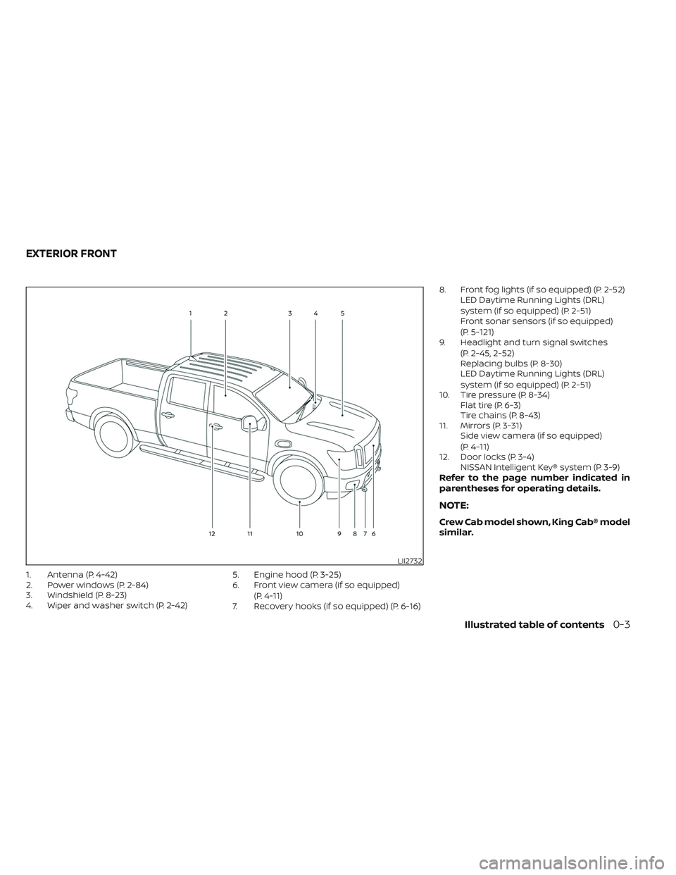
1. Antenna (P. 4-42)
2. Power windows (P. 2-84)
3. Windshield (P. 8-23)
4. Wiper and washer switch (P. 2-42)5. Engine hood (P. 3-25)
6. Front view camera (if so equipped)
(P. 4-11)
7. Recovery hooks (if so equipped) (P. 6-16) 8. Front fog lights (if so equipped) (P. 2-52)
LED Daytime Running Lights (DRL)
system (if so equipped) (P. 2-51)
Front sonar sensors (if so equipped)
(P. 5-121)
9. Headlight and turn signal switches
(P. 2-45, 2-52)
Replacing bulbs (P. 8-30)
LED Daytime Running Lights (DRL)
system (if so equipped) (P. 2-51)
10. Tire pressure (P. 8-34) Flat tire (P. 6-3)
Tire chains (P. 8-43)
11. Mirrors (P. 3-31) Side view camera (if so equipped)
(P. 4-11)
12. Door locks (P. 3-4) NISSAN Intelligent Key® system (P. 3-9)
Refer to the page number indicated in
parentheses for operating details.
NOTE:
Crew Cab model shown, King Cab® model
similar.
LII2732
EXTERIOR FRONT
Illustrated table of contents0-3
Page 105 of 644

2 Instruments and controls
Instrument panel................................2-4
Meters and gauges .............................2-6
Speedometer and odometer .................2-6
Tachometer ..................................2-8
Engine coolant temperature gauge ..........2-8
Fuel gauge ...................................2-9
Distance To Empty (DTE) .....................2-9
Auxiliary gauges (if so equipped) ............2-10
Off-road and 4–Wheel Drive (4WD)
monitor (if so equipped) ......................2-11
Eco Drive Report (if so equipped) ............2-12
Warning lights, indicator lights and audible
reminders ...................................... 2-13
Checking lights .............................. 2-15
Warning/Indicator lights (red) ...............2-15
Warning/Indicator lights (yellow) ............2-19
Warning/Indicator lights (other) .............2-23
Audible reminders ........................... 2-24
Vehicle information display .....................2-24
How to use the vehicle information
display ...................................... 2-25
Startup display .............................. 2-25
Settings ..................................... 2-25
Vehicle information display warnings
and indicators ............................... 2-33
Security systems ............................... 2-40Vehicle security system
.....................2-40
NISSAN Vehicle Immobilizer System .........2-41
Wiper and washer switch .......................2-42
Switch operation ............................ 2-42
Rain-sensing auto wiper system
(if so equipped) .............................. 2-44
Rear window and/or outside mirror defroster
switch (if so equipped) ......................... 2-45
Headlight switch ............................... 2-45
Headlight control switch ....................2-45
LED Daytime Running Lights (DRL)
system (if so equipped) ......................2-51
Instrument brightness control ..............2-51
Turn signal switch ........................... 2-52
Fog light switch (if so equipped) ................2-52
Horn ........................................... 2-53
Cargo lamp switch ............................. 2-53
Climate
controlled seat switches
(if so equipped) ................................. 2-54
Heated seat switches (if so equipped) ..........2-55
Heated rear seat switches (if so equipped) .....2-56
Heated steering wheel switch (if so equipped) . . 2-57
Warning systems switch .......................2-58
Vehicle Dynamic Control (VDC) OFF switch .....2-59
Hill descent control switch (if so equipped) .....2-59
Page 123 of 644
WARNING/INDICATOR LIGHTS
(yellow)
For additional information, see “Vehicle in-
formation display” (P. 2-24).
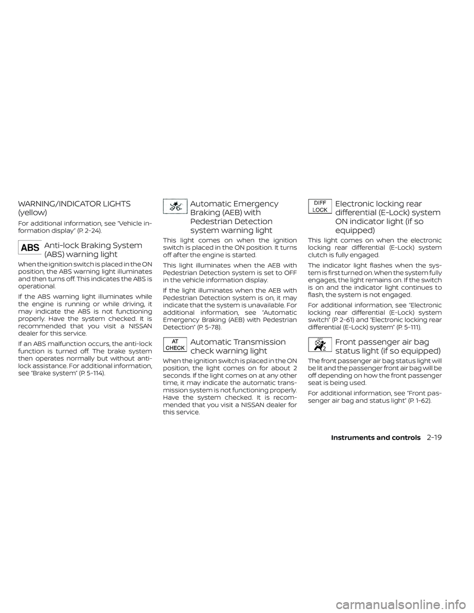
Anti-lock Braking System
(ABS) warning light
When the ignition switch is placed in the ON
position, the ABS warning light illuminates
and then turns off. This indicates the ABS is
operational.
If the ABS warning light illuminates while
the engine is running or while driving, it
may indicate the ABS is not functioning
properly. Have the system checked. It is
recommended that you visit a NISSAN
dealer for this service.
If an ABS malfunction occurs, the anti-lock
function is turned off. The brake system
then operates normally but without anti-
lock assistance. For additional information,
see “Brake system” (P. 5-114).
Automatic Emergency
Braking (AEB) with
Pedestrian Detection
system warning light
This light comes on when the ignition
switch is placed in the ON position. It turns
off af ter the engine is started.
This light illuminates when the AEB with
Pedestrian Detection system is set to OFF
in the vehicle information display.
If the light illuminates when the AEB with
Pedestrian Detection system is on, it may
indicate that the system is unavailable. For
additional information, see “Automatic
Emergency Braking (AEB) with Pedestrian
Detection” (P. 5-78).
Automatic Transmission
check warning light
When the ignition switch is placed in the ON
position, the light comes on for about 2
seconds. If the light comes on at any other
time, it may indicate the automatic trans-
mission system is not functioning properly.
Have the system checked. It is recom-
mended that you visit a NISSAN dealer for
this service.
Electronic locking rear
differential (E-Lock) system
ON indicator light (if so
equipped)
This light comes on when the electronic
locking rear differential (E-Lock) system
clutch is fully engaged.
The indicator light flashes when the sys-
tem is first turned on. When the system fully
engages, the light remains on. If the switch
is on and the indicator light continues to
flash, the system is not engaged.
For additional information, see “Electronic
locking rear differential (E-Lock) system
switch” (P. 2-61) and “Electronic locking rear
differential (E-Lock) system” (P. 5-111).
Front passenger air bag
status light (if so equipped)
The front passenger air bag status light will
be lit and the passenger front air bag will be
off depending on how the front passenger
seat is being used.
For additional information, see “Front pas-
senger air bag and status light” (P. 1-62).
Instruments and controls2-19
Page 140 of 644
NOTE:
Opening and closing a rear door while
stopped will reset this warning, similar to
pushing the ignition switch to ON again.
NOTE:
In vehicles with only 2 seats in the rear
row, only 2 seats will be displayed.
Release Parking Brake
This warning appears in the message area
of the vehicle information display when the
parking brake is set and the vehicle is
driven. Press the brake pedal to release the
parking brake.
Reminder: Turn OFF
Headlights
This warning appears when the headlights
are lef t in the ON position when exiting the
vehicle. Place the headlight switch in the
OFF or AUTO position. For additional infor-
mation, see “Headlight control switch”
(P. 2-45).
Remote Engine Start Mode
This warning appears in the vehicle infor-
mation display when the vehicle has been
started using the remote start function. Tostart the vehicle, apply the brake and place
the ignition switch in the ON position.
Shif t to Park
This warning appears when the ignition
switch is in the ACC or OFF position and the
shif t lever is not in the P (Park) position. Also,
a chime sounds when the ignition switch is
in the ACC or OFF position.
If this warning appears, move the shif t lever
to the P (Park) position and start the engine.
Shipping Mode On Push Storage Fuse
This warning may appear if the extended
storage switch is not pushed in. When this
warning appears, push in the extended
storage switch to turn off the warning. For
additional information, see “Extended stor-
age switch” (P. 2-71).
Tire Pressure Low - Add Air
This warning appears when the low tire
pressure warning light in the meter illumi-
nates and low tire pressure is detected. The
warning appears each time the ignition
switch is placed in the ON position as long
as the low tire pressure warning light re-
mains illuminated. If this warning appears,
stop the vehicle and adjust the tire pres-
sures of all four tires to the recommended
COLD tire pressure shown on the Tire and
Loading Information label. For additional
information, see “Low tire pressure warning
light” (P. 2-20) and “Tire Pressure Monitoring
System (TPMS)” (P. 5-5).
TPMS Error: See Owner’s Manual
This warning appears when there is an er-
ror with your TPMS. If this warning appears,
have the system checked. It is recom-
mended that you visit a NISSAN dealer for
this service.
When parked apply parking
brake
This message appears when a malfunc-
tion occurs in the electric shif t control sys-
tem below 3 mph (5 km/h).
Have the system checked. It is recom-
mended that you visit a NISSAN dealer for
this service.
4WD Error: See Owner’s
Manual
This warning appears when the 4-wheel
drive system is not functioning properly
while the engine is running.
2-36Instruments and controls
Page 154 of 644
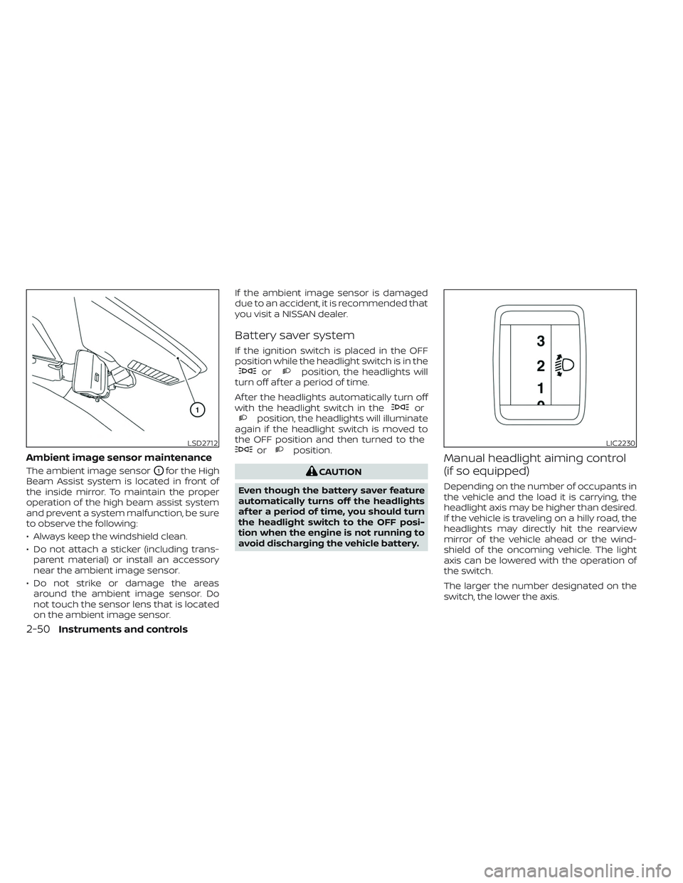
Ambient image sensor maintenance
The ambient image sensorO1for the High
Beam Assist system is located in front of
the inside mirror. To maintain the proper
operation of the high beam assist system
and prevent a system malfunction, be sure
to observe the following:
• Always keep the windshield clean.
• Do not attach a sticker (including trans- parent material) or install an accessory
near the ambient image sensor.
• Do not strike or damage the areas around the ambient image sensor. Do
not touch the sensor lens that is located
on the ambient image sensor. If the ambient image sensor is damaged
due to an accident, it is recommended that
you visit a NISSAN dealer.
Battery saver system
If the ignition switch is placed in the OFF
position while the headlight switch is in the
orposition, the headlights will
turn off af ter a period of time.
Af ter the headlights automatically turn off
with the headlight switch in the
orposition, the headlights will illuminate
again if the headlight switch is moved to
the OFF position and then turned to the
orposition.
CAUTION
Even though the battery saver feature
automatically turns off the headlights
af ter a period of time, you should turn
the headlight switch to the OFF posi-
tion when the engine is not running to
avoid discharging the vehicle battery.
Manual headlight aiming control
(if so equipped)
Depending on the number of occupants in
the vehicle and the load it is carrying, the
headlight axis may be higher than desired.
If the vehicle is traveling on a hilly road, the
headlights may directly hit the rearview
mirror of the vehicle ahead or the wind-
shield of the oncoming vehicle. The light
axis can be lowered with the operation of
the switch.
The larger the number designated on the
switch, the lower the axis.
LSD2712LIC2230
2-50Instruments and controls
Page 155 of 644
When traveling without a heavy load or on a
flat road, select position 0.
Select the switch position by referring to
the following sample.
Vehicle LoadSwitch
Position
Driver only or Driver/front passenger 0
Driver/front seat
passenger/rear seat pas- sengers 1
Driver/front seat
passenger/rear seat
passengers/cargo or
driver/cargo/no trailer 2
Fully loaded/no trailer 3
LED DAYTIME RUNNING LIGHTS
(DRL) SYSTEM (if so equipped)
The LED portion of the headlights auto-
matically illuminates at 100% intensity
when the engine is started and the parking
brake released. The LED Daytime Running
Lights (LED DRL) operate with the headlight
switch in the OFF or AUTO position. When
you turn the headlight switch to the
position for full illumination, the LED lights
switch from LED DRL to the park function.
If the parking brake is applied before the
engine is started, the LED DRL do not illumi-
nate. The LED DRL illuminate when the
parking brake is released. The LED DRL re-
main on while the engine is running.
It is necessary at dusk to turn the headlight
switch ON for interior controls and
switches to illuminate, as those remain off
while the switch is in the OFF position.
WARNING
When the LED DRL system is active, tail
lights on your vehicle are not on. It is
necessary at dusk to turn on your
headlights. Failure to do so could cause
an accident injuring yourself and
others.
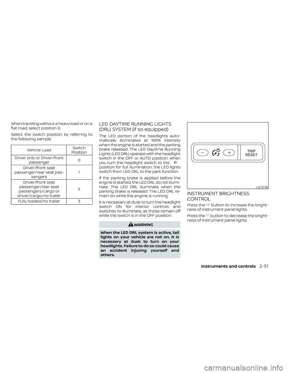
INSTRUMENT BRIGHTNESS
CONTROL
Press the “+” button to increase the bright-
ness of instrument panel lights.
Press the “-” button to decrease the bright-
ness of instrument panel lights.
LIC3176
Instruments and controls2-51
Page 171 of 644
12V OUTLETS
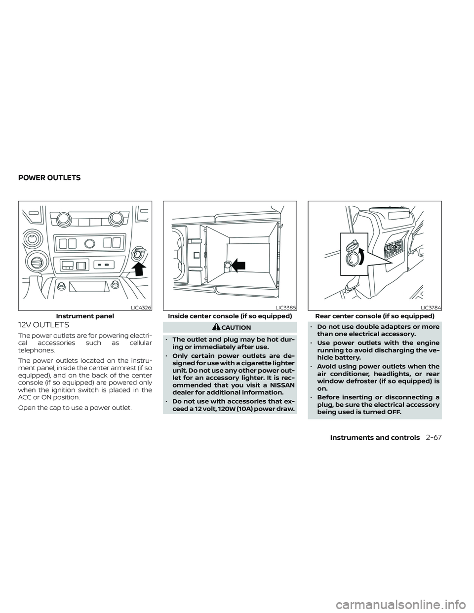
The power outlets are for powering electri-
cal accessories such as cellular
telephones.
The power outlets located on the instru-
ment panel, inside the center armrest (if so
equipped), and on the back of the center
console (if so equipped) are powered only
when the ignition switch is placed in the
ACC or ON position.
Open the cap to use a power outlet.
CAUTION
• The outlet and plug may be hot dur-
ing or immediately af ter use.
• Only certain power outlets are de-
signed for use with a cigarette lighter
unit. Do not use any other power out-
let for an accessory lighter. It is rec-
ommended that you visit a NISSAN
dealer for additional information.
• Do not use with accessories that ex-
ceed a 12 volt, 120W (10A) power draw. •
Do not use double adapters or more
than one electrical accessory.
• Use power outlets with the engine
running to avoid discharging the ve-
hicle battery.
• Avoid using power outlets when the
air conditioner, headlights, or rear
window defroster (if so equipped) is
on.
• Before inserting or disconnecting a
plug, be sure the electrical accessory
being used is turned OFF.
LIC4326
Instrument panel
LIC3385
Inside center console (if so equipped)
LIC3784
Rear center console (if so equipped)
POWER OUTLETS
Instruments and controls2-67
Page 174 of 644
Do not use the outlet located in the truck
box with accessories that exceed 120 volt.
Do not use double adapters or more than
one electrical accessory. When the dual
wall bed liner is installed (if so equipped),
the power outlet is still accessible through
the access door in the bed liner.
CAUTION
• Operation of the 120 volt system with
the ignition in the ON position and
the engine not running (idle) will
drain the battery charge. This could
lead to a dead battery or no start
condition.
• The outlet and plug may be hot dur-
ing or immediately af ter use.
• Use power outlets with the engine
running to avoid discharging the ve-
hicle battery.
• Do not use double adaptors or more
than one electrical accessory.
• Avoid using power outlets when the
air conditioner, headlights or rear
window defroster is on.
• Before inserting or disconnecting a
plug, be sure the electrical accessory
being used is turned OFF. •
Push the plug in as far as it will go. If
good contact is not made, the plug
may overheat or the internal tem-
perature fuse may open.
• When not in use, be sure to close the
cap. Do not allow water or any other
liquid to contact the outlet.
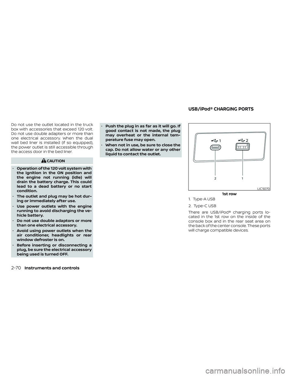
1. Type-A USB
2. Type-C USB
There are USB/iPod® charging ports lo-
cated in the 1st row on the inside of the
console box and in the rear seat area on
the back of the center console. These ports
will charge compatible devices.
LIC5070
1st row
USB/iPod® CHARGING PORTS
2-70Instruments and controls
Page 229 of 644
CAUTION
When the Intelligent Key battery is dis-
charged or other strong radio wave
sources are present near the operating
location, the Intelligent Key operating
range becomes narrower, and the Intel-
ligent Key may not function properly.
The Remote Engine Start function can only
be used when the Intelligent Key is within
the specified operating range from the
vehicle.
The Remote Engine Start operating range
is approximately 197 f t (60 m) from the
vehicle.
REMOTE STARTING THE VEHICLE
To use the Remote Engine Start feature to
start the engine perform the following:
1. Aim the Intelligent Key at the vehicle.
2. Press the
button to lock all doors.
3. Within 5 seconds press and hold the
button until the turn signal lights
flash and the tail lamps turn on. If the
vehicle is not within view press and hold
the
button for at least 2 seconds. The following events will occur when the
engine starts:
• The parking lights will turn on and remain
on as long as the engine is running.
• The doors will be locked and the climate control system may come on.
• The engine will continue to run for 10 min- utes. Repeat the steps to extend the time
for an additional 10 minutes. For addi-
tional information, see “Extending engine
run time” (P. 3-23).
Press and hold the brake then push the
push-button ignition switch to the ON po-
sition before driving. For additional infor-
mation, see “Driving the vehicle” (P. 5-18)).
EXTENDING ENGINE RUN TIME
The Remote Engine Start feature can be
extended one time by performing the
steps listed in “Remote starting the vehicle”
in this section. Run time will be calculated
as follows:
• The first 10 minute run time will start when the Remote Engine Start function is
performed. • The second 10 minutes will start immedi-
ately when the Remote Engine Start
function is performed again. For example,
if the engine has been running for 5 min-
utes, and 10 minutes are added, the en-
gine will run for a total of 15 minutes.
• Extending engine run time will count to- wards the two Remote Engine Start limit.
A maximum of two Remote Engine Starts,
or a single Remote Engine Start with an
extension, are allowed between ignition
cycles. The ignition switch must be cycled
to the ON position and then back to the
OFF position before the Remote Engine
Start procedure can be used again.
CANCELING A REMOTE ENGINE
START
To cancel a Remote Engine Start, perform
one of the following:
• Aim the Intelligent Key at the vehicle and press
until the parking lights turn off.
• Turn on the hazard warning flashers.
• Cycle the ignition switch on and then off.
• The extended engine run time has expired.
• The first 10 minute timer has expired.
• The engine hood has been opened.
• The shif t lever is moved out of park.
Pre-driving checks and adjustments3-23
Page 230 of 644
• The alarm sounds due to illegal entry intothe vehicle.
• The ignition switch is pushed without an Intelligent Key in the vehicle.
• The ignition switch is pushed with an In- telligent Key in the vehicle but the brake
pedal is not depressed.
CONDITIONS THE REMOTE ENGINE
START WILL NOT WORK
The Remote Engine Start will not operate if
any of the following conditions are present:
• The ignition switch is placed in the ONposition.
• The hood is not securely closed.
• The hazard warning lights are on.
• The engine is still running. The engine must be completely stopped. Wait at
least 6 seconds if the engine goes from
running to off. This is not applicable when
extending engine run time.
• The
button is not pressed and held
for at least 2 seconds.
• The
button is not pressed and held
within 5 seconds of pressing the lock
button.
• The brake is pressed.
• The doors are not closed and locked. • The Key System Error Light remains solid
in the vehicle information display.
• The alarm sounds due to illegal entry into the vehicle.
• Two Remote Engine Starts, or a single Remote Engine Start with an extension,
have already been used.
• The vehicle is not in P (Park).
• There is a detected registered key already inside of the vehicle.
The Remote Engine Start Mode (if so
equipped) may display a warning or indica-
tor in the vehicle information display. For
additional information, see “Vehicle infor-
mation display” (P. 2-24).
3-24Pre-driving checks and adjustments