Nozzle NISSAN X-TRAIL 2001 Service User Guide
[x] Cancel search | Manufacturer: NISSAN, Model Year: 2001, Model line: X-TRAIL, Model: NISSAN X-TRAIL 2001Pages: 3833, PDF Size: 39.49 MB
Page 3279 of 3833

ATC-3
C
D
E
F
G
H
I
K
L
MA
B
AT C Removal and Installation ....................................... 116
REMOVAL .......................................................... 116
INSTALLATION .................................................. 116
Disassembly and Assembly .................................. 117
BLOWER MOTOR ...................................................118
Removal and Installation ....................................... 118
INTAKE DOOR MOTOR ..........................................119
Removal and Installation ....................................... 119
FAN CONTROL AMPLIFIER .................................. 120
Removal and Installation ...................................... 120
VENTILATION AIR FILTER .................................... 121
Removal and Installation ...................................... 121
FUNCTION ........................................................ 121
REPLACEMENT TIMING .................................. 121
REPLACEMENT AND PROCEDURES ............ 121
CLEANING ....................................................... . 121
HEATER & COOLING UNIT ASSEMBLY .............. 122
Removal and Installation ...................................... 122
REMOVAL ......................................................... 122
INSTALLATION ................................................. 123
Disassembly and Assembly ................................. 123
MODE DOOR MOTOR ........................................... 124
Removal and Installation ...................................... 124
AIR MIX DOOR MOTOR ......................................... 125
Removal and Installation ...................................... 125
HEATER CORE ...................................................... 126
Removal and Installation ...................................... 126
DUCTS AND GRILLES .......................................... 127
Removal and Installation ...................................... 127
VENTILATOR DUCT, DEFROSTER NOZZLE
AND DEFROSTER DUCTS .............................. 127
CENTER VENTILATOR GRILLE ...................... 127
SIDE VENTILATOR GRILLE ............................. 127
FOOT DUCT ..................................................... 128
FLOOR DUCT ................................................... 128
REFRIGERANT LINES ........................................... 129
HFC-134a (R-134a) Service Procedure ............... 129
SETTING OF SERVICE TOOLS AND EQUIP-
MENT ................................................................ 129
Components ......................................................... 131
WITH GASOLINE ENGINE ............................... 131
WITH DIESEL ENGINE .................................... 132
Removal and Installation for Compressor ............ 132REMOVAL .........................................................132
INSTALLATION .................................................134
Removal and Installation for Compressor Clutch . 135
REMOVAL .........................................................135
INSTALLATION .................................................138
Removal and Installation for Low-pressure flexible
hose ......................................................................141
REMOVAL .........................................................141
INSTALLATION .................................................141
Removal and Installation for High-pressure flexible
hose ......................................................................142
REMOVAL .........................................................142
INSTALLATION .................................................142
Removal and Installation for High-pressure pipe ..142
REMOVAL .........................................................142
INSTALLATION .................................................142
Removal and Installation for Refrigerant Pressure
Sensor ..................................................................143
Removal and Installation for Dual-pressure Switch .143
Removal and Installation for Condenser ..............143
REMOVAL .........................................................143
INSTALLATION .................................................144
Removal and Installation for Evaporator ..............145
REMOVAL .........................................................145
INSTALLATION .................................................145
Removal and Installation for Expansion Valve ......146
Removal and Installation for Liquid Tank ..............146
REMOVAL .........................................................146
INSTALLATION .................................................146
Checking for Refrigerant Leaks ............................146
Checking System for Leaks Using the Fluorescent
Leak Detector .......................................................147
Dye Injection .........................................................147
Electronic Refrigerant Leak Detector ....................147
PRECAUTIONS FOR HANDLING LEAK
DETECTOR .......................................................147
CHECKING PROCEDURE ...............................148
SERVICE DATA AND SPECIFICATIONS (SDS) ....150
COMPRESSOR ....................................................150
LUBRICANT .........................................................150
REFRIGERANT ....................................................150
ENGINE IDLING SPEED ......................................150
BELT TENSION ................................................... .150
Page 3403 of 3833

DUCTS AND GRILLES
ATC-127
C
D
E
F
G
H
I
K
L
MA
B
AT C
DUCTS AND GRILLESPFP:27860
Removal and InstallationEJS000UX
VENTILATOR DUCT, DEFROSTER NOZZLE AND DEFROSTER DUCTS
NOTE:
This illustration is for RHD models. The layout for LHD models is symmetrically opposite.
CENTER VENTILATOR GRILLE
Remove the cluster lid C. Refer to IP-5, "Removal and Installation" in the Instrument Panel assembly.
SIDE VENTILATOR GRILLE
1. Remove the instrument panel.
2. Remove the side ventilator grille.
RJIA0067E
RJIA0068E
Page 3427 of 3833

MTC-1
MANUAL AIR CONDITIONER
J AIR CONDITIONER
CONTENTS
C
D
E
F
G
H
I
K
L
M
SECTION
A
B
MTC
MANUAL AIR CONDITIONER
PRECAUTIONS .......................................................... 2
Precautions for Supplemental Restraint System
(SRS) “AIR BAG” and “SEAT BELT PRE-TEN-
SIONER” .................................................................. 2
Wiring Diagrams and Trouble Diagnosis .................. 2
TROUBLE DIAGNOSIS .............................................. 3
How to Perform Trouble Diagnoses for Quick and
Accurate Repair ....................................................... 3
WORK FLOW ........................................................ 3
SYMPTOM TABLE ................................................ 3
Component Parts and Harness Connector Location ..... 4
PASSENGER COMPARTMENT ........................... 4
Discharge Air Flow ................................................... 5
Wiring Diagram-HEATER ......................................... 6
Operational Check ................................................... 7
CHECKING BLOWER ........................................... 7
CHECKING DISCHARGE AIR .............................. 7
CHECKING RECIRCULATION ............................. 7
CHECKING TEMPERATURE DECREASE .......... 8
CHECKING TEMPERATURE INCREASE ............ 8
Mode Door ............................................................... 9
Air Mix Door ........................................................... 10
Intake Door Motor Circuit ........................................ 11
INSPECTION FLOW ............................................ 11
COMPONENT DESCRIPTION ............................ 11
DIAGNOSTIC PROCEDURE .............................. 12
Blower Motor Circuit ............................................... 14
INSPECTION FLOW ........................................... 14
DIAGNOSTIC PROCEDURE .............................. 15
COMPONENT INSPECTION .............................. 17
Insufficient Heating ................................................. 18
INSPECTION FLOW ........................................... 18CONTROLLER .......................................................... 20
Removal and Installation ........................................ 20
Disassembly and Assembly .................................... 20
BLOWER MOTOR .................................................... 21
Removal and Installation ........................................ 21
BLOWER FAN RESISTOR ....................................... 22
Removal and Installation ........................................ 22
INTAKE DOOR MOTOR ........................................... 23
Removal and Installation ........................................ 23
HEATER UNIT ........................................................... 24
Removal and Installation ........................................ 24
REMOVAL ........................................................... 24
INSTALLATION ................................................... 25
Disassembly and Assembly .................................... 25
HEATER CORE ......................................................
... 26
Removal and Installation ........................................ 26
MODE DOOR ............................................................ 27
Control Linkage adjustment .................................... 27
MODE DOOR CONTROL CABLE ....................... 27
AIR MIX DOOR ......................................................... 28
Control Linkage Adjustment ................................... 28
AIR MIX DOOR CONTROL CABLE .................... 28
DUCTS AND GRILLES ............................................. 29
Removal and Installation ........................................ 29
VENTILATOR DUCT, DEFROSTER NOZZLE
AND DEFROSTER DUCTS ................................ 29
CENTER VENTILATOR GRILLE ......................... 29
SIDE VENTILATOR GRILLE ............................... 29
FOOT DUCT ....................................................... 30
FLOOR DUCT ..................................................... 30
Page 3455 of 3833
DUCTS AND GRILLES
MTC-29
C
D
E
F
G
H
I
K
L
MA
B
MTC
DUCTS AND GRILLESPFP:27860
Removal and InstallationEJS000XW
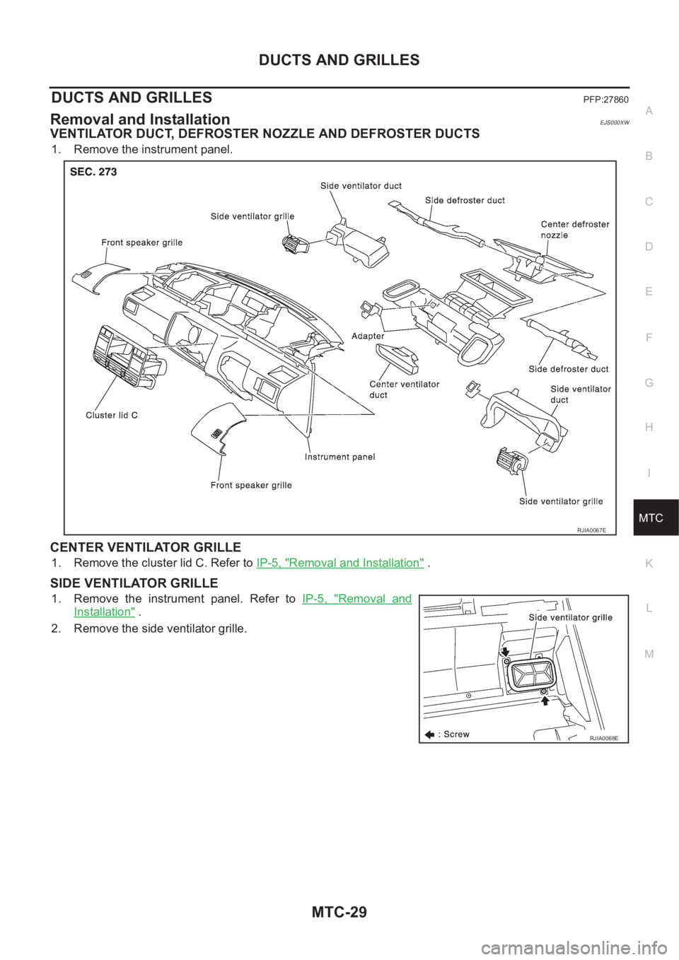
VENTILATOR DUCT, DEFROSTER NOZZLE AND DEFROSTER DUCTS
1. Remove the instrument panel.
CENTER VENTILATOR GRILLE
1. Remove the cluster lid C. Refer to IP-5, "Removal and Installation" .
SIDE VENTILATOR GRILLE
1. Remove the instrument panel. Refer to IP-5, "Removal and
Installation" .
2. Remove the side ventilator grille.
RJIA0067E
RJIA0068E
Page 3629 of 3833
WW-1
WIPER, WASHER & HORN
K ELECTRICAL
CONTENTS
C
D
E
F
G
H
I
J
L
M
SECTION
A
B
WW
WIPER, WASHER & HORN
PRECAUTIONS .......................................................... 3
Precautions for Supplemental Restraint System
(SRS) “AIR BAG” and “SEAT BELT PRE-TEN-
SIONER” .................................................................. 3
Wiring Diagrams and Trouble Diagnosis .................. 3
FRONT WIPER AND WASHER SYSTEM .................. 4
System Description .................................................. 4
WIPER OPERATION ............................................ 4
WASHER OPERATION ......................................... 4
Wiring Diagram — WIPER — .................................. 6
Terminal and Reference Values for Combination
Switch ....................................................................... 7
Removal and Installation for Front Wiper Arms,
Adjustment for Wiper Arms Stop Location ............... 7
Removal and Installation for Wiper Motor and Link-
age ........................................................................... 8
REMOVAL ............................................................. 9
INSTALLATION ..................................................... 9
Washer Nozzle Adjustment .................................... 10
Washer Tube Layout .............................................. 10
Removal and Installation for Washer Nozzle .......... 11
REMOVAL ............................................................ 11
INSTALLATION .................................................... 11
Inspection for Washer Nozzle ................................. 11
CHECK VALVE .................................................... 11
Removal and Installation for Wiper and Washer
Switch ...................................................................... 11
REMOVAL ............................................................ 11
INSTALLATION .................................................... 11
Removal and Installation for Washer Tank ............. 12
Removal and Installation for Washer Pump ........... 12
REAR WIPER AND WASHER SYSTEM .................. 13
Wiring Diagram — WIP/R — .................................. 13
Terminal and Reference Values for Combination
Switch ..................................................................... 15
Removal and Installation for Rear Wiper Arms ...... 15
WIPER ARMS ..................................................... 15
Removal and Installation for Wiper Motor and Link-
age ......................................................................... 16REMOVAL ........................................................... 16
INSTALLATION ................................................... 16
Washer Nozzle Adjustment .................................... 17
Removal and Installation for Rear Washer Nozzle ... 17
REMOVAL ........................................................... 17
INSTALLATION ................................................... 17
Inspection for Washer Nozzle ................................. 17
CHECK VALVE .................................................... 17
Removal and Installation for Wiper and Washer
Switch ..................................................................... 18
Removal and Installation for Washer Tank ............. 18
Removal and Installation for Washer Pump ........... 18
Washer Tube Layout .............................................. 18
HEADLAMP WASHER ............................................. 19
System Description ................................................. 19
Wiring Diagram –HLC– ........................................... 20
Removal and Installation for Washer Nozzle .......... 21
REMOVAL ........................................................... 21
INSTALLATION ................................................... 21
Inspection for Washer Nozzle ................................. 21
CHECK VALVE .................................................... 21
Removal and Installation for Washer Tank ............. 21
Removal and Installation for Washer Pump ........... 21
Washer Tube Layout .............................................. 22
HORN ........................................................................ 23
Wiring Diagram — HORN — .................................. 23
Removal and Installation ........................................ 24
REMOVAL ........................................................... 24
INSTALLATION ................................................... 24
CIGARETTE LIGHTER ............................................. 25
Wiring Diagram — CIGAR — ................................. 25
Removal and Installation ........................................ 26
REMOVAL ........................................................... 26
INSTALLATION ................................................... 26
POWER SOCKET ..................................................... 27
Wiring Diagram –POWER SOCKET– .................... 27
Removal and Installation for Front Power Socket ... 28
REMOVAL ........................................................... 28
Page 3638 of 3833
WW-10
FRONT WIPER AND WASHER SYSTEM
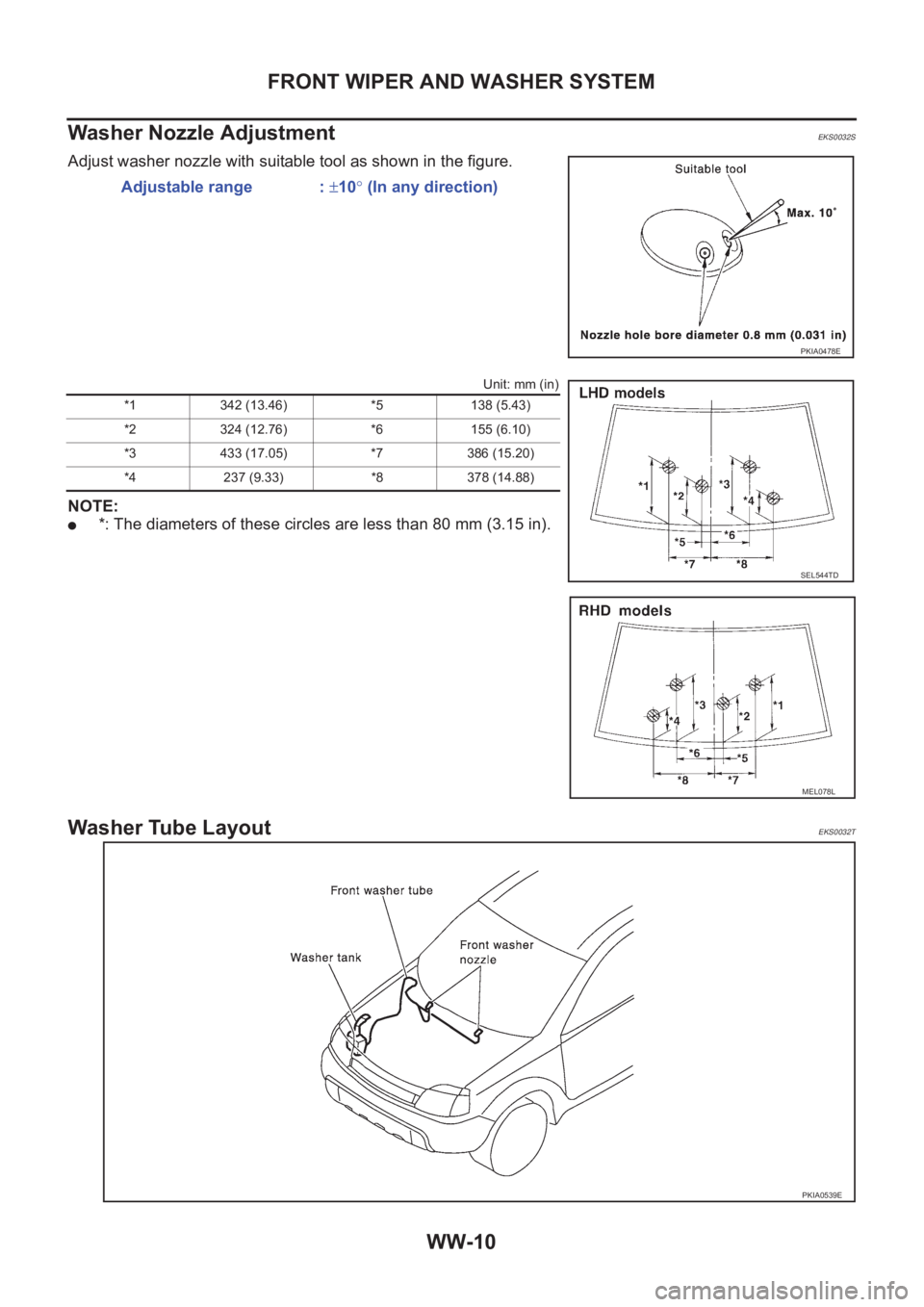
Washer Nozzle Adjustment
EKS0032S
Adjust washer nozzle with suitable tool as shown in the figure.
Unit: mm (in)
NOTE:
●*: The diameters of these circles are less than 80 mm (3.15 in).
Washer Tube LayoutEKS0032T
Adjustable range : ±10° (In any direction)
PKIA0478E
*1 342 (13.46) *5 138 (5.43)
*2 324 (12.76) *6 155 (6.10)
*3 433 (17.05) *7 386 (15.20)
*4 237 (9.33) *8 378 (14.88)
SEL544TD
MEL078L
PKIA0539E
Page 3639 of 3833
FRONT WIPER AND WASHER SYSTEM
WW-11
C
D
E
F
G
H
I
J
L
MA
B
WW
Removal and Installation for Washer Nozzle EKS0032U
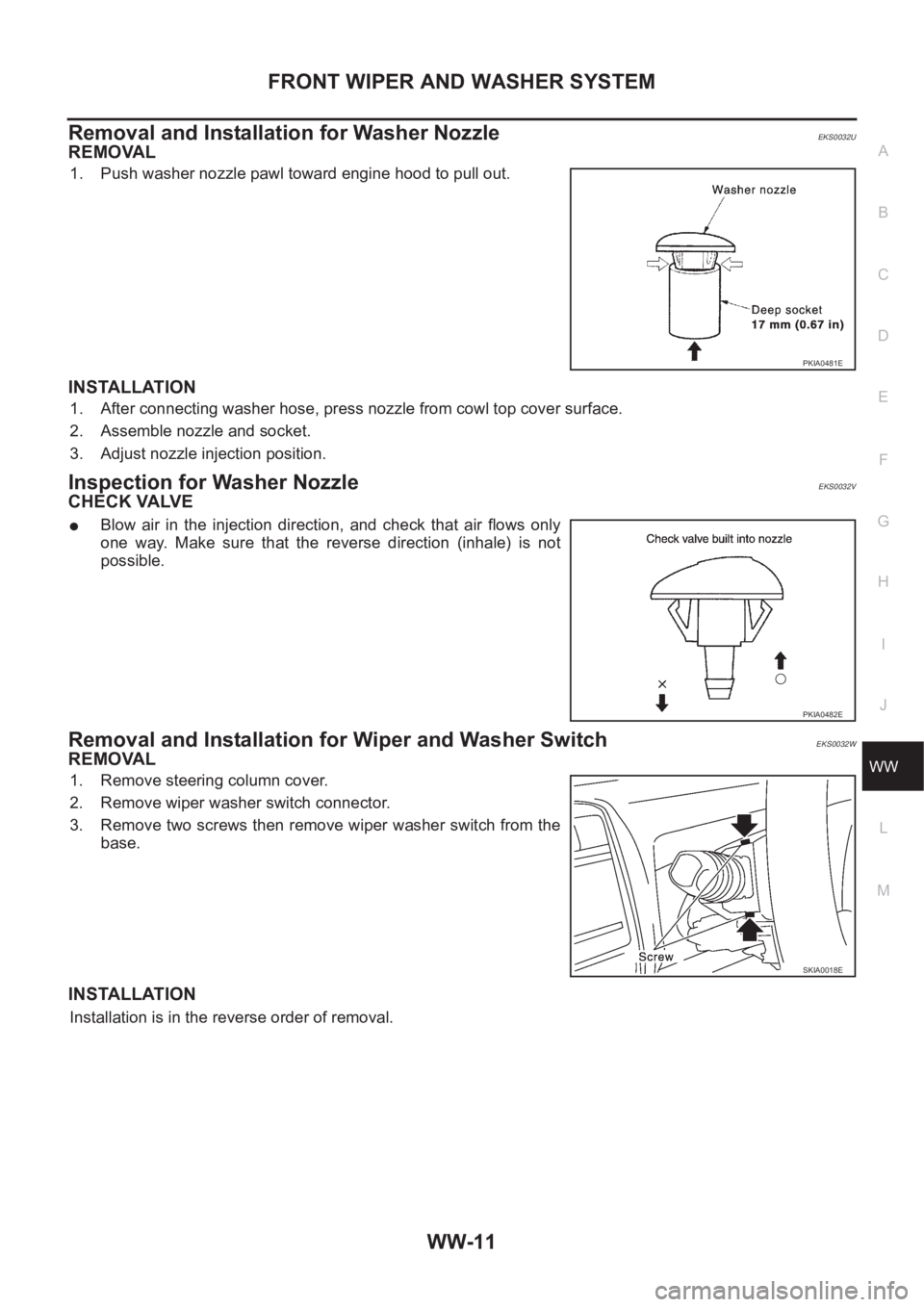
REMOVAL
1. Push washer nozzle pawl toward engine hood to pull out.
INSTALLATION
1. After connecting washer hose, press nozzle from cowl top cover surface.
2. Assemble nozzle and socket.
3. Adjust nozzle injection position.
Inspection for Washer Nozzle EKS0032V
CHECK VALVE
●Blow air in the injection direction, and check that air flows only
one way. Make sure that the reverse direction (inhale) is not
possible.
Removal and Installation for Wiper and Washer Switch EKS0032W
REMOVAL
1. Remove steering column cover.
2. Remove wiper washer switch connector.
3. Remove two screws then remove wiper washer switch from the
base.
INSTALLATION
Installation is in the reverse order of removal.
PKIA0481E
PKIA0482E
SKIA0018E
Page 3645 of 3833

REAR WIPER AND WASHER SYSTEM
WW-17
C
D
E
F
G
H
I
J
L
MA
B
WW
Washer Nozzle AdjustmentEKS00333
●Adjust washer nozzle with suitable tool as shown in the figure at left.
Unit: mm (in)
*: The diameter of this circle is less than 40 mm ( 1.57in).
Removal and Installation for Rear Washer Nozzle EKS00334
REMOVAL
1. Remove washer hose from washer nozzle.
2. Remove washer nozzle installation screw and remove washer
nozzle.
INSTALLATION
1. After connecting washer hose, press nozzle from cowl top cover surface.
2. Assemble nozzle and socket.
3. Adjust nozzle injection position.
Inspection for Washer Nozzle EKS00335
CHECK VALVE
●Blow air in the injection direction, and check that air flows only
one way. Make sure that the reverse direction (inhale) is not
possible. Adjustable range : ±10° (In any direction)
PKIA0487E
*H 90 (3.54)
* L 150 (5.91)
SKIA0091E
SKIA0085E
SKIA0042E
Page 3649 of 3833

HEADLAMP WASHER
WW-21
C
D
E
F
G
H
I
J
L
MA
B
WW
Removal and Installation for Washer NozzleEKS0036J
REMOVAL
1. Remove front bumper, refer toEI-6, "FRONT BUMPER"
2. Remove hose clip and washer nozzle metal clip.
3. Remove washer nozzle from front bumper.
INSTALLATION
Installation is in the reverse order of removal.
Inspection for Washer NozzleEKS0036K
CHECK VALVE
●Blow air in the injection direction, and check that air flows only
one way. Make sure that the reverse direction is not possible.
Removal and Installation for Washer TankEKS0036L
Refer to,WW-12, "Removal and Installation for Washer Tank"
Removal and Installation for Washer PumpEKS0036M
1. Remove front bumper, refer toEI-6, "FRONT BUMPER"
2. Remove washer pump connector and hose.
3. Pull out washer pump in the direction of the arrow in the figure,
and remove the washer pump from the washer tank.
CAUTION:
When installing washer pump, there should be no packing twist,
etc.
PKIA0490E
PKIA0491E
PKIA0494E
Page 3830 of 3833
IDX-6
ALPHABETICAL INDEX
EC-181,EC-536,EC-862,EC-901,EC-908,EC-917,
EC-1231
HO2S2 - Wiring diagram .... EC-187,EC-195,EC-310,
EC-318
,EC-923,EC-930,EC-1038,EC-1045
HO2S2H - Wiring diagram ................. EC-135,EC-867
Hood .................................................................... BL-4
Horn ................................................................. WW-23
HORN - Wiring diagram ................................... WW-23
How to erase DTC ......................................... EC-1406
How to erase DTC for OBD system .... EC-56,EC-455,
EC-788
,EC-1142
I
IATS - Wiring diagram ....................... EC-146
,EC-878
IATSEN - Wiring diagram ................ EC-668,EC-1317
Identification ..................................................... ATC-12
Idle air volume learning ........ EC-39,EC-450,EC-772,
EC-1137
Idle speed EC-73,EC-465,EC-805,EC-1152,EC-1412
IGN/SG - Wiring diagram ................. EC-380,EC-1075
Ignition coil ........ EC-379,EC-683,EC-1074,EC-1331
Ignition coil(QR20DE•QR25DE) ....................... EM-29
Ignition control system ..... EC-379,EC-683,EC-1074,
EC-1331
Ignition timing ........ EC-73,EC-465,EC-805,EC-1152
IGNSYS - Wiring diagram ................ EC-684,EC-1332
ILL - Wiring diagram ........................................... LT-45
Illumination .......................................................... LT-45
In vehicle sensor ........... ATC-102,ATC-104,ATC-113
INJECT - Wiring diagram . EC-389,EC-710,EC-1084,
EC-1358
,EC-1475
Injection nozzle(YD22DDTi) ........................... EM-144
Injector .............. EC-388,EC-709,EC-1083,EC-1357
Input shaft (FF M/T) .............................. MT-18,MT-23
Instrument panel ................................................... IP-3
INT/L - Wiring diagram ........................................ LT-65
Intake air temperature sensor ........... EC-144,EC-160,
EC-667
,EC-876,EC-1316
Intake door control linkage adjustment ............ ATC-69
Intake door motor ATC-68,ATC-119,MTC-11,MTC-23
Intake manifold(QR20DE•QR25DE) ................. EM-16
Intake manifold(YD22DDTi) ............................ EM-123
Intake sensor ................................ ATC-108,ATC-115
Intake valve timing control . EC-125,EC-699,EC-857,
EC-1347
Intake valve timing control solenoid valve ...... EC-271,
EC-699
,EC-1005,EC-1347
Interior ....................... EI-23,EI-25,EI-26,EI-28,EI-29
Interior lamp ........................................................ LT-55
Interior lamp on-off control ...................... LT-55,LT-56
ISO 15031-5 Mode 1 - 9 ...................... EC-44,EC-777
IVC - Wiring diagram ....................... EC-273,EC-1007
IVC/V - Wiring diagram .................... EC-701,EC-1349
J
Joint connector (J/C) ............................. PG-70
,PG-74
K
Keyless entry system - See Multi-remote control system
BL-55
Knock sensor (KS) EC-222,EC-546,EC-951,EC-1235
KS - Wiring diagram ........... EC-224,EC-548,EC-953,
EC-1237
L
LAN system circuit .......................................... ATC-59
License lamp ...................................................... LT-30
Line pressure solenoid valve ........................... AT-156
Line pressure test (A/T) ....................... AT-67,AT-268
Liquid gasket application(QR20DE•QR25DE) ... EM-6,
EM-111
,LU-3,LU-15,CO-3,CO-23
LOAD - Wiring diagram .... EC-416,EC-737,EC-1103,
EC-1377
Location of electrical units ................................ PG-63
Lock, door ............................................... BL-65,BL-68
Lubricant (R134a) A/C ........................ ATC-5,ATC-24
Lubrication circuit (engine)(QR20DE•QR25DE) .. LU-5
Lubrication circuit (engine)(YD22DDTi) ............. LU-17
Lubrication oil A/C ......................................... ATC-150
Lubrication-locks, hinges and hood latches ...... MA-41
M
M/T major overhaul ............................... MT-26
,MT-35
M/T oil replacement .......................................... MT-10
M/T removal and installation ............................. MT-15
MAFS - Wiring diagram ..... EC-140,EC-519,EC-872,
EC-1001
,EC-1205,EC-1453
Magnet clutch ................................. ATC-78,ATC-135
MAIN - Wiring diagram ...... EC-116,EC-507,EC-848,
EC-1193
,EC-1443
Mainshaft (M/T) ..................................... MT-18,MT-23
Maintenance (engine)(QR20DE•QR25DE) ....... MA-19
Maintenance (engine)(YD22DDTi) ................... MA-26
Malfunction indicator (MI) .. EC-263,EC-576,EC-991,
EC-1265
,EC-1407
Malfunction indicator lamp (MIL) ........ EC-58,EC-457,
EC-790
,EC-1144
Mass air flow sensor (MAFS) ........... EC-138,EC-516,
EC-870
,EC-999,EC-1202,EC-1451
Master cylinder (brake) ...................................... BR-13
Master cylinder (clutch) ........................................ CL-9
METER - Wiring diagram ........................... DI-8,DI-28
MIL - Wiring diagram ......... EC-264,EC-577,EC-992,
EC-1266
MIL/DL - Wiring diagram ................................ EC-1573
MIRROR - Wiring diagram ............................... GW-50
Mirror defogger ................................................ GW-15
Mirror, door ...................................................... GW-49
Mirror, out side ................................................. GW-49
Misfire ............................................... EC-217,EC-946
Mode door control linkage adjustment ........... ATC-64,
ATC-124
,MTC-9,MTC-27
Mode door motor ............................ ATC-62,ATC-124