air filter NISSAN X-TRAIL 2001 Service User Guide
[x] Cancel search | Manufacturer: NISSAN, Model Year: 2001, Model line: X-TRAIL, Model: NISSAN X-TRAIL 2001Pages: 3833, PDF Size: 39.49 MB
Page 367 of 3833
EC-17
C
D
E
F
G
H
I
J
K
L
M
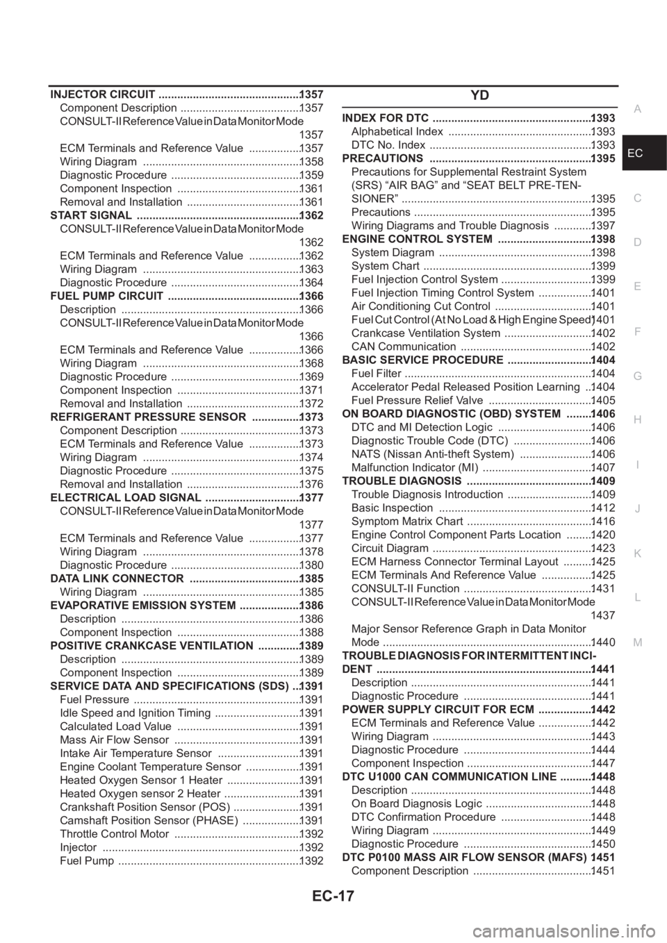
ECA INJECTOR CIRCUIT ..............................................1357
Component Description .......................................1357
CONSULT-II Reference Value in Data Monitor Mode
1357
ECM Terminals and Reference Value .................1357
Wiring Diagram ...................................................1358
Diagnostic Procedure ..........................................1359
Component Inspection ........................................1361
Removal and Installation .....................................1361
START SIGNAL .....................................................1362
CONSULT-II Reference Value in Data Monitor Mode
1362
ECM Terminals and Reference Value .................1362
Wiring Diagram ...................................................1363
Diagnostic Procedure ..........................................1364
FUEL PUMP CIRCUIT ...........................................1366
Description ..........................................................1366
CONSULT-II Reference Value in Data Monitor Mode
1366
ECM Terminals and Reference Value .................1366
Wiring Diagram ...................................................1368
Diagnostic Procedure ..........................................1369
Component Inspection ........................................1371
Removal and Installation .....................................1372
REFRIGERANT PRESSURE SENSOR ................1373
Component Description .......................................1373
ECM Terminals and Reference Value .................1373
Wiring Diagram ...................................................1374
Diagnostic Procedure ..........................................1375
Removal and Installation .....................................1376
ELECTRICAL LOAD SIGNAL ...............................1377
CONSULT-II Reference Value in Data Monitor Mode
1377
ECM Terminals and Reference Value .................1377
Wiring Diagram ...................................................1378
Diagnostic Procedure ..........................................1380
DATA LINK CONNECTOR ....................................1385
Wiring Diagram ...................................................1385
EVAPORATIVE EMISSION SYSTEM ....................1386
Description ..........................................................1386
Component Inspection ........................................1388
POSITIVE CRANKCASE VENTILATION ..............1389
Description ..........................................................1389
Component Inspection ........................................1389
SERVICE DATA AND SPECIFICATIONS (SDS) ...1391
Fuel Pressure ......................................................1391
Idle Speed and Ignition Timing ............................1391
Calculated Load Value ........................................1391
Mass Air Flow Sensor .........................................1391
Intake Air Temperature Sensor ...........................1391
Engine Coolant Temperature Sensor ..................1391
Heated Oxygen Sensor 1 Heater ........................1391
Heated Oxygen sensor 2 Heater .........................1391
Crankshaft Position Sensor (POS) ......................1391
Camshaft Position Sensor (PHASE) ...................1391
Throttle Control Motor ......................................... 1392
Injector ................................................................1392
Fuel Pump ...........................................................1392
YD
INDEX FOR DTC ....................................................1393
Alphabetical Index ...............................................1393
DTC No. Index .....................................................1393
PRECAUTIONS .....................................................1395
Precautions for Supplemental Restraint System
(SRS) “AIR BAG” and “SEAT BELT PRE-TEN-
SIONER” ..............................................................1395
Precautions ..........................................................1395
Wiring Diagrams and Trouble Diagnosis .............1397
ENGINE CONTROL SYSTEM ...............................1398
System Diagram ..................................................1398
System Chart .......................................................1399
Fuel Injection Control System ..............................1399
Fuel Injection Timing Control System ..................1401
Air Conditioning Cut Control ................................1401
F u e l C u t C o n t r o l ( A t N o L o a d & H i g h E n g i n e S p e e d ) 1401
Crankcase Ventilation System .............................1402
CAN Communication ...........................................1402
BASIC SERVICE PROCEDURE ............................1404
Fuel Filter .............................................................1404
Accelerator Pedal Released Position Learning ...1404
Fuel Pressure Relief Valve ..................................1405
ON BOARD DIAGNOSTIC (OBD) SYSTEM .........1406
DTC and MI Detection Logic ...............................1406
Diagnostic Trouble Code (DTC) ..........................1406
NATS (Nissan Anti-theft System) ........................1406
Malfunction Indicator (MI) ....................................1407
TROUBLE DIAGNOSIS .........................................1409
Trouble Diagnosis Introduction ............................1409
Basic Inspection ..................................................1412
Symptom Matrix Chart .........................................1416
Engine Control Component Parts Location .........1420
Circuit Diagram ....................................................1423
ECM Harness Connector Terminal Layout ..........1425
ECM Terminals And Reference Value .................1425
CONSULT-II Function ..........................................1431
CONSULT-II Reference Value in Data Monitor Mode
1437
Major Sensor Reference Graph in Data Monitor
Mode ....................................................................1440
TROUBLE DIAGNOSIS FOR INTERMITTENT INCI-
DENT ......................................................................1441
Description ...........................................................1441
Diagnostic Procedure ..........................................1441
POWER SUPPLY CIRCUIT FOR ECM ..................1442
ECM Terminals and Reference Value ..................1442
Wiring Diagram ....................................................1443
Diagnostic Procedure ..........................................1444
Component Inspection .........................................1447
DTC U1000 CAN COMMUNICATION LINE ...........1448
Description ...........................................................1448
On Board Diagnosis Logic ...................................1448
DTC Confirmation Procedure ..............................1448
Wiring Diagram ....................................................1449
Diagnostic Procedure ..........................................1450
DTC P0100 MASS AIR FLOW SENSOR (MAFS) .1451
Component Description .......................................1451
Page 393 of 3833

BASIC SERVICE PROCEDURE
EC-43
[QR25(WITH EURO-OBD)]
C
D
E
F
G
H
I
J
K
L
MA
EC
4. Install the fuel pressure gauge as shown in the figure.
●Wipe off oil or dirt from hose insertion part using cloth moist-
ened with gasoline.
●Apply proper amount of gasoline between top of the fuel tube
and No.1 spool.
●Insert fuel hose for fuel pressure check until it touches the
No.1 spool on fuel tube.
●Use NISSAN genuine hose clamp (part number: 16439
N4710 or 16439 40U00).
●When reconnecting fuel line, always use new clamps.
●When reconnecting fuel hose, check the original fuel hose for
damage and abnormality.
●Use a torque driver to tighten clamps.
●Install hose clamp to the position within 1 - 2 mm (0.04 - 0.08
in).
●Make sure that clamp screw does not contact adjacent parts.
5. After connecting fuel hose for fuel pressure check, pull the hose
with a force of approximately 98 N (10 kg, 22 lb) to confirm fuel
tube does not come off.
6. Turn ignition switch “ON”, and check for fuel leakage.
7. Start engine and check for fuel leakage.
8. Read the indication of fuel pressure gauge.
●Do not perform fuel pressure check with system operating. Fuel pressure gauge may indicate false
readings.
●During fuel pressure check, confirm for fuel leakage from fuel connection every 3 minutes.
9. If result is unsatisfactory, go to next step.
10. Check the following.
●Fuel hoses and fuel tubes for clogging
●Fuel filter for clogging
●Fuel pump
●Fuel pressure regulator for clogging
If OK, replace fuel pressure regulator.
If NG, repair or replace.Tightening torque: 1 - 1.5 N·m (0.1 - 0.15 kg-m,
9 - 13 in-lb)
At idling:
Approximately 350 kPa (3.5 bar, 3.57 kg/cm
2 , 51 psi)
PBIB0669E
PBIB0670E
Page 803 of 3833

BASIC SERVICE PROCEDURE
EC-453
[QR25(WITHOUT EURO-OBD)]
C
D
E
F
G
H
I
J
K
L
MA
EC
●Do not twist or kink fuel hose because it is plastic hose.
●Do not remove fuel hose from quick connector.
●Keep the original fuel hose to be free from intrusion of dust or foreign substances with a suitable cover.
4. Install the fuel pressure gauge as shown in the figure.
●Wipe off oil or dirt from hose insertion part using cloth moist-
ened with gasoline.
●Apply proper amount of gasoline between top of the fuel tube
and No.1 spool.
●Insert fuel hose for fuel pressure check until it touches the
No.1 spool on fuel tube.
●Use NISSAN genuine hose clamp (part number: 16439
N4710 or 16439 40U00).
●When reconnecting fuel line, always use new clamps.
●When reconnecting fuel hose, check the original fuel hose for
damage and abnormality.
●Use a torque driver to tighten clamps.
●Install hose clamp to the position within 1 - 2 mm (0.04 - 0.08
in).
●Make sure that clamp screw does not contact adjacent parts.
5. After connecting fuel hose for fuel pressure check, pull the hose
with a force of approximately 98 N (10 kg, 22 lb) to confirm fuel
tube does not come off.
6. Turn ignition switch “ON”, and check for fuel leakage.
7. Start engine and check for fuel leakage.
8. Read the indication of fuel pressure gauge.
●Do not perform fuel pressure check with system operating. Fuel pressure gauge may indicate false
readings.
●During fuel pressure check, confirm for fuel leakage from fuel connection every 3 minutes.
9. If result is unsatisfactory, go to next step.
10. Check the following.
●Fuel hoses and fuel tubes for clogging
●Fuel filter for clogging
●Fuel pump
●Fuel pressure regulator for clogging
If OK, replace fuel pressure regulator.
If NG, repair or replace.Tightening
torque: 1 - 1.5 N·m (0.1 - 0.15 kg-m, 9 - 13
in-lb)
At idling: Approximately 350 kPa (3.5 bar, 3.57 kg/cm
2 , 51
psi)
PBIB0669E
PBIB0670E
Page 1126 of 3833

EC-776
[QR20(WITH EURO-OBD)]
BASIC SERVICE PROCEDURE
4. Install the fuel pressure gauge as shown in the figure.
●Wipe off oil or dirt from hose insertion part using cloth moist-
ened with gasoline.
●Apply proper amount of gasoline between top of the fuel tube
and No.1 spool.
●Insert fuel hose for fuel pressure check until it touches the
No.1 spool on fuel tube.
●Use NISSAN genuine hose clamp (part number: 16439
N4710 or 16439 40U00).
●When reconnecting fuel line, always use new clamps.
●When reconnecting fuel hose, check the original fuel hose for
damage and abnormality.
●Use a torque driver to tighten clamps.
●Install hose clamp to the position within 1 - 2 mm (0.04 - 0.08
in).
●Make sure that clamp screw does not contact adjacent parts.
5. After connecting fuel hose for fuel pressure check, pull the hose
with a force of approximately 98 N (10 kg, 22 lb) to confirm fuel
tube does not come off.
6. Turn ignition switch “ON”, and check for fuel leakage.
7. Start engine and check for fuel leakage.
8. Read the indication of fuel pressure gauge.
●Do not perform fuel pressure check with system operating. Fuel pressure gauge may indicate false
readings.
●During fuel pressure check, confirm for fuel leakage from fuel connection every 3 minutes.
9. If result is unsatisfactory, go to next step.
10. Check the following.
●Fuel hoses and fuel tubes for clogging
●Fuel filter for clogging
●Fuel pump
●Fuel pressure regulator for clogging
If OK, replace fuel pressure regulator.
If NG, repair or replace.Tightening torque: 1 - 1.5 N·m (0.1 - 0.15 kg-m,
9 - 13 in-lb)
At idling:
Approximately 350 kPa (3.5 bar, 3.57 kg/cm
2 , 51 psi)
PBIB0669E
PBIB0670E
Page 1490 of 3833

EC-1140
[QR20(WITHOUT EURO-OBD)]
BASIC SERVICE PROCEDURE
●Do not twist or kink fuel hose because it is plastic hose.
●Do not remove fuel hose from quick connector.
●Keep the original fuel hose to be free from intrusion of dust or foreign substances with a suitable cover.
4. Install the fuel pressure gauge as shown in the figure.
●Wipe off oil or dirt from hose insertion part using cloth moist-
ened with gasoline.
●Apply proper amount of gasoline between top of the fuel tube
and No.1 spool.
●Insert fuel hose for fuel pressure check until it touches the
No.1 spool on fuel tube.
●Use NISSAN genuine hose clamp (part number: 16439
N4710 or 16439 40U00).
●When reconnecting fuel line, always use new clamps.
●When reconnecting fuel hose, check the original fuel hose for
damage and abnormality.
●Use a torque driver to tighten clamps.
●Install hose clamp to the position within 1 - 2 mm (0.04 - 0.08
in).
●Make sure that clamp screw does not contact adjacent parts.
5. After connecting fuel hose for fuel pressure check, pull the hose
with a force of approximately 98 N (10 kg, 22 lb) to confirm fuel
tube does not come off.
6. Turn ignition switch “ON”, and check for fuel leakage.
7. Start engine and check for fuel leakage.
8. Read the indication of fuel pressure gauge.
●Do not perform fuel pressure check with system operating. Fuel pressure gauge may indicate false
readings.
●During fuel pressure check, confirm for fuel leakage from fuel connection every 3 minutes.
9. If result is unsatisfactory, go to next step.
10. Check the following.
●Fuel hoses and fuel tubes for clogging
●Fuel filter for clogging
●Fuel pump
●Fuel pressure regulator for clogging
If OK, replace fuel pressure regulator.
If NG, repair or replace.Tightening
torque: 1 - 1.5 N·m (0.1 - 0.15 kg-m, 9 - 13
in-lb)
At idling: Approximately 350 kPa (3.5 bar, 3.57 kg/cm
2 , 51
psi)
PBIB0669E
PBIB0670E
Page 1754 of 3833

EC-1404
[YD]
BASIC SERVICE PROCEDURE
BASIC SERVICE PROCEDURE
PFP:00018
Fuel FilterEBS0036N
DESCRIPTION
A water draining cock is on the lower side and a priming pump for bleeding air is on the upper side.
AIR BLEEDING
Pump the priming pump to bleed air.
●When air is bled completely, the pumping of the priming pump
suddenly becomes heavy. Stop the operation at that time.
●If it is difficult to bleed air by the pumping of the priming pump
(the pumping of the priming pump does not become heavy), dis-
connect the fuel supply hose between the fuel filter and the fuel
gallery. Then, perform the operation described above, and make
sure that fuel comes out. (Use a pan, etc. so as not to spill fuel.
Do not let fuel get on engine and other parts.) After that, connect
the hose, then bleed air again.
●Start engine and let it idle for at least one minute after perform-
ing air bleeding.
WATER DRAINING
1. Remove the fuel filter, filter bracket, protector assembly from the dash panel as follows.
a. Remove the air cleaner case (upper), air duct assembly, and vacuum hose for brake booster (between the
vacuum pump and vacuum pipe).
CAUTION:
After the duct is removed, cover the opening with gum tape, etc. to prevent foreign object from
getting into the engine during the operation.
b. Remove the mounting nuts on the dash panel, then remove the fuel filter, filter bracket, and protector
assembly from the dash panel.
●It is not necessary to disconnect the fuel hose.
2. Using a tool such as a pliers, loosen the water draining cock at the bottom of the fuel filter.
Accelerator Pedal Released Position LearningEBS009NW
DESCRIPTION
"Accelerator Pedal Released Position Learning" is an operating to learn the fully released position of the
accelerator pedal by monitoring the accelerator pedal position sensor output signal. It must be performed
when accelerator work unit or ECM is replaced.
OPERATION PROCEDURE
1. Turn ignition switch "ON".
2. Select "OFF ACCEL PO SIG" in "ACTIVE TEST" mode with
CONSULT-II
3. Make sure that accelerator pedal is released.
SEF375Y
PBIB0411E
Page 1763 of 3833

TROUBLE DIAGNOSIS
EC-1413
[YD]
C
D
E
F
G
H
I
J
K
L
MA
EC
1.INSPECTION START
1. Check service records for any recent repairs that may indicate a related incident.
2. Check the current need for scheduled maintenance, especially for fuel filter and air cleaner filter. Refer to
MA-7, "
PERIODIC MAINTENANCE" .
3. Open engine hood and check the following:
–Harness connectors for improper connections
–Vacuum hoses for splits, kinks, or improper connections
–Wiring for improper connections, pinches, or cuts
4. Start engine and warm it up to the normal operating tempera-
ture.
>> GO TO 2.
2.PREPARATION FOR CHECKING IDLE SPEED
With CONSULT-II
Connect CONSULT-II to the data link connector.
>> GO TO 3.
3.CHECK IDLE SPEED
With CONSULT-II
1. Select “CKPS·RPM (TDC)” in “DATA MONITOR” mode with CONSULT-II.
2. Read idle speed.
OK or NG
OK >>INSPECTION END
NG >> GO TO 4.
4.CHECK FOR INTAKE AIR LEAK
Listen for an intake air leak after the mass air flow sensor.
OK or NG
OK >> GO TO 5.
NG >> Repair or replace.
SEF142I
725±25 rpm
SEF817Y
Page 1764 of 3833

EC-1414
[YD]
TROUBLE DIAGNOSIS
5. BLEED AIR FROM FUEL SYSTEM
1. Stop engine.
2. Use priming pump to bleed air from fuel system. Refer to EC-1404, "
AIR BLEEDING" .
>> GO TO 6.
6. CHECK IDLE SPEED AGAIN
With CONSULT-II
1. Start engine and let it idle.
2. Select “CKPS·RPM (TDC)” in “DATA MONITOR” mode with CONSULT-II.
3. Read idle speed.
OK or NG
OK >>INSPECTION END
NG >> GO TO 7.
7. DRAIN WATER FROM FUEL FILTER
Drain water from fuel filter. Refer to EC-1404, "
WATER DRAINING" .
>> GO TO 8.
8. CHECK IDLE SPEED AGAIN
With CONSULT-II
1. Start engine and let it idle.
2. Select “CKPS·RPM (TDC)” in “DATA MONITOR” mode with CONSULT-II.
3. Read idle speed.
OK or NG
OK >>INSPECTION END
NG >> GO TO 9.
9. CHECK AIR CLEANER FILTER
Check air cleaner filter for clogging or breaks.
OK or NG
OK >> GO TO 10.
NG >> Replace air cleaner filter.725±25 rpm
SEF817Y
725±25 rpm
SEF817Y
Page 1925 of 3833

FL-1
FUEL SYSTEM
B ENGINE
CONTENTS
C
D
E
F
G
H
I
J
K
L
M
SECTION
A
FL
FUEL SYSTEM
QR
PREPARATION ........................................................... 2
Commercial Service Tool ......................................... 2
FUEL SYSTEM ........................................................... 3
Checking Fuel Lines ............................................ ..... 3
General Precautions ................................................ 3
FUEL LEVEL SENSOR UNIT, FUEL FILTER AND
FUEL PUMP ASSEMBLY ........................................... 4
Removal and Installation .......................................... 4
REMOVAL ............................................................. 4
INSPECTION AFTER REMOVAL ......................... 6
INSTALLATION ..................................................... 6
INSPECTION AFTER INSTALLATION ................. 6
Disassembly and Assembly ..................................... 7
DISASSEMBLY ..................................................... 7
ASSEMBLY ........................................................... 8
FUEL TANK ................................................................ 9
Removal and Installation .......................................... 9
REMOVAL ............................................................. 9
INSTALLATION ................................................... 10
INSPECTION AFTER INSTALLATION ................ 11
SERVICE DATA AND SPECIFICATIONS (SDS) ...... 12
Standard and Limit ................................................. 12
FUEL TANK ......................................................... 12
Tightening Torque ................................................... 12
YD22DDTi
PREPARATION ......................................................... 13
Commercial Service Tool ........................................ 13
FUEL SYSTEM ......................................................... 14
Checking Fuel Lines ............................................ ... 14
General Precautions ............................................... 14
FUEL FILTER ............................................................ 15
Removal and Installation ........................................ 15
REMOVAL ........................................................... 15
INSTALLATION ................................................... 15
INSPECTION AFTER INSTALLATION ................ 15
Air Bleeding ............................................................ 16
Draining Water from Fuel Filter .............................. 16
FUEL LEVEL SENSOR UNIT ................................... 17
Removal and Installation ........................................ 17
REMOVAL ........................................................... 17
INSPECTION AFTER REMOVAL ....................... 19
INSTALLATION ................................................... 19
INSPECTION AFTER INSTALLATION ................ 20
FUEL TANK .............................................................. 21
Removal and Installation ........................................ 21
REMOVAL ........................................................... 21
INSTALLATION ................................................... 22
INSPECTION AFTER INSTALLATION ................ 22
SERVICE DATA AND SPECIFICATIONS (SDS) ...... 24
Standard and Limit .................................................. 24
Tightening Torque ................................................... 24
Page 1939 of 3833

FUEL FILTER
FL-15
[YD22DDTi]
C
D
E
F
G
H
I
J
K
L
MA
FL
FUEL FILTERPFP:16400
Removal and InstallationEBS00BLA
REMOVAL
1. Remove air duct and upper air cleaner case.
2. Remove fuel filter protector.
3. Disconnect fuel hoses at fuel filter bracket.
CAUTION:
Plug the pipe to prevent fuel from draining.
4. Remove fuel filter with bracket.
CAUTION:
Do not splash fuel during removal. If fuel is splashed,
immediately wipe it off.
5. Using band-type filter wrench (commercial service tool), remove
fuel filter.
6. Turn fuel filter upside down to drain fuel.
7. Remove drain plug from fuel filter.
INSTALLATION
Install in reverse order of removal, paying attention to following:
●Replace O-ring on drain plug with new one.
●Screw the fuel filter by hand until packing contacts sealing surface of bracket. Then tighten it by turning
approximately 2/3 turn.
●After installation, bleed air from fuel path. Refer to FL-16, "Air Bleeding" .
INSPECTION AFTER INSTALLATION
Make sure there is no fuel leakage at connections in the following steps.
1. Apply fuel pressure to fuel lines with turning ignition switch “ON” (with engine stopped). Then check for
fuel leaks at connections.
2. Start the engine and rev it up and check for fuel leaks at connections.
SBIA0134E
SBIA0135E
SBIA0136E
Drain plug
: 3.9 - 5.9 N·m (0.4 - 0.6 kg-m, 35 - 52 in-lb)