flywheel NISSAN X-TRAIL 2001 Service User Guide
[x] Cancel search | Manufacturer: NISSAN, Model Year: 2001, Model line: X-TRAIL, Model: NISSAN X-TRAIL 2001Pages: 3833, PDF Size: 39.49 MB
Page 269 of 3833

CYLINDER BLOCK
EM-219
[YD22DDTi]
C
D
E
F
G
H
I
J
K
L
MA
EM
2. Put a mating mark on circumferences of the two flywheel
masses without applying any load (Measurement standard
points).
3. Apply a force of 9.8 N·m (1 kg-m, 87 in-lb) in each direction, and
mark the movement amount on the mass on the transaxle side.
4. Measure dimensions of movement amounts A and B on circum-
ference of the flywheel on the transaxle side.
●When measured value is outside the standard, replace fly-
wheel.Standard : 26.2 mm (1.031 in) or less
PBIC1258E
Page 278 of 3833

EM-228
[YD22DDTi]
SERVICE DATA AND SPECIFICATIONS (SDS)
AVAILABLE MAIN BEARING
Main bearing
Unit: mm (in)
Under size
Unit: mm (in)
AVAILABLE CONNECTING ROD BEARING
Connecting Rod Bearing
Unit: mm (in)
Under size
Unit: mm (in)
MISCELLANEOUS COMPONENTS
Flywheel
Unit: mm (in)
*: Total indicator reading Grade number Thickness “T” Width “W” Identification color
0 1.816 - 1.820 (0.0715 - 0.0717)
19.9 - 20.1 (0.783 - 0.791)Black
1 1.820 - 1.824 (0.0717 - 0.0718) Brown
2 1.824 - 1.828 (0.0718 - 0.0720) Green
3 1.828 - 1.832 (0.0720 - 0.0721) Yellow
4 1.832 - 1.836 (0.0721 - 0.0723) Blue
SEM255G
Size Thickness Main journal diameter “Dm”
0.25 (0.0098) 1.949 - 1.953 (0.0767 - 0.0769)Grind so that bearing clearance is the
specified value.
Grade number Thickness “T” Width “W” Identification color (mark)
0 1.492 - 1.496 (0.0587 - 0.0589)
22.9 - 23.1
(0.902 - 0.909)Black
1 1.496 - 1.500 (0.0589 - 0.0591) Brown
2 1.500 - 1.504 (0.0591 - 0.0592) Green
Size Thickness Crank pin journal diameter “Dp”
0.08 (0.0031) 1.536 - 1.540 (0.0605 - 0.0606)
Grind so that bearing clearance is the
specified value. 0.12 (0.0047) 1.556 - 1.560 (0.0613 - 0.0614)
0.25 (0.0098) 1.621 - 1.625 (0.0638 - 0.0640)
Flywheel runout [TIR]*Standard 0.45 (0.0177) or less
Limit 1.3 (0.051) or less
Page 280 of 3833

EM-230
[YD22DDTi]
SERVICE DATA AND SPECIFICATIONS (SDS)
Common rail51.0 - 64.0 (5.2 - 6.5, 38 - 47)
Fuel supply pump51.0 - 56.0 (5.2 - 5.7, 38 - 41)
Fuel supply pump sprocket 37.0 - 41.0 (3.8 - 4.2, 28 - 30)
Fuel supply pump rear bracket 27.0 - 37.0 (2.8 - 3.8, 20 - 27)
Front chain case
6.9 - 8.8 (0.7 - 0.9, 61 - 78)*
2
Chain tensioner
8.5 - 10.7 (0.86 - 1.1, 75 - 95)*2
Tension guide21.0 - 26.0 (2.1 - 2.7, 16 - 19)
Slack guide21.0 - 26.0 (2.1 - 2.7, 16 - 19)
Camshaft sprocket 138 - 147 (14.0 - 15.0, 102 - 108)
Fuel supply pump sprocket 38.0 - 41.0 (3.8 - 4.2, 28 - 30)
Oil pump12.0 - 13.0 (1.3 - 1.4, 9 - 10)
Power steering pump51.0 - 56.0 (5.2 - 5.8, 38 - 41)
Rear chain case12.0 - 13.0 (1.2 - 1.4, 19 - 10)
Engine coolant temperature sensor 12.0 - 15.0 (1.2 - 1.6, 9 - 11)
*1 Cylinder head 1) 29 - 38 (2.9 - 3.9, 21 - 28)
2) 180° to 185°
3) 0 (0, 0)
4) 35 to 44 (3.5 - 4.5, 26 - 32)
5) 90° to 95°(angle tightening)
6) 90° to 95° (angle tightening)
Water outlet21 - 28 (2.1 - 2.9, 16 - 20)
Glow plug18.0 - 21.0 (1.8 - 2.2, 13 - 15)
*1 Flywheel103 - 112 (10.5 - 11.5, 76 - 83)
Oil pressure switch13.0 - 17.0 (1.25 - 1.75, 9 - 12)
Oil jet6.1 - 10.7(0.62 - 1.1, 54 - 95)
Oil jet relief valve40 - 58 (4.0 - 6.0, 29 - 43)
Rear oil seal retainer12.0 - 13.0 (1.2 - 1.4, 9 - 10)
Page 567 of 3833

DTC P0300 - P0304 MULTIPLE CYLINDER MISFIRE, NO. 1 - 4 CYLINDER MIS-
FIRE
EC-217
[QR25(WITH EURO-OBD)]
C
D
E
F
G
H
I
J
K
L
MA
EC
DTC P0300 - P0304 MULTIPLE CYLINDER MISFIRE, NO. 1 - 4 CYLINDER MIS-
FIRE
PFP:00000
On Board Diagnosis LogicEBS00M52
When a misfire occurs, engine speed will fluctuate. If the engine speed fluctuates enough to cause the crank-
shaft position (CKP) sensor (POS) signal to vary, ECM can determine that a misfire is occurring.
The misfire detection logic consists of the following two conditions.
1. One Trip Detection Logic (Three Way Catalyst Damage)
On the first trip that a misfire condition occurs that can damage the three way catalyst (TWC) due to over-
heating, the MI will blink.
When a misfire condition occurs, the ECM monitors the CKP sensor (POS) signal every 200 engine revo-
lutions for a change.
When the misfire condition decreases to a level that will not damage the TWC, the MI will turn off.
If another misfire condition occurs that can damage the TWC on a second trip, the MI will blink.
When the misfire condition decreases to a level that will not damage the TWC, the MI will remain on.
If another misfire condition occurs that can damage the TWC, the MI will begin to blink again.
2. Two Trip Detection Logic (Exhaust quality deterioration)
For misfire conditions that will not damage the TWC (but will affect vehicle emissions), the MI will only light
when the misfire is detected on a second trip. During this condition, the ECM monitors the CKP sensor
signal every 1,000 engine revolutions.
A misfire malfunction can be detected on any one cylinder or on multiple cylinders.
DTC Confirmation ProcedureEBS00M53
CAUTION:
Always drive vehicle at a safe speed.
NOTE:
If “DTC Confirmation Procedure” has been previously conducted, always turn ignition switch “OFF” and wait at
least 10 seconds before conducting the next test.
WITH CONSULT-II
1. Turn ignition switch “ON”, and select “DATA MONITOR” mode with CONSULT-II.
2. Start engine and warm it up to normal operating temperature.
3. Turn ignition switch “OFF” and wait at least 10 seconds.
Sensor Input Signal to ECM ECM function
Crankshaft position sensor (POS) Engine speed On board diagnosis of misfire
DTC No. Trouble diagnosis name DTC detecting condition Possible cause
P0300
0300Multiple cylinder misfire
detectedMultiple cylinder misfire.
●Improper spark plug
●Insufficient compression
●Incorrect fuel pressure
●The injector circuit is open or shorted
●Fuel injectors
●Intake air leak
●The ignition signal circuit is open or
shorted
●Lack of fuel
●Drive plate or flywheel
●Heated oxygen sensor 1 P0301
0301No.1 cylinder misfire
detectedNo. 1 cylinder misfires.
P0302
0302No. 2 cylinder misfire
detectedNo. 2 cylinder misfires.
P0303
0303No. 3 cylinder misfire
detectedNo. 3 cylinder misfires.
P0304
0304No. 4 cylinder misfire
detectedNo. 4 cylinder misfires.
Page 1296 of 3833

EC-946
[QR20(WITH EURO-OBD)]
DTC P0300 - P0304 MULTIPLE CYLINDER MISFIRE, NO. 1 - 4 CYLINDER MIS-
FIRE
DTC P0300 - P0304 MULTIPLE CYLINDER MISFIRE, NO. 1 - 4 CYLINDER MIS-
FIRE
PFP:00000
On Board Diagnosis LogicEBS00MWX
When a misfire occurs, engine speed will fluctuate. If the engine speed fluctuates enough to cause the crank-
shaft position (CKP) sensor (POS) signal to vary, ECM can determine that a misfire is occurring.
The misfire detection logic consists of the following two conditions.
1. One Trip Detection Logic (Three Way Catalyst Damage)
On the first trip that a misfire condition occurs that can damage the three way catalyst (TWC) due to over-
heating, the MI will blink.
When a misfire condition occurs, the ECM monitors the CKP sensor (POS) signal every 200 engine revo-
lutions for a change.
When the misfire condition decreases to a level that will not damage the TWC, the MI will turn off.
If another misfire condition occurs that can damage the TWC on a second trip, the MI will blink.
When the misfire condition decreases to a level that will not damage the TWC, the MI will remain on.
If another misfire condition occurs that can damage the TWC, the MI will begin to blink again.
2. Two Trip Detection Logic (Exhaust quality deterioration)
For misfire conditions that will not damage the TWC (but will affect vehicle emissions), the MI will only light
when the misfire is detected on a second trip. During this condition, the ECM monitors the CKP sensor
signal every 1,000 engine revolutions.
A misfire malfunction can be detected on any one cylinder or on multiple cylinders.
DTC Confirmation ProcedureEBS00MWY
CAUTION:
Always drive vehicle at a safe speed.
NOTE:
If “DTC Confirmation Procedure” has been previously conducted, always turn ignition switch “OFF” and wait at
least 10 seconds before conducting the next test.
WITH CONSULT-II
1. Turn ignition switch “ON”, and select “DATA MONITOR” mode with CONSULT-II.
2. Start engine and warm it up to normal operating temperature.
3. Turn ignition switch “OFF” and wait at least 10 seconds.
Sensor Input Signal to ECM ECM function
Crankshaft position sensor (POS) Engine speed On board diagnosis of misfire
DTC No. Trouble diagnosis name DTC detecting condition Possible cause
P0300
0300Multiple cylinder misfire
detectedMultiple cylinder misfire.
●Improper spark plug
●Insufficient compression
●Incorrect fuel pressure
●The injector circuit is open or shorted
●Fuel injectors
●Intake air leak
●The ignition signal circuit is open or
shorted
●Lack of fuel
●Drive plate or flywheel
●Heated oxygen sensor 1 P0301
0301No.1 cylinder misfire
detectedNo. 1 cylinder misfires.
P0302
0302No. 2 cylinder misfire
detectedNo. 2 cylinder misfires.
P0303
0303No. 3 cylinder misfire
detectedNo. 3 cylinder misfires.
P0304
0304No. 4 cylinder misfire
detectedNo. 4 cylinder misfires.
Page 1959 of 3833

CL-1
CLUTCH
C TRANSMISSION/TRANSAXLE
CONTENTS
D
E
F
G
H
I
J
K
L
M
SECTION
A
B
CL
CLUTCH
PRECAUTIONS .......................................................... 2
Caution ..................................................................... 2
PREPARATION ........................................................... 3
Special Service Tools ............................................... 3
NOISE, VIBRATION, AND HARSHNESS (NVH)
TROUBLESHOOTING ................................................ 4
NVH Troubleshooting Chart ..................................... 4
CLUTCH ................................................................ 4
CLUTCH PEDAL ........................................................ 5
On-Vehicle Inspection and Adjustment .................... 5
HEIGHT ADJUSTMENT ....................................... 5
CLUTCH SWITCH POSITION ADJUSTMENT ..... 5
FREE PLAT INSPECTION .................................... 6
CLEARANCE CHECK ........................................... 6
Removal and Installation .......................................... 6
INSPECTION AFTER REMOVAL ......................... 7
CLUTCH FLUID .......................................................... 8
Air Bleeding Procedure ............................................ 8
CLUTCH MASTER CYLINDER .................................. 9
Removal and Installation .......................................... 9
REMOVAL ........................................................... 10
INSTALLATION ................................................... 10
Disassembly and Assembly ................................... 10
DISASSEMBLY ................................................... 10
INSPECTION AFTER DISASSEMBLY ............... 10
ASSEMBLY ......................................................... 10
OPERATING CYLINDER ...........................................11Removal and Installation ........................................ 11
REMOVAL ........................................................... 11
INSTALLATION ................................................... 11
Disassembly and Assembly .................................... 11
DISASSEMBLY ................................................... 11
INSPECTION AFTER DISASSEMBLY ................ 11
ASSEMBLY ......................................................... 11
CLUTCH PIPING ....................................................... 12
Removal and Installation ........................................ 12
CLUTCH RELEASE MECHANISM ........................... 13
Removal and Installation ........................................ 13
REMOVAL ........................................................... 13
INSPECTION AFTER REMOVAL ....................... 13
INSTALLATION ................................................... 13
CLUTCH DISC, CLUTCH COVER AND FLYWHEEL ... 15
Removal and Installation ........................................ 15
REMOVAL ........................................................... 15
INSPECTION AND ADJUSTMENT AFTER
REMOVAL ........................................................... 16
INSTALLATION ................................................... 17
SERVICE DATA AND SPECIFICATIONS (SDS) ...... 18
Clutch Control System ............................................ 18
Clutch Master Cylinder ........................................... 18
Clutch Operating Cylinder ...................................... 18
Clutch Disc ............................................................. 18
Clutch Cover ........................................................... 18
Clutch Pedal ........................................................... 18
Page 1962 of 3833
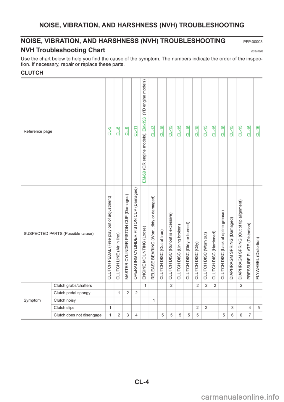
CL-4
NOISE, VIBRATION, AND HARSHNESS (NVH) TROUBLESHOOTING
NOISE, VIBRATION, AND HARSHNESS (NVH) TROUBLESHOOTING
PFP:00003
NVH Troubleshooting ChartECS008B8
Use the chart below to help you find the cause of the symptom. The numbers indicate the order of the inspec-
tion. If necessary, repair or replace these parts.
CLUTCH
Reference pageCL-5CL-8CL-9CL-11
EM-69
(QR engine models), EM-193
(YD engine models)
CL-13
CL-15CL-15CL-15CL-15CL-15CL-15CL-15CL-15CL-15CL-15CL-15CL-16
SUSPECTED PARTS (Possible cause)
CLUTCH PEDAL (Free play out of adjustment)
CLUTCH LINE (Air in line)
MASTER CYLINDER PISTON CUP (Damaged)
OPERATING CYLINDER PISTON CUP (Damaged)
ENGINE MOUNTING (Loose)
RELEASE BEARING (Worn, dirty or damaged)
CLUTCH DISC (Out of true)
CLUTCH DISC (Runout is excessive)
CLUTCH DISC (Lining broken)
CLUTCH DISC (Dirty or burned)
CLUTCH DISC (Oily)
CLUTCH DISC (Worn out)
CLUTCH DISC (Hardened)
CLUTCH DISC (Lack of spline grease)
DIAPHRAGM SPRING (Damaged)
DIAPHRAGM SPRING (Out of tip alignment)
PRESSURE PLATE (Distortion)
FLYWHEEL (Distortion)
SymptomClutch grabs/chatters 1 2 2 2 2 2
Clutch pedal spongy 1 2 2
Clutch noisy 1
Clutch slips 1 2 2 3 4 5
Clutch does not disengage 1 2 3 4 5 5 5 5 5 5 6 6 7
Page 1971 of 3833

CLUTCH RELEASE MECHANISM
CL-13
D
E
F
G
H
I
J
K
L
MA
B
CL
CLUTCH RELEASE MECHANISMPFP:30502
Removal and InstallationECS008BF
REMOVAL
1. Remove manual transaxle from the vehicle.
●Refer to MT-15, "Removal and Installation" .
2. Remove release bearing, holder spring, and withdrawal lever from inside the clutch housing.
3. Remove dust cover.
4. Remove retainer spring from the withdrawal lever.
INSPECTION AFTER REMOVAL
●If release bearing is seized, damaged, not properly centered or
does not rotate smoothly, replace it.
●If contact surface of the withdrawal lever is excessively worn,
replace it.
●If dust cover is cracked, replace it.
INSTALLATION
CAUTION:
●Be sure to apply grease to the points specified. Otherwise, noise, poor disengagement, or damage
to the clutch may result. Excessive grease may cause slip or quiver. Wipe off any grease oozing
from the parts.
●Be careful not to bring any grease into contact with the clutch disk facing, pressure plate surface,
or flywheel surface.
SCIA0328E
SCL733
Page 1973 of 3833

CLUTCH DISC, CLUTCH COVER AND FLYWHEEL
CL-15
D
E
F
G
H
I
J
K
L
MA
B
CL
CLUTCH DISC, CLUTCH COVER AND FLYWHEELPFP:30100
Removal and InstallationECS008BG
—QR engine models—
—YD engine models—
CAUTION:
Be careful not to bring any grease into contact with the clutch disc facing, pressure plate surface, or
flywheel surface.
REMOVAL
1. Remove manual transaxle from the vehicle.
●Refer to MT-15, "Removal and Installation" .
2. Loosen clutch cover mounting bolts evenly. Remove clutch cover and clutch disc.
SCIA0329E
SCIA0813E
Page 1974 of 3833

CL-16
CLUTCH DISC, CLUTCH COVER AND FLYWHEEL
INSPECTION AND ADJUSTMENT AFTER REMOVAL
Clutch Disc
●Measure circumferential runout relative to the clutch disc center
spline. If it is outside the specification, replace the clutch disc.
●Measure clutch disc spline and input shaft spline backlash at the
circumference of the disc. If outside the specification, replace.
●Using calipers, measure the depth to the clutch disc facing rivet
heads. If it exceeds the allowable wear limit, replace the clutch
disc.
Clutch Cover
Check diaphragm spring lever claws for unevenness with the lever
still on the vehicle. If they exceed the tolerance, adjust lever height
using a diaphragm adjusting wrench (special service tool).
●Check clutch cover thrust ring for wear or breakage. If wear or
breakage is found, replace clutch cover assembly.
NOTE:
●Worn thrust ring will generate a beating noise when tapped at
the rivet with a hammer.
●Broken thrust ring will make a clinking sound when cover is
shaken up and down.
●If a trace of burn or discoloration is found on the clutch cover pressure plate to clutch disc contact surface,
repair the surface with sandpaper. If surface is damaged or distorted, replace the assembly.
Flywheel Runout
Using a dial gauge, measure runout at the flywheel clutch contact
surface. If runout is outside the specification, replace the flywheel. If
a trace of burn or discoloration is found on the surface, repair it with
sandpaper.
CAUTION:
Measure it at flywheel outer face (not on knock pin and clutch cover mounting hole). Runout limit/diameter of the area to be measured:
1.0 mm (0.039 in) or less/230 mm(9.06 in) dia.
Maximum allowable spline backlash:
1.0 mm (0.039 in)
SCL221
Facing wear limit (depth to the rivet head):
0.3 mm (0.012 in)
SCL229
Tolerance for diaphragm spring lever unevenness:
0.7 mm (0.028 in)
SCL466-C
Allowable flywheel runout:
Vehicles with QR engine models:
Refer to EM-97, "
Flywheel Deflection" .
Vehicles with YD engine models:
Refer to EM-218, "
Flywheel Deflection" .AEM100