manual transmission NISSAN X-TRAIL 2001 Service User Guide
[x] Cancel search | Manufacturer: NISSAN, Model Year: 2001, Model line: X-TRAIL, Model: NISSAN X-TRAIL 2001Pages: 3833, PDF Size: 39.49 MB
Page 2087 of 3833
PREPARATION
AT-9
D
E
F
G
H
I
J
K
L
MA
B
AT
PREPARATIONPFP:00100
Special Service ToolsECS004Q5
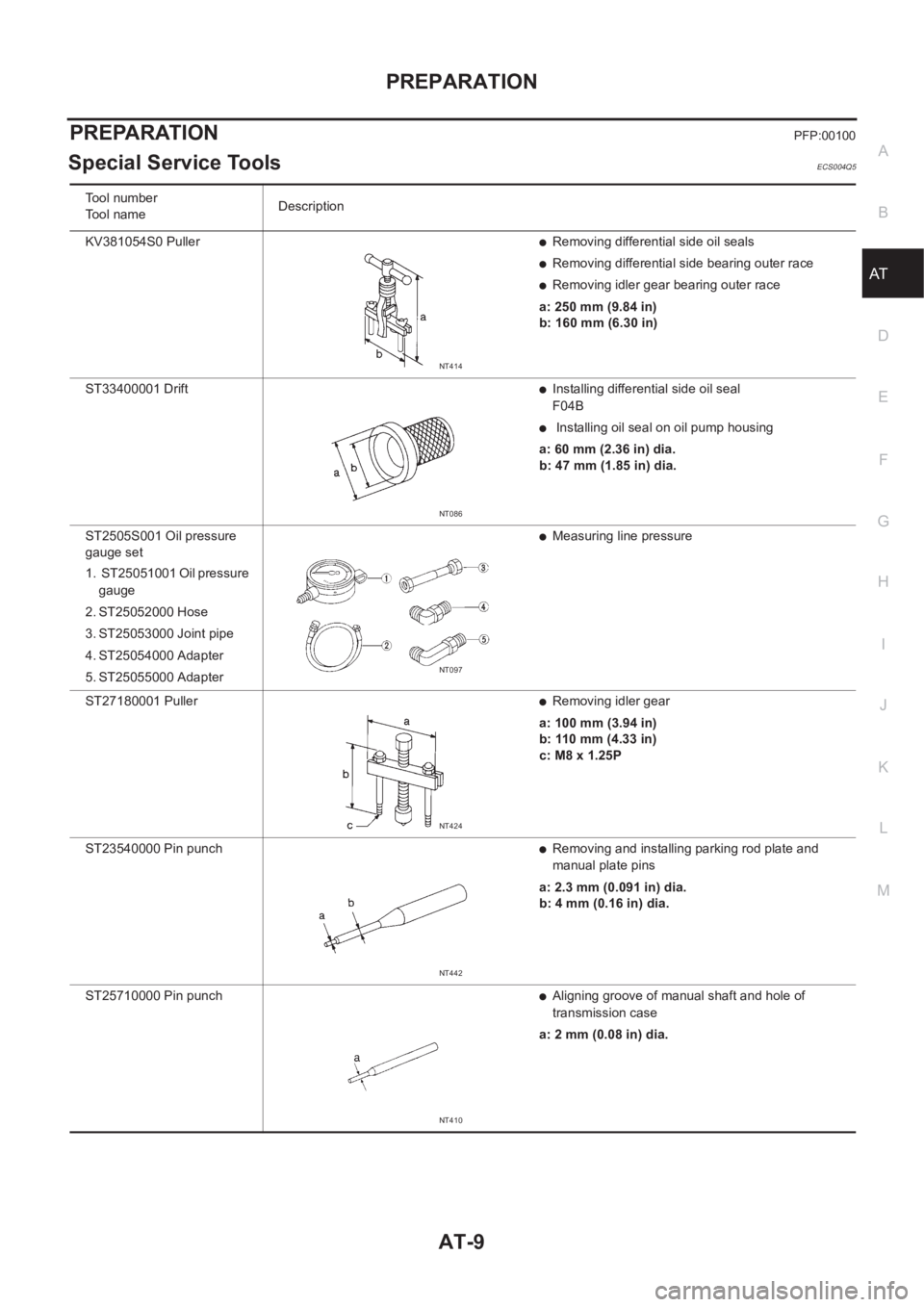
Tool number
Tool nameDescription
KV381054S0 Puller
●Removing differential side oil seals
●Removing differential side bearing outer race
●Removing idler gear bearing outer race
a: 250 mm (9.84 in)
b: 160 mm (6.30 in)
ST33400001 Drift
●Installing differential side oil seal
F04B
● Installing oil seal on oil pump housing
a: 60 mm (2.36 in) dia.
b: 47 mm (1.85 in) dia.
ST2505S001 Oil pressure
gauge set
1. ST25051001 Oil pressure
gauge
2. ST25052000 Hose
3. ST25053000 Joint pipe
4. ST25054000 Adapter
5. ST25055000 Adapter
●Measuring line pressure
ST27180001 Puller
●Removing idler gear
a: 100 mm (3.94 in)
b: 110 mm (4.33 in)
c: M8 x 1.25P
ST23540000 Pin punch
●Removing and installing parking rod plate and
manual plate pins
a: 2.3 mm (0.091 in) dia.
b: 4 mm (0.16 in) dia.
ST25710000 Pin punch
●Aligning groove of manual shaft and hole of
transmission case
a: 2 mm (0.08 in) dia.
NT414
NT086
NT097
NT424
NT442
NT410
Page 2493 of 3833

ON-VEHICLE SERVICE
AT-415
[ALL]
D
E
F
G
H
I
J
K
L
MA
B
AT
6. Remove control valve assembly by removing fixing bolts.
Bolt length, number and location:
●Be careful not to drop manual valve and servo release accumulator return springs.
7. Disassemble and inspect control valve assembly if necessary. Refer to AT- 4 1 4 , "
Control Valve Assembly
and Accumulators" .
8. Remove servo release and N-D accumulators by applying com-
pressed air if necessary.
●Hold each piston with a rag.
INSTALLATION
●Tighten fixing bolts to specification.
●Set manual shaft in Neutral position, then align manual
plate with groove in manual valve.
●After installing control valve assembly to transmission
case, make sure that selector lever can be moved to all
positions.
AAT260A
Bolt symbol A B C
Bolt length “ ” mm(in)40.0 mm
(1.575 in)33.0 mm
(1.299 in)43.5 mm
(1.713 in)
Number of bolts 5 6 2
SAT935J
: 7 - 9 N-m (0.7 - 0.9 kg-m, 61 - 78 in-lb)
SAT497H
Page 2506 of 3833

AT-428
[ALL]
DISASSEMBLY
c. Push terminal body into transmission case.
10. Remove manual valve from control valve assembly.
11. Remove return spring from servo release accumulator piston.
12. Remove servo release accumulator piston with compressed air.
13. Remove O-rings from servo release accumulator piston.
14. Remove N-D accumulator piston and return spring with com-
pressed air.
15. Remove O-rings from N-D accumulator piston.
SCIA0801E
SAT005F
SAT018DA
SAT019DA
SAT020D
Page 2519 of 3833

REPAIR FOR COMPONENT PARTS
AT-441
[ALL]
D
E
F
G
H
I
J
K
L
MA
B
AT
REPAIR FOR COMPONENT PARTSPFP:00000
Manual ShaftECS004M0
COMPONENTS
REMOVAL
1. Remove detent spring from transmission case.
2. Drive out manual plate retaining pin.
SAT769J
SAT042F
SAT842DC
Page 2520 of 3833

AT-442
[ALL]
REPAIR FOR COMPONENT PARTS
3. Drive and pull out parking rod plate retaining pin.
4. Remove parking rod plate from manual shaft.
5. Draw out parking rod from transmission case.
6. Pull out manual shaft retaining pin.
7. Remove manual shaft and manual plate from transmission case.
8. Remove manual shaft oil seal.
INSPECTION
●Check component parts for wear or damage. Replace if necessary.
INSTALLATION
1. Install manual shaft oil seal.
●Apply ATF to outer surface of oil seal.
SAT043FC
SAT049F
SAT080D
SAT081D
Page 2521 of 3833

REPAIR FOR COMPONENT PARTS
AT-443
[ALL]
D
E
F
G
H
I
J
K
L
MA
B
AT
2. Install manual shaft and manual plate.
3. Align groove of manual shaft and hole of transmission case.
4. Install manual shaft retaining pin up to bottom of hole.
5. Install parking rod to parking rod plate.
6. Set parking rod assembly onto manual shaft and drive retaining
pin.
●Both ends of pin should protrude.
7. Drive manual plate retaining pin.
●Both ends of pin should protrude.
8. Install detent spring. Tighten detent spring bolts to the specified
torque. Refer to AT-441, "
COMPONENTS" .
SAT044F
SAT045FC
SAT034JA
SAT047FC
SAT042F
Page 2595 of 3833

ASSEMBLY
AT-517
[ALL]
D
E
F
G
H
I
J
K
L
MA
B
AT
c. Install accumulator pistons and return springs on transmission
case.
●Apply ATF to inner surface of transmission case.
15. Install lip seals for band servo oil holes on transmission case.
●Apply petroleum jelly to lip seals.
16. Install L & R oil tube and oil sleeve. Tighten L & R oil tube bolts
to the specified torque. Refer to AT-421, "
OVERHAUL" .
17. Install control valve assembly.
a. Insert manual valve into control valve assembly.
●Apply ATF to manual valve.
b. Set manual shaft in Neutral position.
c. Install control valve assembly on transmission case while align-
ing manual valve with manual plate. Return springs:
Refer to AT- 5 2 1 , "
SERVICE DATA AND SPECIFICA-
TIONS (SDS)" .
SAT237FA
SAT006F
SAT862HA
SAT005F
SAT094J
Page 3784 of 3833

MA-4
DESCRIPTION
DESCRIPTION
PFP:00000
Pre-delivery Inspection ItemsELS000AK
Shown below are Pre-delivery Inspection Items required for the new vehicle. It is recommended that
necessary items other than those listed here be added, paying due regard to the conditions in each
country.
Perform applicable items on each model. Consult text of this section for specifications.
UNDER HOOD — engine off
Radiator coolant level and coolant hose connections for leaks
Battery fluid level, specific gravity and conditions of battery terminals
Drive belts tension
Fuel filter for water or dusts (Diesel only), and fuel lines and connections for leaks
Engine oil level and oil leaks
Clutch and brake reservoir fluid level and fluid lines for leaks
Windshield and rear window washer and headlamp cleaner reservoir fluid level
Power steering reservoir fluid level and hose connections for leaks
ON INSIDE AND OUTSIDE
Remove front spring/strut spacer (If applicable)
Operation of all instruments, gauges, lights and accessories
Operation of horn(s), wiper and washer
Steering lock for operation
Check air conditioner for gas leaks
Front and rear seats, and seat belts for operation
All moldings, trims and fittings for fit and alignment
All windows for operation and alignment
Hood, trunk lid, door panels for fit and alignment
Latches, keys and locks for operation
Weatherstrips for adhesion and fit
Headlamp aiming
Tighten wheel nuts (Inc. inner nuts if applicable)
Tire pressure (Inc. spare tire)
Check front wheels for toe-in
Install clock/voltmeter/room lamp fuse (If applicable)
Install deodorizing filter to air conditioner (If applicable)
Remove wiper blade protectors (If applicable)
UNDER BODY
Manual transmission/transaxle, transfer and differential gear oil level
Brake and fuel lines and oil/fluid reservoirs for leaks
Tighten bolts and nuts of steering linkage and gear box, suspension, propeller shafts and drive shafts
Tighten rear body bolts and nuts (Models with wooden bed only)
ROAD TEST
Clutch operation
Parking brake operation
Service brake operation
Automatic transmission/transaxle shift timing and kickdown
Steering control and returnability
Engine performance
Page 3796 of 3833
MA-16
RECOMMENDED FLUIDS AND LUBRICANTS
RECOMMENDED FLUIDS AND LUBRICANTS
PFP:00000
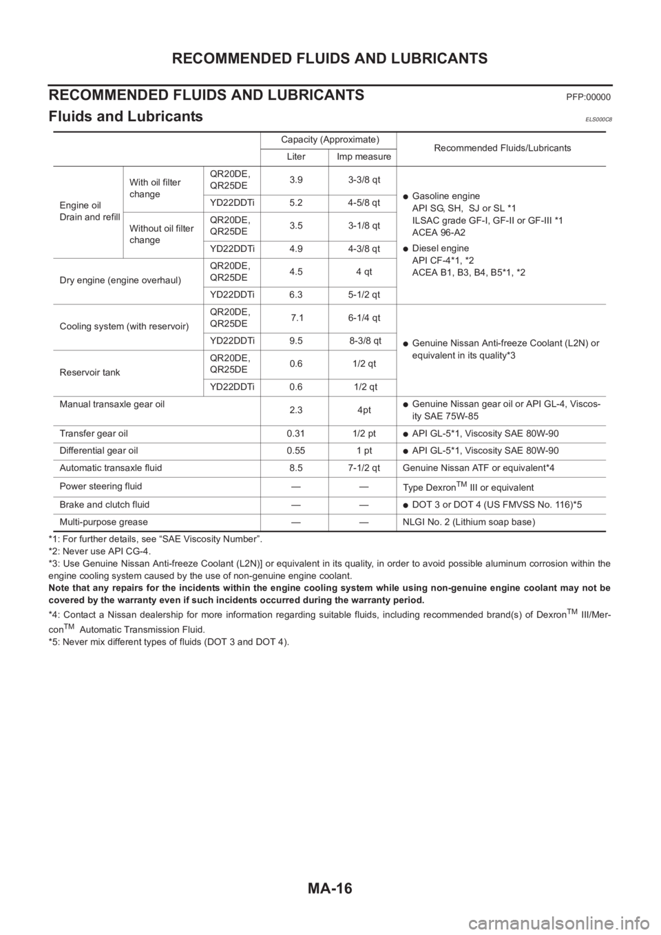
Fluids and LubricantsELS000C8
*1: For further details, see “SAE Viscosity Number”.
*2: Never use API CG-4.
*3: Use Genuine Nissan Anti-freeze Coolant (L2N)] or equivalent in its quality, in order to avoid possible aluminum corrosion within the
engine cooling system caused by the use of non-genuine engine coolant.
Note that any repairs for the incidents within the engine cooling system while using non-genuine engine coolant may not be
covered by the warranty even if such incidents occurred during the warranty period.
*4: Contact a Nissan dealership for more information regarding suitable fluids, including recommended brand(s) of Dexron
TM III/Mer-
conTM Automatic Transmission Fluid.
*5: Never mix different types of fluids (DOT 3 and DOT 4).Capacity (Approximate)
Recommended Fluids/Lubricants
Liter Imp measure
Engine oil
Drain and refillWith oil filter
changeQR20DE,
QR25DE3.9 3-3/8 qt
●Gasoline engine
API SG, SH, SJ or SL *1
ILSAC grade GF-I, GF-II or GF-III *1
ACEA 96-A2
●Diesel engine
API CF-4*1, *2
ACEA B1, B3, B4, B5*1, *2 YD22DDTi 5.2 4-5/8 qt
Without oil filter
changeQR20DE,
QR25DE3.5 3-1/8 qt
YD22DDTi 4.9 4-3/8 qt
Dry engine (engine overhaul)QR20DE,
QR25DE4.5 4 qt
YD22DDTi 6.3 5-1/2 qt
Cooling system (with reservoir)QR20DE,
QR25DE 7.1 6-1/4 qt
●Genuine Nissan Anti-freeze Coolant (L2N) or
equivalent in its quality*3 YD22DDTi 9.5 8-3/8 qt
Reservoir tankQR20DE,
QR25DE0.6 1/2 qt
YD22DDTi 0.6 1/2 qt
Manual transaxle gear oil
2.3 4pt
●Genuine Nissan gear oil or API GL-4, Viscos-
ity SAE 75W-85
Transfer gear oil 0.31 1/2 pt
●API GL-5*1, Viscosity SAE 80W-90
Differential gear oil 0.55 1 pt
●API GL-5*1, Viscosity SAE 80W-90
Automatic transaxle fluid 8.5 7-1/2 qt Genuine Nissan ATF or equivalent*4
Power steering fluid — —
Type Dexron
TM III or equivalent
Brake and clutch fluid — —
●DOT 3 or DOT 4 (US FMVSS No. 116)*5
Multi-purpose grease — — NLGI No. 2 (Lithium soap base)