manual transmission NISSAN X-TRAIL 2001 Service Repair Manual
[x] Cancel search | Manufacturer: NISSAN, Model Year: 2001, Model line: X-TRAIL, Model: NISSAN X-TRAIL 2001Pages: 3833, PDF Size: 39.49 MB
Page 1 of 3833
MODEL T30 SERIES
© 2002 NISSAN EUROPE S.A.S.
All rights reserved. No part of this Electronic Service Manual may be reproduced or stored in a retrieval system, or transmitted in any
form, or by any means, electronic, mechanical, photocopying, recording or otherwise, without the prior written permission of Nissan
Europe S.A.S., Paris, France.
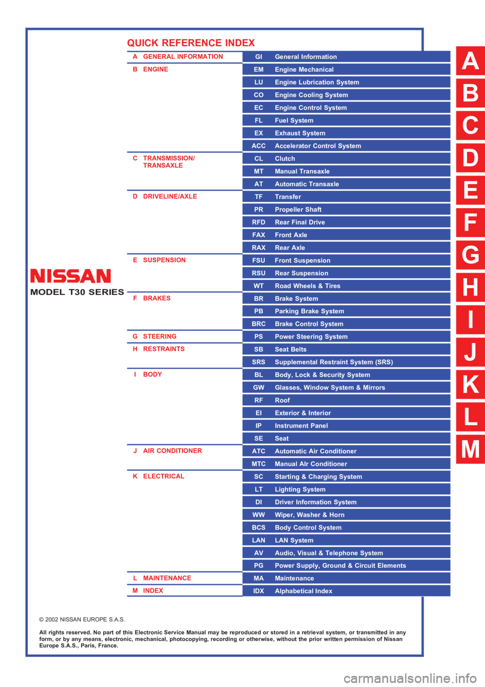
A GENERAL INFORMATION
B ENGINE
C TRANSMISSION/
TRANSAXLE
D DRIVELINE/AXLE
E SUSPENSION
F BRAKES
G STEERING
H RESTRAINTS
IBODY
J AIR CONDITIONER
K ELECTRICAL
L MAINTENANCE
M INDEXGI General Information
EM Engine Mechanical
LU Engine Lubrication System
CO Engine Cooling System
EC Engine Control System
FL Fuel System
EX Exhaust System
ACC Accelerator Control System
CL Clutch
MT Manual Transaxle
AT Automatic Transaxle
TF Transfer
PR Propeller Shaft
RFD Rear Final Drive
FAX Front Axle
RAX Rear Axle
FSU Front Suspension
RSU Rear Suspension
WT Road Wheels & Tires
BR Brake System
PB Parking Brake System
BRC Brake Control System
PS Power Steering System
SB Seat Belts
SRS Supplemental Restraint System (SRS)
BL Body, Lock & Security System
GW Glasses, Window System & Mirrors
RF Roof
EI Exterior & Interior
IP Instrument Panel
SE Seat
ATC Automatic Air Conditioner
MTC Manual AIr Conditioner
SC Starting & Charging System
LT Lighting System
DI Driver Information System
WW Wiper, Washer & Horn
BCS Body Control System
LAN LAN System
AV Audio, Visual & Telephone System
PG Power Supply, Ground & Circuit Elements
MA Maintenance
IDX Alphabetical Index
QUICK REFERENCE INDEX
A
B
C
D
E
F
G
H
I
J
K
L
M
Page 10 of 3833
GI-8
HOW TO USE THIS MANUAL
HOW TO USE THIS MANUAL
PFP:00008
Description EAS000FY
This volume explains “Removal, Disassembly, Installation, Inspection and Adjustment” and “Trouble Diag-
noses”.
Te r m sEAS000FZ
●The captions WARNING and CAUTION warn you of steps that must be followed to prevent personal
injury and/or damage to some part of the vehicle.
WARNING indicates the possibility of personal injury if instructions are not followed.
CAUTION indicates the possibility of component damage if instructions are not followed.
BOLD TYPED STATEMENTS except WARNING and CAUTION give you helpful information.
Standard value:Tolerance at inspection and adjustment.
Limit value:The maximum or minimum limit value that should not be exceeded at inspection and adjust-
ment.
UnitsEAS000G0
●The UNITS given in this manual are primarily expressed as the SI UNIT (International System of Unit),
and alternatively expressed in the metric system and in the yard/pound system.
“Example”
ContentsEAS000G1
●ALPHABETICAL INDEX is provided at the end of this manual so that you can rapidly find the item and
page you are searching for.
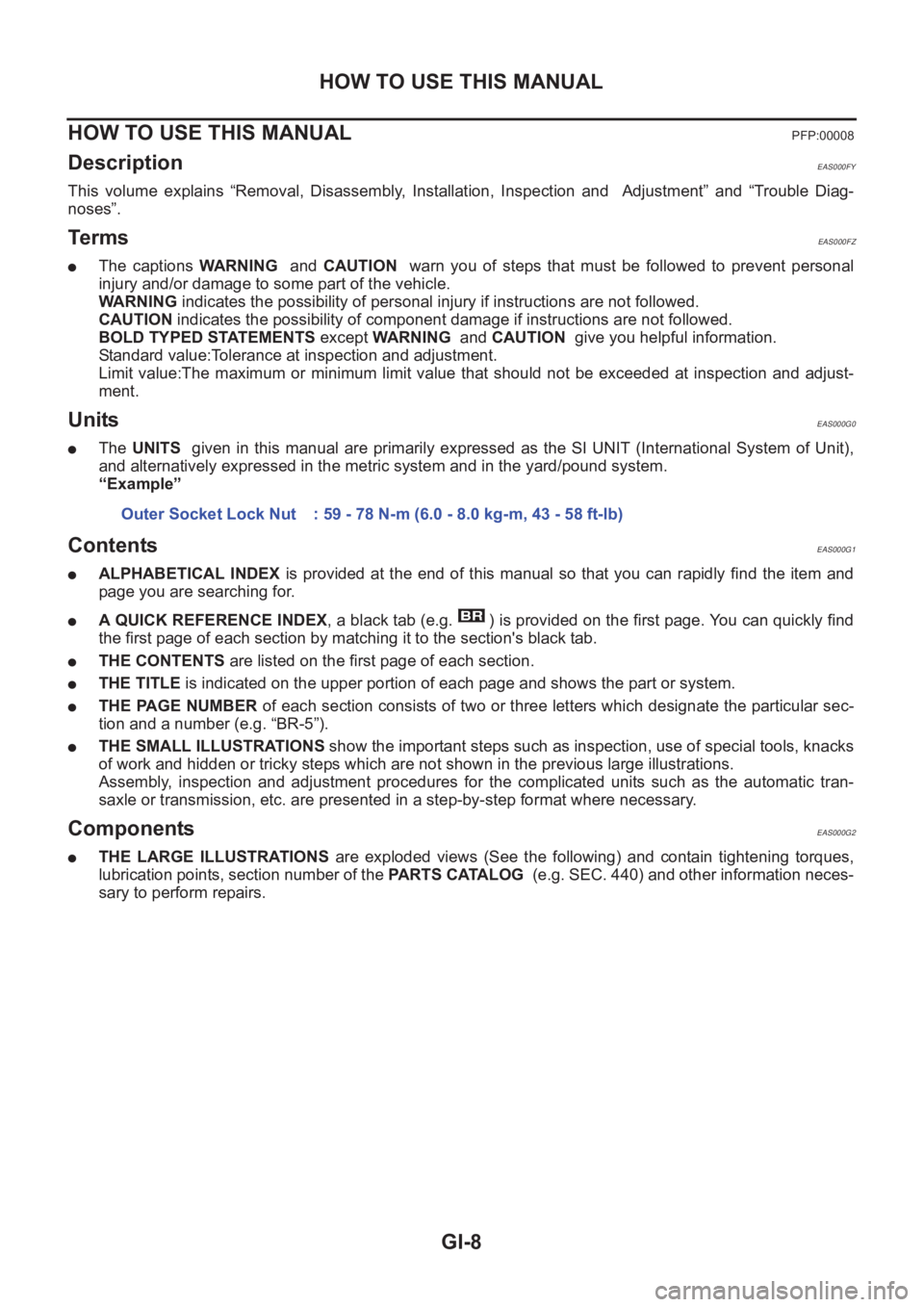
●A QUICK REFERENCE INDEX, a black tab (e.g. ) is provided on the first page. You can quickly find
the first page of each section by matching it to the section's black tab.
●THE CONTENTS are listed on the first page of each section.
●THE TITLE is indicated on the upper portion of each page and shows the part or system.
●THE PAGE NUMBER of each section consists of two or three letters which designate the particular sec-
tion and a number (e.g. “BR-5”).
●THE SMALL ILLUSTRATIONS show the important steps such as inspection, use of special tools, knacks
of work and hidden or tricky steps which are not shown in the previous large illustrations.
Assembly, inspection and adjustment procedures for the complicated units such as the automatic tran-
saxle or transmission, etc. are presented in a step-by-step format where necessary.
ComponentsEAS000G2
●THE LARGE ILLUSTRATIONS are exploded views (See the following) and contain tightening torques,
lubrication points, section number of the PARTS CATALOG (e.g. SEC. 440) and other information neces-
sary to perform repairs.Outer Socket Lock Nut : 59 - 78 N-m (6.0 - 8.0 kg-m, 43 - 58 ft-lb)
Page 24 of 3833
GI-22
HOW TO USE THIS MANUAL
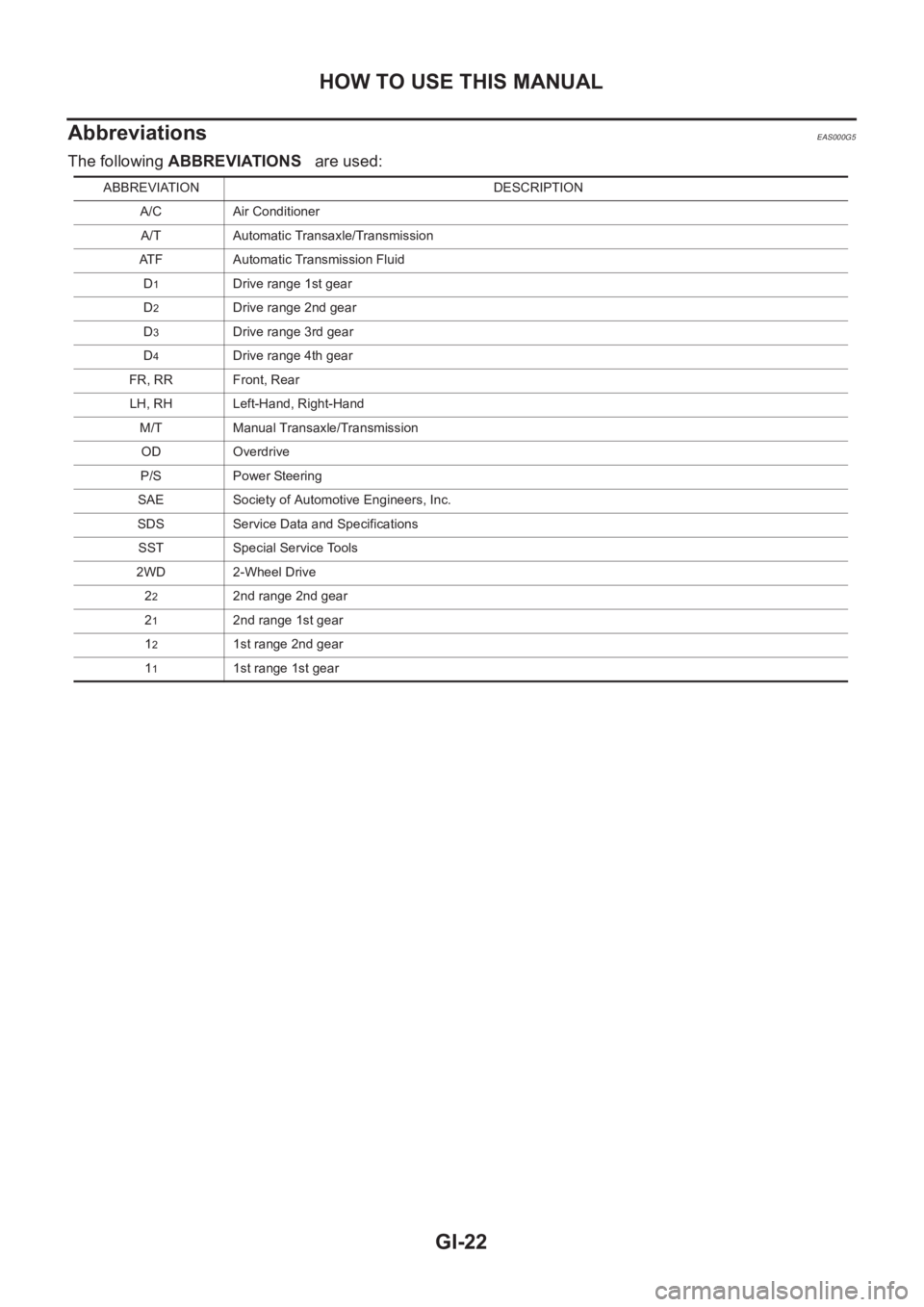
Abbreviations
EAS000G5
The following ABBREVIATIONS are used:
ABBREVIATION DESCRIPTION
A/C Air Conditioner
A/T Automatic Transaxle/Transmission
ATF Automatic Transmission Fluid
D
1Drive range 1st gear
D
2Drive range 2nd gear
D
3Drive range 3rd gear
D
4Drive range 4th gear
FR, RR Front, Rear
LH, RH Left-Hand, Right-Hand
M/T Manual Transaxle/Transmission
OD Overdrive
P/S Power Steering
SAE Society of Automotive Engineers, Inc.
SDS Service Data and Specifications
SST Special Service Tools
2WD 2-Wheel Drive
2
22nd range 2nd gear
2
12nd range 1st gear
1
21st range 2nd gear
1
11st range 1st gear
Page 25 of 3833
SERVICE INFORMATION FOR ELECTRICAL INCIDENT
GI-23
C
D
E
F
G
H
I
J
K
L
MB
GI
SERVICE INFORMATION FOR ELECTRICAL INCIDENTPFP:00000
How to Perform Efficient Diagnosis for an Electrical IncidentEAS000G6
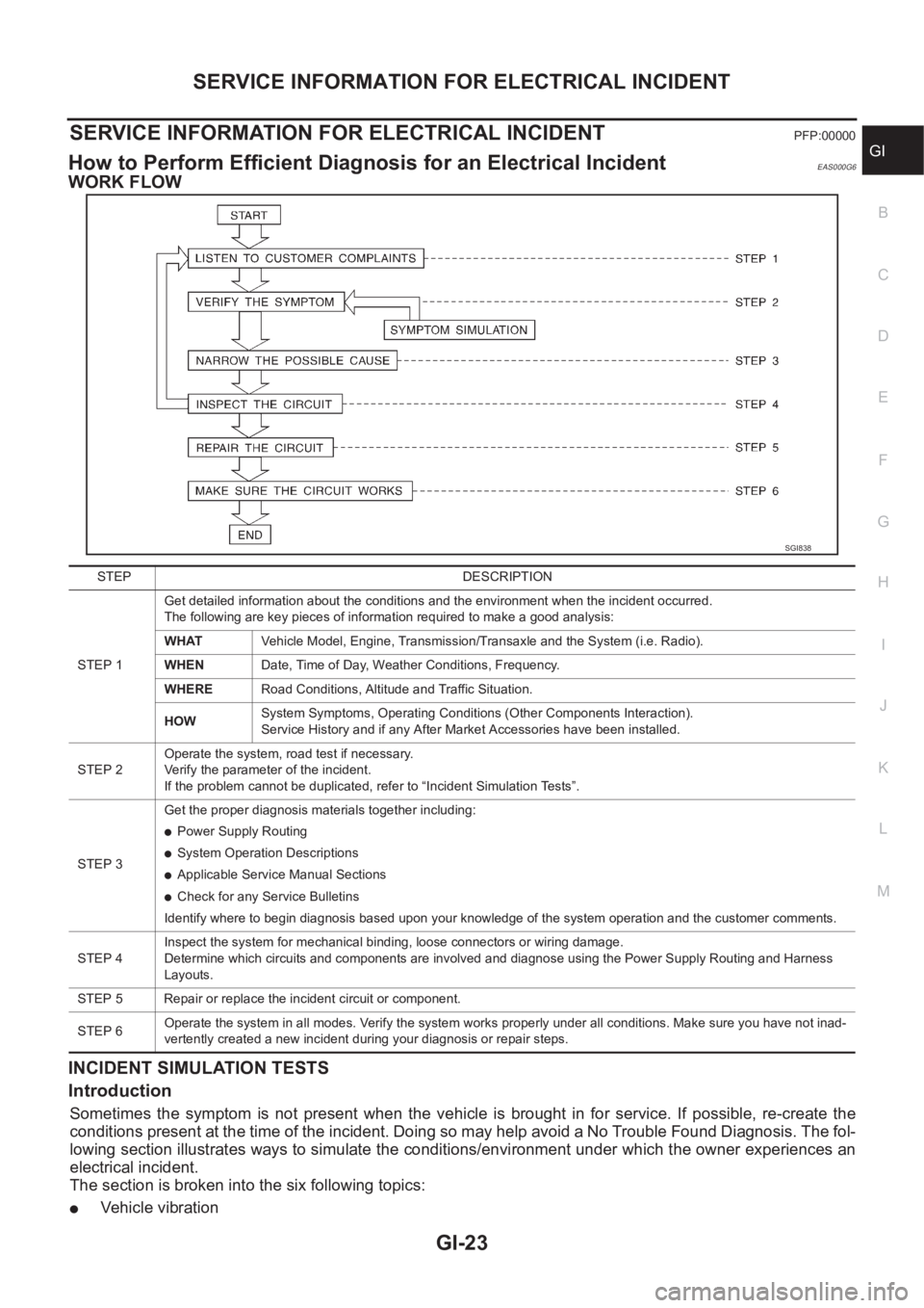
WORK FLOW
INCIDENT SIMULATION TESTS
Introduction
Sometimes the symptom is not present when the vehicle is brought in for service. If possible, re-create the
conditions present at the time of the incident. Doing so may help avoid a No Trouble Found Diagnosis. The fol-
lowing section illustrates ways to simulate the conditions/environment under which the owner experiences an
electrical incident.
The section is broken into the six following topics:
●Vehicle vibration
SGI838
STEP DESCRIPTION
STEP 1Get detailed information about the conditions and the environment when the incident occurred.
The following are key pieces of information required to make a good analysis:
WHATVehicle Model, Engine, Transmission/Transaxle and the System (i.e. Radio).
WHENDate, Time of Day, Weather Conditions, Frequency.
WHERERoad Conditions, Altitude and Traffic Situation.
HOWSystem Symptoms, Operating Conditions (Other Components Interaction).
Service History and if any After Market Accessories have been installed.
STEP 2Operate the system, road test if necessary.
Verify the parameter of the incident.
If the problem cannot be duplicated, refer to “Incident Simulation Tests”.
STEP 3Get the proper diagnosis materials together including:
●Power Supply Routing
●System Operation Descriptions
●Applicable Service Manual Sections
●Check for any Service Bulletins
Identify where to begin diagnosis based upon your knowledge of the system operation and the customer comments.
STEP 4Inspect the system for mechanical binding, loose connectors or wiring damage.
Determine which circuits and components are involved and diagnose using the Power Supply Routing and Harness
Layouts.
STEP 5 Repair or replace the incident circuit or component.
STEP 6Operate the system in all modes. Verify the system works properly under all conditions. Make sure you have not inad-
vertently created a new incident during your diagnosis or repair steps.
Page 40 of 3833
GI-38
TOW TRUCK TOWING
TOW TRUCK TOWING
PFP:00000
Tow Truck TowingEAS000FL
CAUTION:
●All applicable local laws regarding the towing operation must be obeyed.
●It is necessary to use proper towing equipment to avoid possible damage to the vehicle during
towing operation. Towing is in accordance with Towing Procedure Manual at dealer.
●Always attach safety chains before towing.
●When towing, make sure that the transmission, steering system and power train are in good order.
If any unit is damaged, dollies must be used.
●Never tow an automatic transmission model from the rear (that is backward) with four wheels on
the ground. This may cause serious and expensive damage to the transmission.
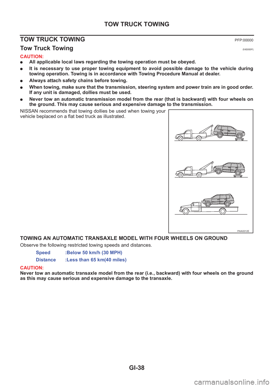
NISSAN recommends that towing dollies be used when towing your
vehicle beplaced on a flat bed truck as illustrated.
TOWING AN AUTOMATIC TRANSAXLE MODEL WITH FOUR WHEELS ON GROUND
Observe the following restricted towing speeds and distances.
CAUTION:
Never tow an automatic transaxle model from the rear (i.e., backward) with four wheels on the ground
as this may cause serious and expensive damage to the transaxle.
PAIA0012E
Speed :Below 50 km/h (30 MPH)
Distance :Less than 65 km(40 miles)
Page 375 of 3833
![NISSAN X-TRAIL 2001 Service Repair Manual PRECAUTIONS
EC-25
[QR25(WITH EURO-OBD)]
C
D
E
F
G
H
I
J
K
L
MA
EC
PRECAUTIONSPFP:00001
Precautions for Supplemental Restraint System (SRS) “AIR BAG” and “SEAT
BELT PRE-TENSIONER”
EBS00NBQ
The NISSAN X-TRAIL 2001 Service Repair Manual PRECAUTIONS
EC-25
[QR25(WITH EURO-OBD)]
C
D
E
F
G
H
I
J
K
L
MA
EC
PRECAUTIONSPFP:00001
Precautions for Supplemental Restraint System (SRS) “AIR BAG” and “SEAT
BELT PRE-TENSIONER”
EBS00NBQ
The](/img/5/57405/w960_57405-374.png)
PRECAUTIONS
EC-25
[QR25(WITH EURO-OBD)]
C
D
E
F
G
H
I
J
K
L
MA
EC
PRECAUTIONSPFP:00001
Precautions for Supplemental Restraint System (SRS) “AIR BAG” and “SEAT
BELT PRE-TENSIONER”
EBS00NBQ
The Supplemental Restraint System such as “AIR BAG” and “SEAT BELT PRE-TENSIONER”, used along
with a front seat belt, helps to reduce the risk or severity of injury to the driver and front passenger for certain
types of collision. Information necessary to service the system safely is included in the SRS and SB section of
this Service Manual.
WARNING:
●To avoid rendering the SRS inoperative, which could increase the risk of personal injury or death
in the event of a collision which would result in air bag inflation, all maintenance must be per-
formed by an authorized NISSAN/INFINITI dealer.
●Improper maintenance, including incorrect removal and installation of the SRS, can lead to per-
sonal injury caused by unintentional activation of the system. For removal of Spiral Cable and Air
Bag Module, see the SRS section.
●Do not use electrical test equipment on any circuit related to the SRS unless instructed to in this
Service Manual. SRS wiring harnesses can be identified by yellow and/or orange harness connec-
tors.
On Board Diagnostic (OBD) System of Engine and A/TEBS00M04
The ECM has an on board diagnostic system. It will light up the malfunction indicator (MI) to warn the driver of
a malfunction causing emission deterioration.
CAUTION:
●Be sure to turn the ignition switch OFF and disconnect the negative battery terminal before any
repair or inspection work. The open/short circuit of related switches, sensors, solenoid valves,
etc. will cause the MI to light up.
●Be sure to connect and lock the connectors securely after work. A loose (unlocked) connector will
cause the MI to light up due to the open circuit. (Be sure the connector is free from water, grease,
dirt, bent terminals, etc.)
●Certain systems and components, especially those related to OBD, may use a new style slide-
locking type harness connector. For description and how to disconnect, refer to PG-68, "
HAR-
NESS CONNECTOR" .
●Be sure to route and secure the harnesses properly after work. The interference of the harness
with a bracket, etc. may cause the MI to light up due to the short circuit.
●Be sure to connect rubber tubes properly after work. A misconnected or disconnected rubber tube
may cause the MI to light up due to the malfunction of the fuel injection system, etc.
●Be sure to erase the unnecessary malfunction information (repairs completed) from the ECM and
TCM (Transmission control module) before returning the vehicle to the customer.
PrecautionEBS00M05
●Always use a 12 volt battery as power source.
●Do not attempt to disconnect battery cables while engine is
running.
●Before connecting or disconnecting the ECM harness con-
nector, turn ignition switch OFF and disconnect negative
battery terminal. Failure to do so may damage the ECM
because battery voltage is applied to ECM even if ignition
switch is turned off.
●Before removing parts, turn ignition switch OFF and then
disconnect battery ground cable.
SEF289H
Page 785 of 3833
![NISSAN X-TRAIL 2001 Service Repair Manual PRECAUTIONS
EC-435
[QR25(WITHOUT EURO-OBD)]
C
D
E
F
G
H
I
J
K
L
MA
EC
PRECAUTIONSPFP:00001
Precautions for Supplemental Restraint System (SRS) “AIR BAG” and “SEAT
BELT PRE-TENSIONER”
EBS00NDL NISSAN X-TRAIL 2001 Service Repair Manual PRECAUTIONS
EC-435
[QR25(WITHOUT EURO-OBD)]
C
D
E
F
G
H
I
J
K
L
MA
EC
PRECAUTIONSPFP:00001
Precautions for Supplemental Restraint System (SRS) “AIR BAG” and “SEAT
BELT PRE-TENSIONER”
EBS00NDL](/img/5/57405/w960_57405-784.png)
PRECAUTIONS
EC-435
[QR25(WITHOUT EURO-OBD)]
C
D
E
F
G
H
I
J
K
L
MA
EC
PRECAUTIONSPFP:00001
Precautions for Supplemental Restraint System (SRS) “AIR BAG” and “SEAT
BELT PRE-TENSIONER”
EBS00NDL
The Supplemental Restraint System such as “AIR BAG” and “SEAT BELT PRE-TENSIONER”, used along
with a front seat belt, helps to reduce the risk or severity of injury to the driver and front passenger for certain
types of collision. Information necessary to service the system safely is included in the SRS and SB section of
this Service Manual.
WARNING:
●To avoid rendering the SRS inoperative, which could increase the risk of personal injury or death
in the event of a collision which would result in air bag inflation, all maintenance must be per-
formed by an authorized NISSAN/INFINITI dealer.
●Improper maintenance, including incorrect removal and installation of the SRS, can lead to per-
sonal injury caused by unintentional activation of the system. For removal of Spiral Cable and Air
Bag Module, see the SRS section.
●Do not use electrical test equipment on any circuit related to the SRS unless instructed to in this
Service Manual. SRS wiring harnesses can be identified by yellow and/or orange harness connec-
tors.
On Board Diagnostic (OBD) System of Engine and A/TEBS00NDM
The ECM has an on board diagnostic system. It will light up the malfunction indicator (MI) to warn the driver of
a malfunction causing emission deterioration.
CAUTION:
●Be sure to turn the ignition switch OFF and disconnect the negative battery terminal before any
repair or inspection work. The open/short circuit of related switches, sensors, solenoid valves,
etc. will cause the MI to light up.
●Be sure to connect and lock the connectors securely after work. A loose (unlocked) connector will
cause the MI to light up due to the open circuit. (Be sure the connector is free from water, grease,
dirt, bent terminals, etc.)
●Certain systems and components, especially those related to OBD, may use a new style slide-
locking type harness connector. For description and how to disconnect, refer to PG-68, "
HAR-
NESS CONNECTOR" .
●Be sure to route and secure the harnesses properly after work. The interference of the harness
with a bracket, etc. may cause the MI to light up due to the short circuit.
●Be sure to connect rubber tubes properly after work. A misconnected or disconnected rubber tube
may cause the MI to light up due to the malfunction of the fuel injection system, etc.
●Be sure to erase the unnecessary malfunction information (repairs completed) from the ECM and
TCM (Transmission control module) before returning the vehicle to the customer.
PrecautionEBS00NDN
●Always use a 12 volt battery as power source.
●Do not attempt to disconnect battery cables while engine is
running.
●Before connecting or disconnecting the ECM harness con-
nector, turn ignition switch OFF and disconnect negative
battery terminal. Failure to do so may damage the ECM
because battery voltage is applied to ECM even if ignition
switch is turned off.
●Before removing parts, turn ignition switch OFF and then
disconnect battery ground cable.
SEF289H
Page 1107 of 3833
![NISSAN X-TRAIL 2001 Service Repair Manual PRECAUTIONS
EC-757
[QR20(WITH EURO-OBD)]
C
D
E
F
G
H
I
J
K
L
MA
EC
PRECAUTIONSPFP:00001
Precautions for Supplemental Restraint System (SRS) “AIR BAG” and “SEAT
BELT PRE-TENSIONER”
EBS00NBR
Th NISSAN X-TRAIL 2001 Service Repair Manual PRECAUTIONS
EC-757
[QR20(WITH EURO-OBD)]
C
D
E
F
G
H
I
J
K
L
MA
EC
PRECAUTIONSPFP:00001
Precautions for Supplemental Restraint System (SRS) “AIR BAG” and “SEAT
BELT PRE-TENSIONER”
EBS00NBR
Th](/img/5/57405/w960_57405-1106.png)
PRECAUTIONS
EC-757
[QR20(WITH EURO-OBD)]
C
D
E
F
G
H
I
J
K
L
MA
EC
PRECAUTIONSPFP:00001
Precautions for Supplemental Restraint System (SRS) “AIR BAG” and “SEAT
BELT PRE-TENSIONER”
EBS00NBR
The Supplemental Restraint System such as “AIR BAG” and “SEAT BELT PRE-TENSIONER”, used along
with a front seat belt, helps to reduce the risk or severity of injury to the driver and front passenger for certain
types of collision. Information necessary to service the system safely is included in the SRS and SB section of
this Service Manual.
WARNING:
●To avoid rendering the SRS inoperative, which could increase the risk of personal injury or death
in the event of a collision which would result in air bag inflation, all maintenance must be per-
formed by an authorized NISSAN/INFINITI dealer.
●Improper maintenance, including incorrect removal and installation of the SRS, can lead to per-
sonal injury caused by unintentional activation of the system. For removal of Spiral Cable and Air
Bag Module, see the SRS section.
●Do not use electrical test equipment on any circuit related to the SRS unless instructed to in this
Service Manual. SRS wiring harnesses can be identified by yellow and/or orange harness connec-
tors.
On Board Diagnostic (OBD) System of Engine and A/TEBS00MS3
The ECM has an on board diagnostic system. It will light up the malfunction indicator (MI) to warn the driver of
a malfunction causing emission deterioration.
CAUTION:
●Be sure to turn the ignition switch OFF and disconnect the negative battery terminal before any
repair or inspection work. The open/short circuit of related switches, sensors, solenoid valves,
etc. will cause the MI to light up.
●Be sure to connect and lock the connectors securely after work. A loose (unlocked) connector will
cause the MI to light up due to the open circuit. (Be sure the connector is free from water, grease,
dirt, bent terminals, etc.)
●Certain systems and components, especially those related to OBD, may use a new style slide-
locking type harness connector. For description and how to disconnect, refer to PG-68, "
HAR-
NESS CONNECTOR" .
●Be sure to route and secure the harnesses properly after work. The interference of the harness
with a bracket, etc. may cause the MI to light up due to the short circuit.
●Be sure to connect rubber tubes properly after work. A misconnected or disconnected rubber tube
may cause the MI to light up due to the malfunction of the fuel injection system, etc.
●Be sure to erase the unnecessary malfunction information (repairs completed) from the ECM and
TCM (Transmission control module) before returning the vehicle to the customer.
PrecautionEBS00MS4
●Always use a 12 volt battery as power source.
●Do not attempt to disconnect battery cables while engine is
running.
●Before connecting or disconnecting the ECM harness con-
nector, turn ignition switch OFF and disconnect negative
battery terminal. Failure to do so may damage the ECM
because battery voltage is applied to ECM even if ignition
switch is turned off.
●Before removing parts, turn ignition switch OFF and then
disconnect battery ground cable.
SEF289H
Page 1471 of 3833
![NISSAN X-TRAIL 2001 Service Repair Manual PRECAUTIONS
EC-1121
[QR20(WITHOUT EURO-OBD)]
C
D
E
F
G
H
I
J
K
L
MA
EC
PRECAUTIONSPFP:00001
Precautions for Supplemental Restraint System (SRS) “AIR BAG” and “SEAT
BELT PRE-TENSIONER”
EBS00NB NISSAN X-TRAIL 2001 Service Repair Manual PRECAUTIONS
EC-1121
[QR20(WITHOUT EURO-OBD)]
C
D
E
F
G
H
I
J
K
L
MA
EC
PRECAUTIONSPFP:00001
Precautions for Supplemental Restraint System (SRS) “AIR BAG” and “SEAT
BELT PRE-TENSIONER”
EBS00NB](/img/5/57405/w960_57405-1470.png)
PRECAUTIONS
EC-1121
[QR20(WITHOUT EURO-OBD)]
C
D
E
F
G
H
I
J
K
L
MA
EC
PRECAUTIONSPFP:00001
Precautions for Supplemental Restraint System (SRS) “AIR BAG” and “SEAT
BELT PRE-TENSIONER”
EBS00NBS
The Supplemental Restraint System such as “AIR BAG” and “SEAT BELT PRE-TENSIONER”, used along
with a front seat belt, helps to reduce the risk or severity of injury to the driver and front passenger for certain
types of collision. Information necessary to service the system safely is included in the SRS and SB section of
this Service Manual.
WARNING:
●To avoid rendering the SRS inoperative, which could increase the risk of personal injury or death
in the event of a collision which would result in air bag inflation, all maintenance must be per-
formed by an authorized NISSAN/INFINITI dealer.
●Improper maintenance, including incorrect removal and installation of the SRS, can lead to per-
sonal injury caused by unintentional activation of the system. For removal of Spiral Cable and Air
Bag Module, see the SRS section.
●Do not use electrical test equipment on any circuit related to the SRS unless instructed to in this
Service Manual. SRS wiring harnesses can be identified by yellow and/or orange harness connec-
tors.
On Board Diagnostic (OBD) System of Engine and A/TEBS00N39
The ECM has an on board diagnostic system. It will light up the malfunction indicator (MI) to warn the driver of
a malfunction causing emission deterioration.
CAUTION:
●Be sure to turn the ignition switch OFF and disconnect the negative battery terminal before any
repair or inspection work. The open/short circuit of related switches, sensors, solenoid valves,
etc. will cause the MI to light up.
●Be sure to connect and lock the connectors securely after work. A loose (unlocked) connector will
cause the MI to light up due to the open circuit. (Be sure the connector is free from water, grease,
dirt, bent terminals, etc.)
●Certain systems and components, especially those related to OBD, may use a new style slide-
locking type harness connector. For description and how to disconnect, refer to PG-68, "
HAR-
NESS CONNECTOR" .
●Be sure to route and secure the harnesses properly after work. The interference of the harness
with a bracket, etc. may cause the MI to light up due to the short circuit.
●Be sure to connect rubber tubes properly after work. A misconnected or disconnected rubber tube
may cause the MI to light up due to the malfunction of the fuel injection system, etc.
●Be sure to erase the unnecessary malfunction information (repairs completed) from the ECM and
TCM (Transmission control module) before returning the vehicle to the customer.
PrecautionEBS00N3A
●Always use a 12 volt battery as power source.
●Do not attempt to disconnect battery cables while engine is
running.
●Before connecting or disconnecting the ECM harness con-
nector, turn ignition switch OFF and disconnect negative
battery terminal. Failure to do so may damage the ECM
because battery voltage is applied to ECM even if ignition
switch is turned off.
●Before removing parts, turn ignition switch OFF and then
disconnect battery ground cable.
SEF289H
Page 1977 of 3833
MT-1
MANUAL TRANSAXLE
C TRANSMISSION/TRANSAXLE
CONTENTS
D
E
F
G
H
I
J
K
L
M
SECTION
A
B
MT
MANUAL TRANSAXLE
PRECAUTIONS .......................................................... 3
Caution ..................................................................... 3
PREPARATION ........................................................... 4
Special Service Tools ............................................... 4
Commercial Service Tools ........................................ 6
NOISE, VIBRATION, AND HARSHNESS (NVH)
TROUBLESHOOTING ................................................ 7
NVH Troubleshooting Chart ..................................... 7
MANUAL TRANSAXLE ......................................... 7
DESCRIPTION ............................................................ 8
Cross-Sectional View ............................................... 8
DOUBLE-CONE SYNCHRONIZER ...................... 9
REVERSE GEAR NOISE PREVENTION FUNC-
TION (SYNCHRONIZING METHOD) ................... 9
M/T OIL ..................................................................... 10
Changing M/T Oil ................................................... 10
DRAINING ........................................................... 10
FILLING ............................................................... 10
Checking M/T Oil .................................................... 10
OIL LEAKAGE AND OIL LEVEL ......................... 10
SIDE OIL SEAL .........................................................11
Removal and Installation ......................................... 11
REMOVAL ............................................................ 11
INSTALLATION .................................................... 11
POSITION SWITCH .................................................. 12
Checking ................................................................ 12
BACK-UP LAMP SWITCH .................................. 12
PARK/NEUTRAL POSITION SWITCH ............... 12
CONTROL LINKAGE ............................................... 13
Removal and Installation of Control Device and
Cable ...................................................................... 13
AIR BREATHER HOSE ............................................ 14
Removal and Installation ........................................ 14
TRANSAXLE ASSEMBLY ........................................ 15
Removal and Installation ........................................ 15
REMOVAL ........................................................... 15
INSTALLATION ................................................... 16
Component Parts (RS5F51A) ................................ 17CASE AND HOUSING COMPONENTS .............. 17
GEAR COMPONENTS ....................................... 18
SHIFT CONTROL COMPONENTS ..................... 20
FINAL DRIVE COMPONENTS ........................... 21
Component Parts (RS6F51A) ................................. 22
CASE AND HOUSING COMPONENTS .............. 22
GEAR COMPONENTS ....................................... 23
SHIFT CONTROL COMPONENTS ..................... 25
FINAL DRIVE COMPONENTS ........................... 26
Disassembly and Assembly (RS5F51A) ................. 26
DISASSEMBLY ................................................... 26
ASSEMBLY ......................................................... 30
Disassembly and Assembly (RS6F51A) ................. 35
DISASSEMBLY ................................................... 35
ASSEMBLY ......................................................... 39
Adjustment (RS5F51A) ........................................... 45
INPUT SHAFT END PLAY .................................. 45
MAINSHAFT END PLAY ..................................... 46
DIFFERENTIAL SIDE BEARING PRELOAD ...... 47
REVERSE IDLER GEAR END PLAY .................. 48
Adjustment (RS6F51A) ........................................... 49
INPUT SHAFT END PLAY .................................. 49
MAINSHAFT END PLAY ..................................... 50
DIFFERENTIAL SIDE BEARING PRELOAD ...... 51
REVERSE IDLER GEAR END PLAY .................. 52
INPUT SHAFT AND GEARS .................................... 54
Assembly and Disassembly (RS5F51A) ................. 54
DISASSEMBLY ................................................... 54
INSPECTION AFTER DISASSEMBLY ................ 55
ASSEMBLY ......................................................... 57
Assembly and Disassembly (RS6F51A) ................. 61
DISASSEMBLY ................................................... 61
INSPECTION AFTER DISASSEMBLY ................ 62
ASSEMBLY ......................................................... 64
MAINSHAFT AND GEARS ....................................... 68
Assembly and Disassembly (RS5F51A) ................. 68
DISASSEMBLY ................................................... 68
INSPECTION AFTER DISASSEMBLY ................ 69