oil capacity NISSAN X-TRAIL 2001 Service User Guide
[x] Cancel search | Manufacturer: NISSAN, Model Year: 2001, Model line: X-TRAIL, Model: NISSAN X-TRAIL 2001Pages: 3833, PDF Size: 39.49 MB
Page 2705 of 3833
SERVICE DATA AND SPECIFICATIONS (SDS)
RFD-29
C
E
F
G
H
I
J
K
L
MA
B
RFD
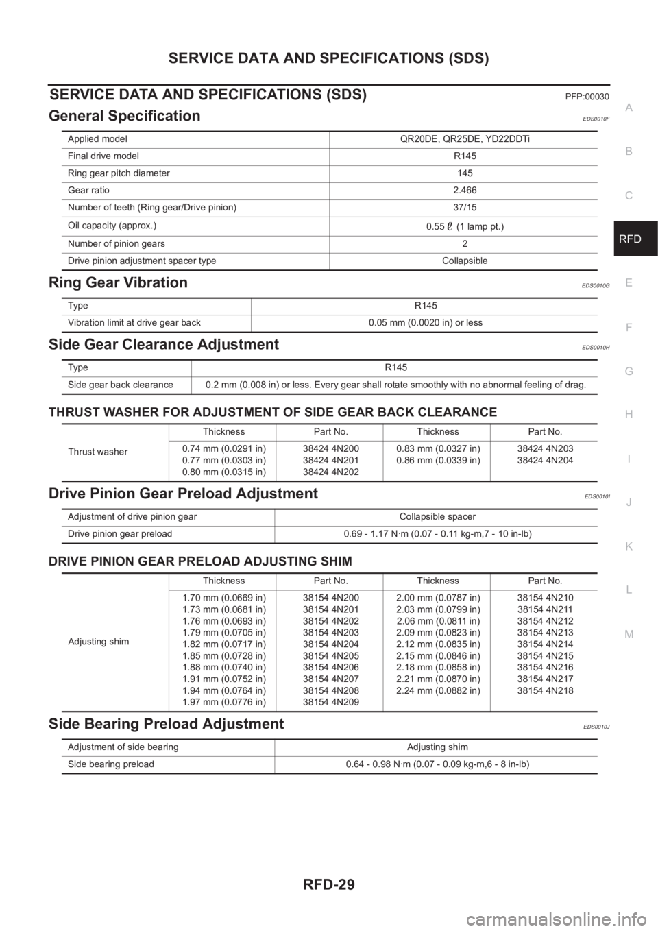
SERVICE DATA AND SPECIFICATIONS (SDS)PFP:00030
General SpecificationEDS0010F
Ring Gear VibrationEDS0010G
Side Gear Clearance AdjustmentEDS0010H
THRUST WASHER FOR ADJUSTMENT OF SIDE GEAR BACK CLEARANCE
Drive Pinion Gear Preload AdjustmentEDS0010I
DRIVE PINION GEAR PRELOAD ADJUSTING SHIM
Side Bearing Preload AdjustmentEDS0010J
Applied model QR20DE, QR25DE, YD22DDTi
Final drive modelR145
Ring gear pitch diameter 145
Gear ratio2.466
Number of teeth (Ring gear/Drive pinion) 37/15
Oil capacity (approx.)
0.55 (1 lamp pt.)
Number of pinion gears2
Drive pinion adjustment spacer type Collapsible
Ty p eR145
Vibration limit at drive gear back 0.05 mm (0.0020 in) or less
Ty p e R 1 4 5
Side gear back clearance 0.2 mm (0.008 in) or less. Every gear shall rotate smoothly with no abnormal feeling of drag.
Thrust washerThickness Part No. Thickness Part No.
0.74 mm (0.0291 in)
0.77 mm (0.0303 in)
0.80 mm (0.0315 in)38424 4N200
38424 4N201
38424 4N2020.83 mm (0.0327 in)
0.86 mm (0.0339 in)38424 4N203
38424 4N204
Adjustment of drive pinion gear Collapsible spacer
Drive pinion gear preload 0.69 - 1.17 N·m (0.07 - 0.11 kg-m,7 - 10 in-lb)
Adjusting shimThickness Part No. Thickness Part No.
1.70 mm (0.0669 in)
1.73 mm (0.0681 in)
1.76 mm (0.0693 in)
1.79 mm (0.0705 in)
1.82 mm (0.0717 in)
1.85 mm (0.0728 in)
1.88 mm (0.0740 in)
1.91 mm (0.0752 in)
1.94 mm (0.0764 in)
1.97 mm (0.0776 in)38154 4N200
38154 4N201
38154 4N202
38154 4N203
38154 4N204
38154 4N205
38154 4N206
38154 4N207
38154 4N208
38154 4N2092.00 mm (0.0787 in)
2.03 mm (0.0799 in)
2.06 mm (0.0811 in)
2.09 mm (0.0823 in)
2.12 mm (0.0835 in)
2.15 mm (0.0846 in)
2.18 mm (0.0858 in)
2.21 mm (0.0870 in)
2.24 mm (0.0882 in)38154 4N210
38154 4N211
38154 4N212
38154 4N213
38154 4N214
38154 4N215
38154 4N216
38154 4N217
38154 4N218
Adjustment of side bearing Adjusting shim
Side bearing preload 0.64 - 0.98 N·m (0.07 - 0.09 kg-m,6 - 8 in-lb)
Page 2947 of 3833

SERVICE DATA AND SPECIFICATIONS (SDS)
PS-37
C
D
E
F
H
I
J
K
L
MA
B
PS
Steering GearEGS0004T
Oil PumpEGS0004U
Steering FluidEGS0004V
Steering gear model PR24AD
Rack neutral position,
dimension (L)66.5 mm (2.618 in)
Retainer adjustmentAdjusting screw lock nut tightening torque 39 - 59 N·m (4.0 - 6.0 kg-m, 29 - 43 ft-lb)
Primary Adjusting screw tightening torque 4.9 - 5.9 N·m (0.5 - 0.6 kg-m, 44 - 52 in-lb)
Re-tightening torque after tightened 4.9 - 5.9 N·m (0.5 - 0.6 kg-m, 44 - 52 in-lb)
Loosen the adjusting screws. 60 - 80°
Rack sliding torque:Range within ±11.5 mm from
neutral position
(Power ON)Area average value1.67 - 2.25 N·m (0.17 - 0.22 kg-m, 1.3 - 1.6
ft-lb)
Allowable variation 0.98 N·m (0.10 kg-m, 1 ft-lb) or less
Whole area (at power OFF)Peak value 2.94 N· m (0.30 kg-m, 2 ft-lb) or less
Allowable variation 1.47 N ·m (0.15 kg-m, 1 ft-lb) or less
SGIA0463E
Oil pump relief hydraulic pressure
8,140 - 8,728 (81.4 - 87.3 bar, 83 - 89 kg/cm2 , 1,180 - 1,266 psi)
Fluid capacity
Approx. 1.0 (7/8 lmp qt)
Page 3293 of 3833

PREPARATION
ATC-17
C
D
E
F
G
H
I
K
L
MA
B
AT C
(J-41459)
HFC-134a (R-134a) Dye injector
Use with J-41447, 1/4 ounce
bottleFor injecting 1/4 ounce of fluorescent
leak detection dye into A/C system.
(J-43872)
Refrigerant dye cleanerFor cleaning dye spills.
Manifold gauge set (with hoses
and couplers)
Identification:
●The gauge face indicates HFC-134a
(R-134a).
Fitting size: Thread size
●1/2″ -16 ACME
Service hoses
●High side hose
●Low side hose
●Utility hose
Hose color:
●Low hose: Blue with black stripe
●High hose: Red with black stripe
●Utility hose: Yellow with black stripe
or green with black stripe
Hose fitting to gauge:
●1/2″ -16 ACME
Service couplers
●High side coupler
●Low side coupler
Hose fitting to service hose:
●M14 x 1.5 fitting is optional or
permanently attached.
Refrigerant weight scaleFor measuring of refrigerant
Fitting size: Thread size
●1/2″ -16 ACME
Vacuum pump
(Including the isolator valve)
Capacity:
●Air displacement:4 CFM
●Micron rating:20 microns
●Oil capacity:482 g (17 oz)
Fitting size: Thread size
●1/2″ -16 ACME Tool number
Tool nameDescription
SHA440F
SHA441F
RJIA0196E
S-NT201
S-NT202
S-NT200
S-NT203
Page 3426 of 3833
ATC-150
SERVICE DATA AND SPECIFICATIONS (SDS)
SERVICE DATA AND SPECIFICATIONS (SDS)
PFP:00030
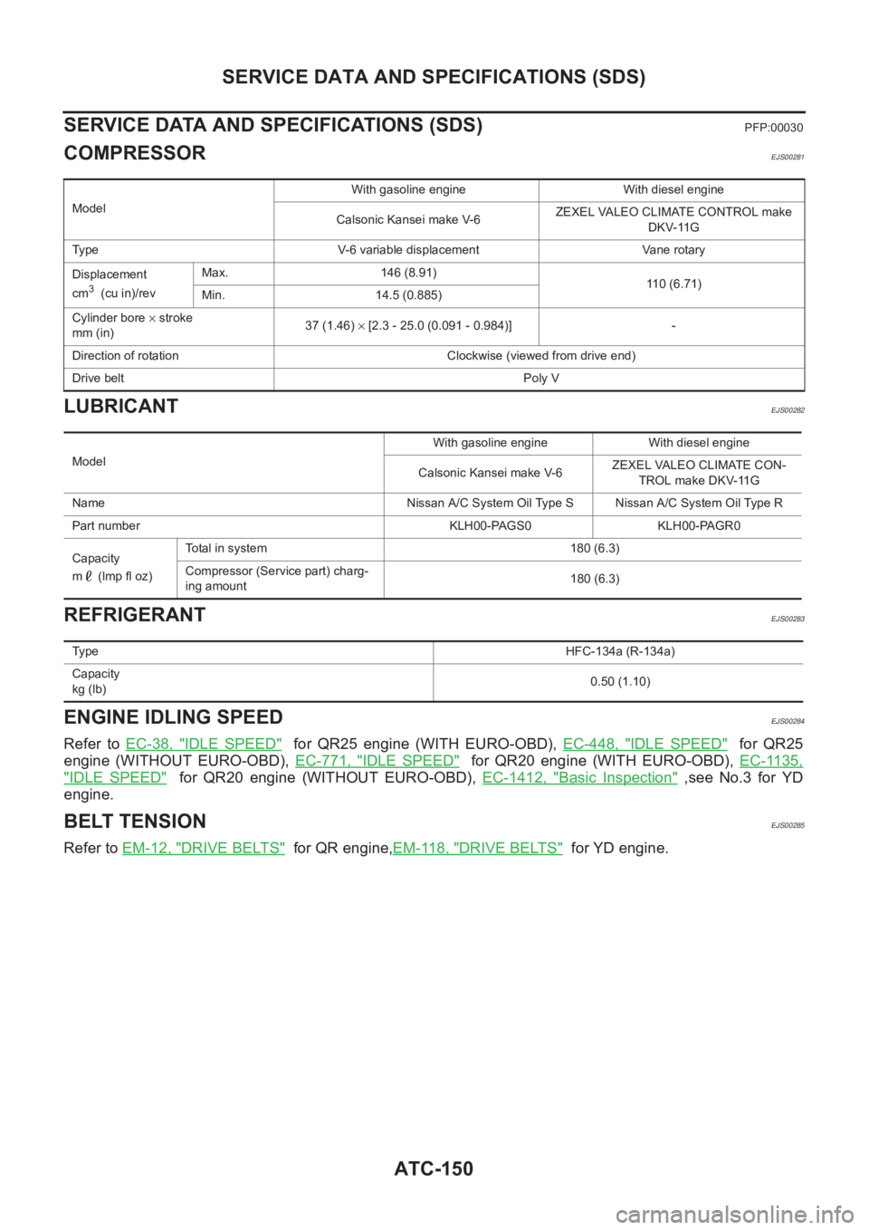
COMPRESSOREJS00281
LUBRICANTEJS00282
REFRIGERANTEJS00283
ENGINE IDLING SPEEDEJS00284
Refer to EC-38, "IDLE SPEED" for QR25 engine (WITH EURO-OBD), EC-448, "IDLE SPEED" for QR25
engine (WITHOUT EURO-OBD), EC-771, "
IDLE SPEED" for QR20 engine (WITH EURO-OBD), EC-1135,
"IDLE SPEED" for QR20 engine (WITHOUT EURO-OBD), EC-1412, "Basic Inspection" ,see No.3 for YD
engine.
BELT TENSIONEJS00285
Refer to EM-12, "DRIVE BELTS" for QR engine,EM-118, "DRIVE BELTS" for YD engine.
ModelWith gasoline engine With diesel engine
Calsonic Kansei make V-6ZEXEL VALEO CLIMATE CONTROL make
DKV-11G
Type V-6 variable displacement Vane rotary
Displacement
cm
3 (cu in)/revMax. 146 (8.91)
110 (6.71)
Min. 14.5 (0.885)
Cylinder bore × stroke
mm (in)37 (1.46) × [2.3 - 25.0 (0.091 - 0.984)] -
Direction of rotation Clockwise (viewed from drive end)
Drive beltPoly V
ModelWith gasoline engine With diesel engine
Calsonic Kansei make V-6ZEXEL VALEO CLIMATE CON-
TROL make DKV-11G
Name Nissan A/C System Oil Type S Nissan A/C System Oil Type R
Part number KLH00-PAGS0 KLH00-PAGR0
Capacity
m (lmp fl oz)Total in system 180 (6.3)
Compressor (Service part) charg-
ing amount180 (6.3)
Ty p eHFC-134a (R-134a)
Capacity
kg (lb)0.50 (1.10)
Page 3489 of 3833
SERVICE DATA AND SPECIFICATIONS (SDS)
SC-33
C
D
E
F
G
H
I
J
L
MA
B
SC
SERVICE DATA AND SPECIFICATIONS (SDS)PFP:00030
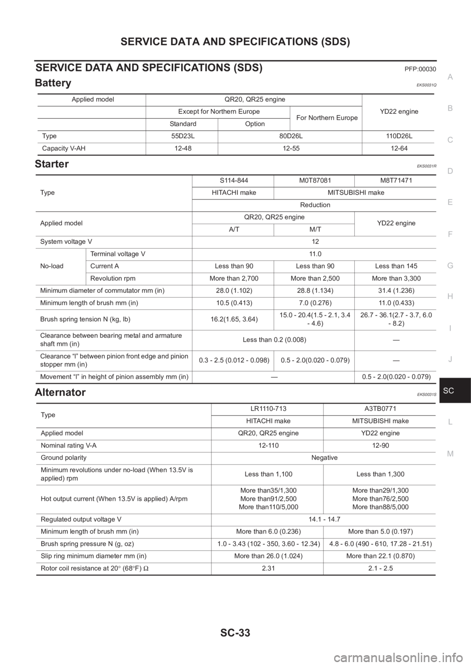
BatteryEKS0031Q
StarterEKS0031R
AlternatorEKS0031S
Applied model QR20, QR25 engine
YD22 engine Except for Northern Europe
For Northern Europe
Standard Option
Type 55D23L 80D26L 110D26L
Capacity V-AH 12-48 12-55 12-64
TypeS114-844 M0T87081 M8T71471
HITACHI make MITSUBISHI make
Reduction
Applied modelQR20, QR25 engine
YD22 engine
A/T M/T
System voltage V12
No-loadTerminal voltage V 11.0
Current A Less than 90 Less than 90 Less than 145
Revolution rpm More than 2,700 More than 2,500 More than 3,300
Minimum diameter of commutator mm (in) 28.0 (1.102) 28.8 (1.134) 31.4 (1.236)
Minimum length of brush mm (in) 10.5 (0.413) 7.0 (0.276) 11.0 (0.433)
Brush spring tension N (kg, lb) 16.2(1.65, 3.64)15.0 - 20.4(1.5 - 2.1, 3.4
- 4.6)26.7 - 36.1(2.7 - 3.7, 6.0
- 8.2)
Clearance between bearing metal and armature
shaft mm (in)Less than 0.2 (0.008) —
Clearance “l” between pinion front edge and pinion
stopper mm (in)0.3 - 2.5 (0.012 - 0.098) 0.5 - 2.0(0.020 - 0.079) —
Movement “l” in height of pinion assembly mm (in) — 0.5 - 2.0(0.020 - 0.079)
TypeLR1110-713 A3TB0771
HITACHI make MITSUBISHI make
Applied model QR20, QR25 engine YD22 engine
Nominal rating V-A 12-110 12-90
Ground polarityNegative
Minimum revolutions under no-load (When 13.5V is
applied) rpmLess than 1,100 Less than 1,300
Hot output current (When 13.5V is applied) A/rpmMore than35/1,300
More than91/2,500
More than110/5,000More than29/1,300
More than76/2,500
More than88/5,000
Regulated output voltage V 14.1 - 14.7
Minimum length of brush mm (in) More than 6.0 (0.236) More than 5.0 (0.197)
Brush spring pressure N (g, oz) 1.0 - 3.43 (102 - 350, 3.60 - 12.34) 4.8 - 6.0 (490 - 610, 17.28 - 21.51)
Slip ring minimum diameter mm (in) More than 26.0 (1.024) More than 22.1 (0.870)
Rotor coil resistance at 20° (68°F) Ω2.31 2.1 - 2.5
Page 3782 of 3833
MA-2
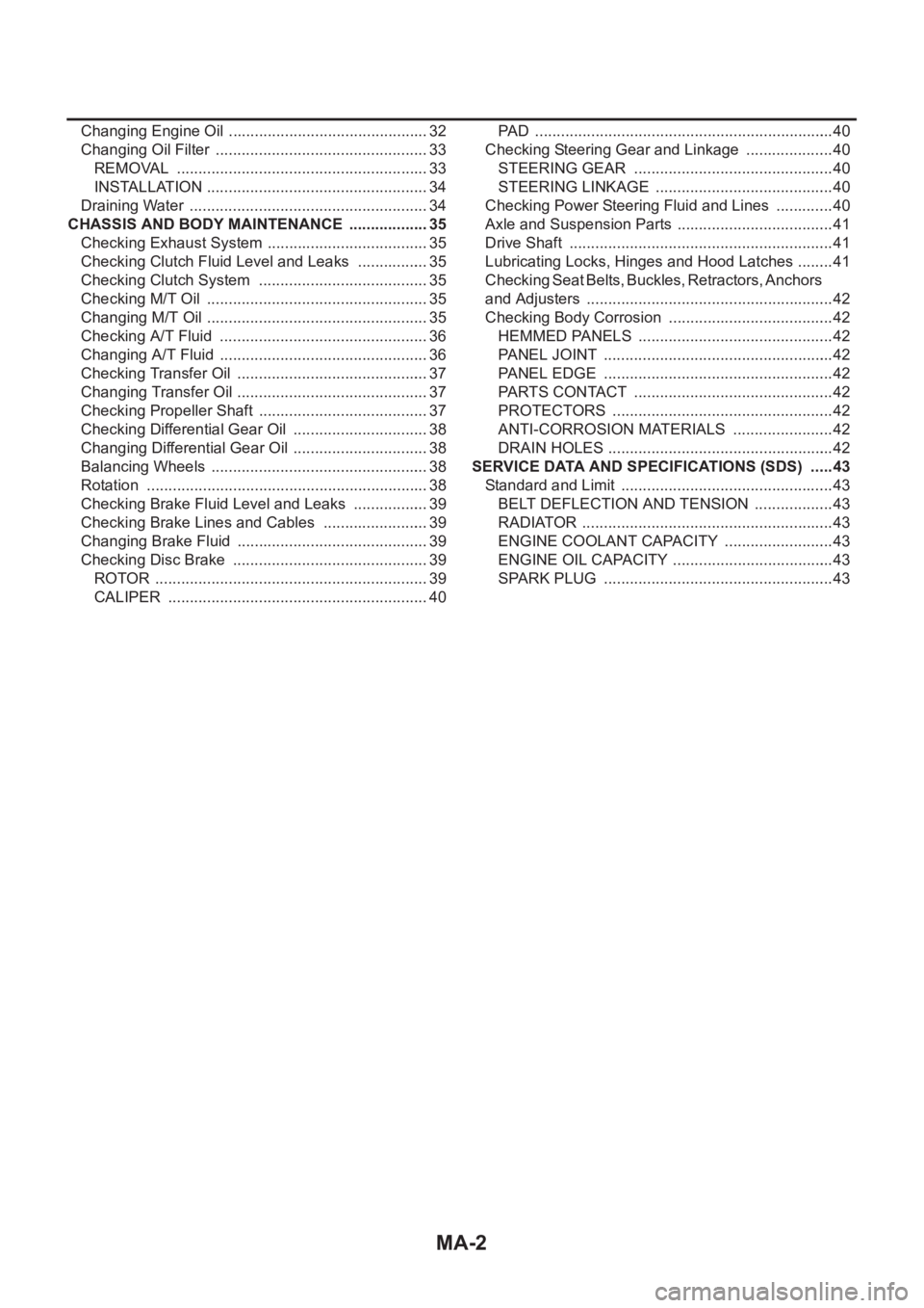
Changing Engine Oil ............................................ ... 32
Changing Oil Filter .................................................. 33
REMOVAL ........................................................... 33
INSTALLATION .................................................... 34
Draining Water ........................................................ 34
CHASSIS AND BODY MAINTENANCE ................... 35
Checking Exhaust System ...................................... 35
Checking Clutch Fluid Level and Leaks ................. 35
Checking Clutch System ........................................ 35
Checking M/T Oil .................................................... 35
Changing M/T Oil .................................................... 35
Checking A/T Fluid ................................................. 36
Changing A/T Fluid ................................................. 36
Checking Transfer Oil ............................................. 37
Changing Transfer Oil .......................................... ... 37
Checking Propeller Shaft ........................................ 37
Checking Differential Gear Oil ................................ 38
Changing Differential Gear Oil ................................ 38
Balancing Wheels ................................................... 38
Rotation .................................................................. 38
Checking Brake Fluid Level and Leaks .................. 39
Checking Brake Lines and Cables ......................... 39
Changing Brake Fluid ............................................. 39
Checking Disc Brake .............................................. 39
ROTOR ................................................................ 39
CALIPER ............................................................. 40PAD ...................................................................... 40
Checking Steering Gear and Linkage ..................... 40
STEERING GEAR ............................................... 40
STEERING LINKAGE .......................................... 40
Checking Power Steering Fluid and Lines .............. 40
Axle and Suspension Parts ..................................... 41
Drive Shaft .............................................................. 41
Lubricating Locks, Hinges and Hood Latches ......... 41
Checking Seat Belts, Buckles, Retractors, Anchors
and Adjusters .......................................................... 42
Checking Body Corrosion ....................................... 42
HEMMED PANELS .............................................. 42
PANEL JOINT ...................................................... 42
PANEL EDGE ...................................................... 42
PARTS CONTACT ............................................... 42
PROTECTORS .................................................... 42
ANTI-CORROSION MATERIALS ........................ 42
DRAIN HOLES ..................................................... 42
SERVICE DATA AND SPECIFICATIONS (SDS) ...... 43
Standard and Limit .................................................. 43
BELT DEFLECTION AND TENSION ................... 43
RADIATOR ........................................................... 43
ENGINE COOLANT CAPACITY .......................... 43
ENGINE OIL CAPACITY ...................................... 43
SPARK PLUG ...................................................... 43
Page 3796 of 3833
MA-16
RECOMMENDED FLUIDS AND LUBRICANTS
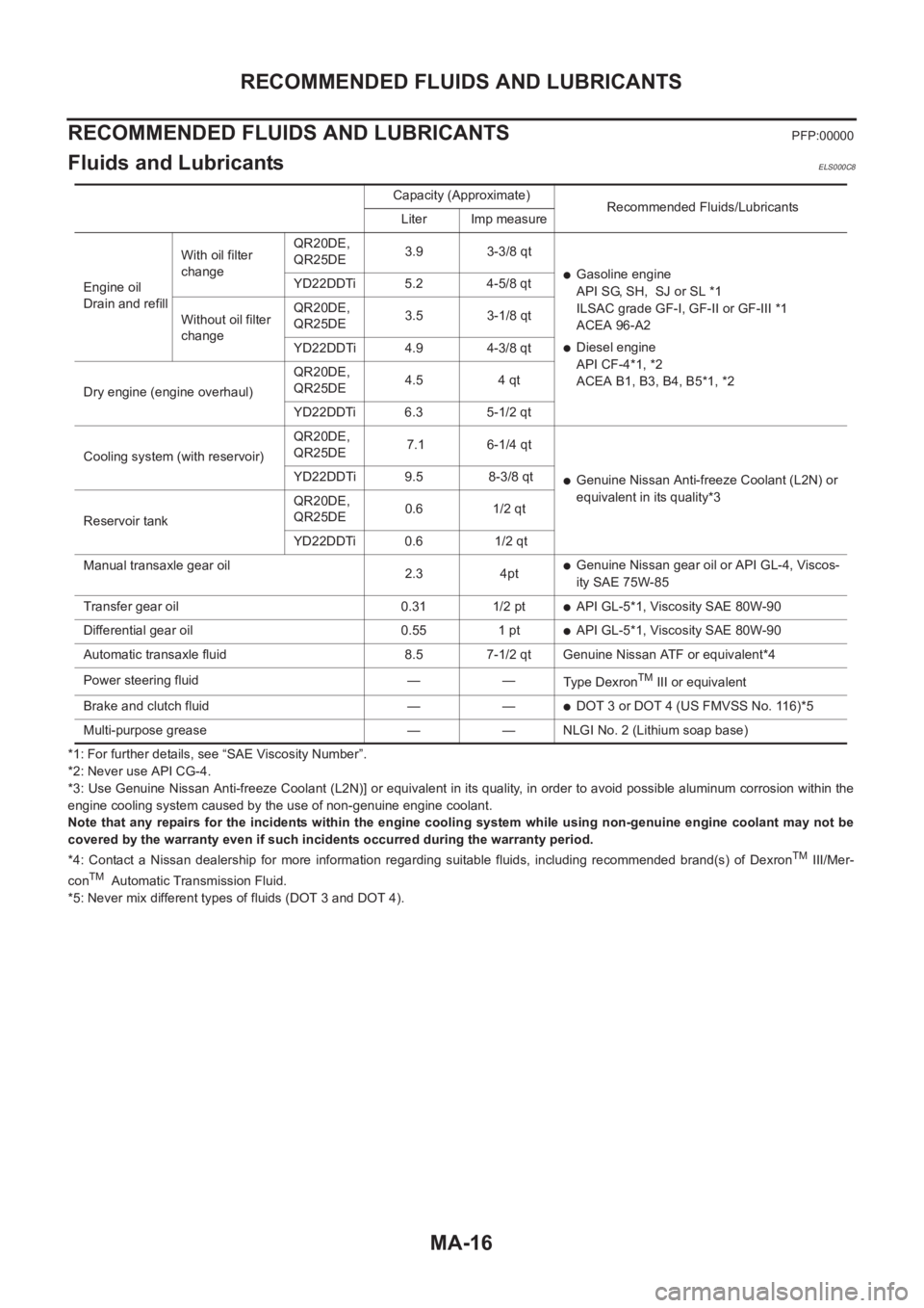
RECOMMENDED FLUIDS AND LUBRICANTS
PFP:00000
Fluids and LubricantsELS000C8
*1: For further details, see “SAE Viscosity Number”.
*2: Never use API CG-4.
*3: Use Genuine Nissan Anti-freeze Coolant (L2N)] or equivalent in its quality, in order to avoid possible aluminum corrosion within the
engine cooling system caused by the use of non-genuine engine coolant.
Note that any repairs for the incidents within the engine cooling system while using non-genuine engine coolant may not be
covered by the warranty even if such incidents occurred during the warranty period.
*4: Contact a Nissan dealership for more information regarding suitable fluids, including recommended brand(s) of Dexron
TM III/Mer-
conTM Automatic Transmission Fluid.
*5: Never mix different types of fluids (DOT 3 and DOT 4).Capacity (Approximate)
Recommended Fluids/Lubricants
Liter Imp measure
Engine oil
Drain and refillWith oil filter
changeQR20DE,
QR25DE3.9 3-3/8 qt
●Gasoline engine
API SG, SH, SJ or SL *1
ILSAC grade GF-I, GF-II or GF-III *1
ACEA 96-A2
●Diesel engine
API CF-4*1, *2
ACEA B1, B3, B4, B5*1, *2 YD22DDTi 5.2 4-5/8 qt
Without oil filter
changeQR20DE,
QR25DE3.5 3-1/8 qt
YD22DDTi 4.9 4-3/8 qt
Dry engine (engine overhaul)QR20DE,
QR25DE4.5 4 qt
YD22DDTi 6.3 5-1/2 qt
Cooling system (with reservoir)QR20DE,
QR25DE 7.1 6-1/4 qt
●Genuine Nissan Anti-freeze Coolant (L2N) or
equivalent in its quality*3 YD22DDTi 9.5 8-3/8 qt
Reservoir tankQR20DE,
QR25DE0.6 1/2 qt
YD22DDTi 0.6 1/2 qt
Manual transaxle gear oil
2.3 4pt
●Genuine Nissan gear oil or API GL-4, Viscos-
ity SAE 75W-85
Transfer gear oil 0.31 1/2 pt
●API GL-5*1, Viscosity SAE 80W-90
Differential gear oil 0.55 1 pt
●API GL-5*1, Viscosity SAE 80W-90
Automatic transaxle fluid 8.5 7-1/2 qt Genuine Nissan ATF or equivalent*4
Power steering fluid — —
Type Dexron
TM III or equivalent
Brake and clutch fluid — —
●DOT 3 or DOT 4 (US FMVSS No. 116)*5
Multi-purpose grease — — NLGI No. 2 (Lithium soap base)
Page 3803 of 3833
ENGINE MAINTENANCE (QR20DE·QR25DE)
MA-23
C
D
E
F
G
H
I
J
K
MA
B
MA
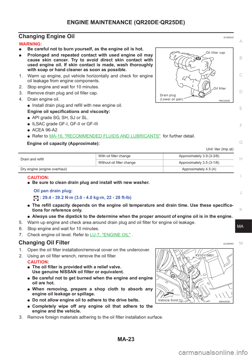
Changing Engine OilELS000JZ
WARNING:
●Be careful not to burn yourself, as the engine oil is hot.
●Prolonged and repeated contact with used engine oil may
cause skin cancer. Try to avoid direct skin contact with
used engine oil. If skin contact is made, wash thoroughly
with soap or hand cleaner as soon as possible.
1. Warm up engine, put vehicle horizontally and check for engine
oil leakage from engine components.
2. Stop engine and wait for 10 minutes.
3. Remove drain plug and oil filler cap.
4. Drain engine oil.
●Install drain plug and refill with new engine oil.
Engine oil specifications and viscosity:
●API grade SG, SH, SJ or SL.
●ILSAC grade GF-I, GF-II or GF-III
●ACEA 96-A2
●Refer to MA-16, "RECOMMENDED FLUIDS AND LUBRICANTS" for further detail.
Engine oil capacity (Approximate):
Unit: liter (lmp qt)
CAUTION:
●Be sure to clean drain plug and install with new washer.
●The refill capacity depends on the engine oil temperature and drain time. Use these specifica-
tions for reference only.
●Always use the dipstick to the determine when the proper amount of engine oil is in the engine.
5. Warm up engine and check area around drain plug and oil filter for engine oil leakage.
6. Stop engine and wait for 10 minutes.
7. Check engine oil level. Refer to LU-7, "
ENGINE OIL" .
Changing Oil FilterELS000K0
1. Open the oil filter installation/removal cover on the undercover.
2. Using an oil filter wrench, remove the oil filter.
CAUTION:
●The oil filter is provided with a relief valve.
Use genuine NISSAN oil filter or equivalent.
●Be careful not to get burned when the engine and engine
oil are hot.
●When removing, prepare a shop cloth to absorb any
engine oil leakage or spillage.
●Do not allow engine oil to adhere to the drive belts.
●Completely wipe off any engine oil that adhere to the
engine and the vehicle.
3. Remove foreign materials adhering to the oil filter installation surface.
PBIC0250E
Drain and refillWith oil filter change Approximately 3.9 (3-3/8)
Without oil filter change Approximately 3.5 (3-1/8)
Dry engine (engine overhaul)Approximately 4.5 (4)
Oil pan drain plug:
: 29.4 - 39.2 N·m (3.0 - 4.0 kg-m, 22 - 28 ft-lb)
KBIA0303E
Page 3812 of 3833

MA-32
ENGINE MAINTENANCE (YD22DDTI)
Changing Air Cleaner Filter
ELS000CG
VISCOUS PAPER TYPE
The viscous paper type air cleaner filter does not require any clean-
ing operation between renewal.
Changing Engine OilELS000CH
WARNING:
●Be careful not to burn yourself, as the engine oil is hot.
●Prolonged and repeated contact with used engine oil may
cause skin cancer: try to avoid direct skin contact with
used engine oil. If skin contact is made, wash thoroughly
with soap or hand cleaner as soon as possible.
1. Warm up engine, put vehicle horizontally and check for engine
oil leakage from engine components.
2. Stop engine and wait for 10 minutes.
3. Remove drain plug and oil filler cap.
4. Drain engine oil.
●Install drain plug and refill with new engine oil.
Engine oil specification and viscosity:
●API grade CF-4.
●ACEA B1, B3, B4, B5
●Refer to MA-16, "RECOMMENDED FLUIDS AND LUBRI-
CANTS" .
Engine oil capacity (Approximate):
●The refill capacity depends on the engine oil temperature and drain time. Use these specifications for
reference only.
Always use the dipstick to the determine when the proper amount of engine oil is in the engine.
CAUTION:
●Be sure to clean drain plug and install with new washer.
●The refill capacity depends on the engine oil temperature and drain time. Use these specifica-
tions for reference only.
Always use the dipstick to the determine when the proper amount of engine oil is in the
engine.
5. Warm up engine and check area around drain plug and oil filter for engine oil leakage.
6. Stop engine and wait for 10 minutes.
7. Check engine oil level. Refer to LU-18, "
ENGINE OIL" .
PBIC0526E
PBIC0527E
Drain and refillWith oil filter change
5.2 (4-5/8 Imp qt)
Without oil filter change
4.9 (4-3/8 Imp qt)
Dry engine (engine overhaul)6.3 (5-1/2 Imp qt)
Oil pan drain plug:
: 29 - 39 N·m (3.0 - 4.0 kg-m, 22 - 29 ft-lb)
SBIA0122E
Page 3814 of 3833

MA-34
ENGINE MAINTENANCE (YD22DDTI)
4. Remove the O-ring from the filter body.
●Push the O-ring in one direction, lift the slack part using fin-
gers, and remove the O-ring from the filter body.
CAUTION:
Do not use wires or flat-bladed screwdrivers etc. as they
may cause damage to the filter body.
INSTALLATION
1. Completely remove all foreign objects adhering to the inside of the filter body or O-ring mounting area
(body side and bracket side).
2. Install the oil filter and O-ring to the filter body.
●Push the oil filter into the filter body completely.
3. Install the filter body to the oil filter bracket.
4. After warming up the engine, check for engine oil leakage.
5. Check engine oil level and add engine oil. Refer to LU-18, "
ENGINE OIL" .
Draining WaterELS000CJ
1. Prepare a tray at the drain hose open end.
2. Loosen drain cock, and operate priming pump to drain water
from fuel filter.
CAUTION:
●Water in filter is drained with fuel. Prepare larger capacity
pan than fuel filter volume.
●Drained water is mixed with fuel. Prevent fuel from adher-
ing to rubber parts such as engine mount insulator.
3. After draining, close drain cock by hand.
CAUTION:
If drain cock is tightened excessively, it may be damaged
and fuel will leak. Do not use tools to tighten drain cock.
4. Bleed air in fuel piping. Refer to FL-16, "
Air Bleeding" .
5. Start engine and check fuel leakage.
JLC292B
Oil filter:
: 20 - 24 N·m (2.0 - 2.5 Kg-m, 15 - 18 ft-lb)
SBIA0138E