sunroof NISSAN X-TRAIL 2001 Service User Guide
[x] Cancel search | Manufacturer: NISSAN, Model Year: 2001, Model line: X-TRAIL, Model: NISSAN X-TRAIL 2001Pages: 3833, PDF Size: 39.49 MB
Page 3219 of 3833
SUNROOF
RF-11
C
D
E
F
G
H
J
K
L
MA
B
RF
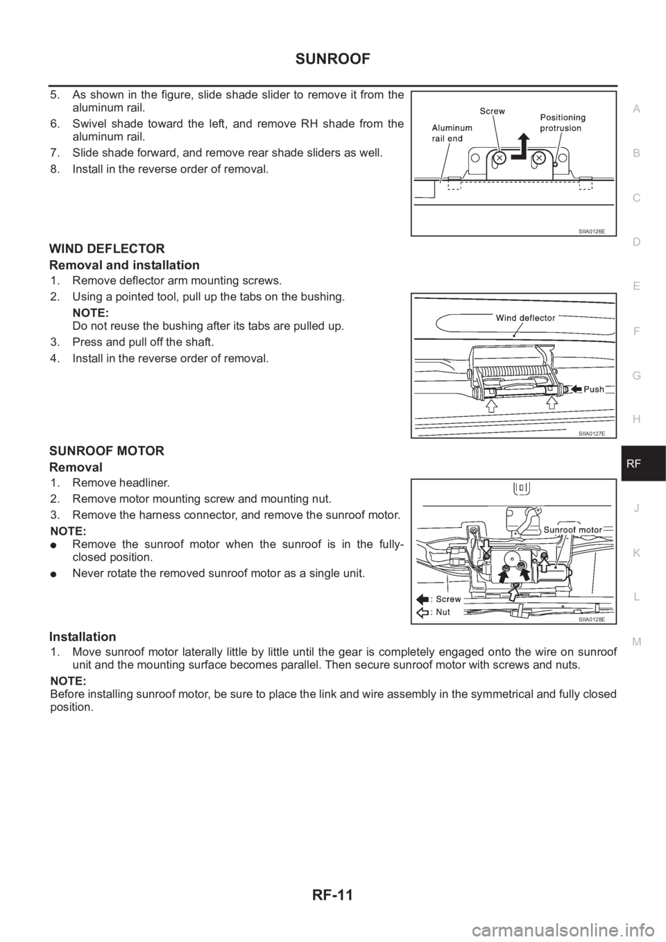
5. As shown in the figure, slide shade slider to remove it from the
aluminum rail.
6. Swivel shade toward the left, and remove RH shade from the
aluminum rail.
7. Slide shade forward, and remove rear shade sliders as well.
8. Install in the reverse order of removal.
WIND DEFLECTOR
Removal and installation
1. Remove deflector arm mounting screws.
2. Using a pointed tool, pull up the tabs on the bushing.
NOTE:
Do not reuse the bushing after its tabs are pulled up.
3. Press and pull off the shaft.
4. Install in the reverse order of removal.
SUNROOF MOTOR
Removal
1. Remove headliner.
2. Remove motor mounting screw and mounting nut.
3. Remove the harness connector, and remove the sunroof motor.
NOTE:
●Remove the sunroof motor when the sunroof is in the fully-
closed position.
●Never rotate the removed sunroof motor as a single unit.
Installation
1. Move sunroof motor laterally little by little until the gear is completely engaged onto the wire on sunroof
unit and the mounting surface becomes parallel. Then secure sunroof motor with screws and nuts.
NOTE:
Before installing sunroof motor, be sure to place the link and wire assembly in the symmetrical and fully closed
position.
SIIA0126E
SIIA0127E
SIIA0128E
Page 3220 of 3833
RF-12
SUNROOF
Page 3249 of 3833
HEADLINING
EI-29
C
D
E
F
G
H
J
K
L
MA
B
EI
HEADLININGPFP:73910
Removal and InstallationEIS000ND
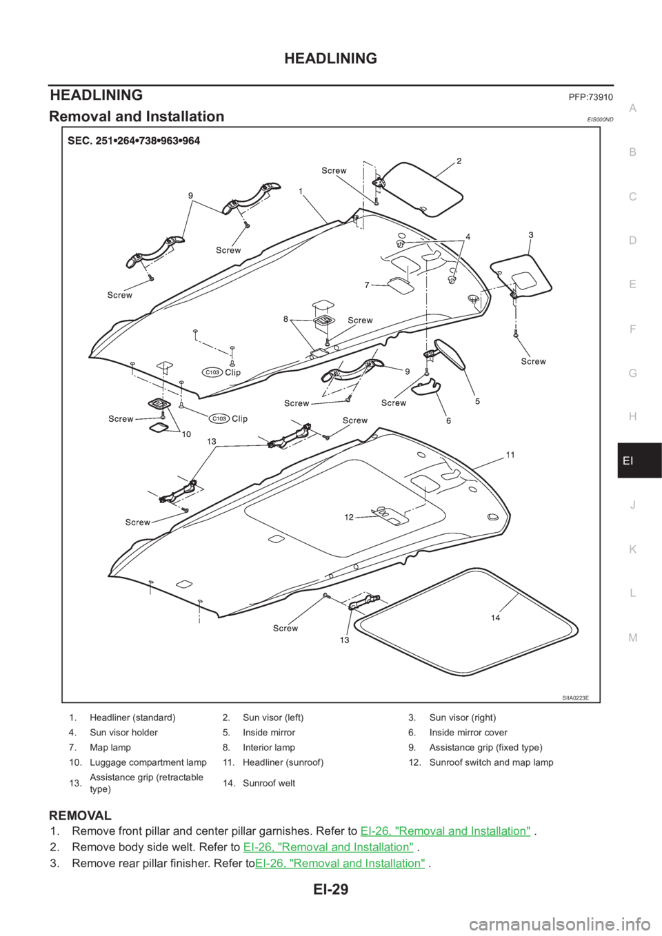
REMOVAL
1. Remove front pillar and center pillar garnishes. Refer to EI-26, "Removal and Installation" .
2. Remove body side welt. Refer to EI-26, "
Removal and Installation" .
3. Remove rear pillar finisher. Refer toEI-26, "
Removal and Installation" .
SIIA0223E
1. Headliner (standard) 2. Sun visor (left) 3. Sun visor (right)
4. Sun visor holder 5. Inside mirror 6. Inside mirror cover
7. Map lamp 8. Interior lamp 9. Assistance grip (fixed type)
10. Luggage compartment lamp 11. Headliner (sunroof) 12. Sunroof switch and map lamp
13.Assistance grip (retractable
type)14. Sunroof welt
Page 3250 of 3833
EI-30
HEADLINING
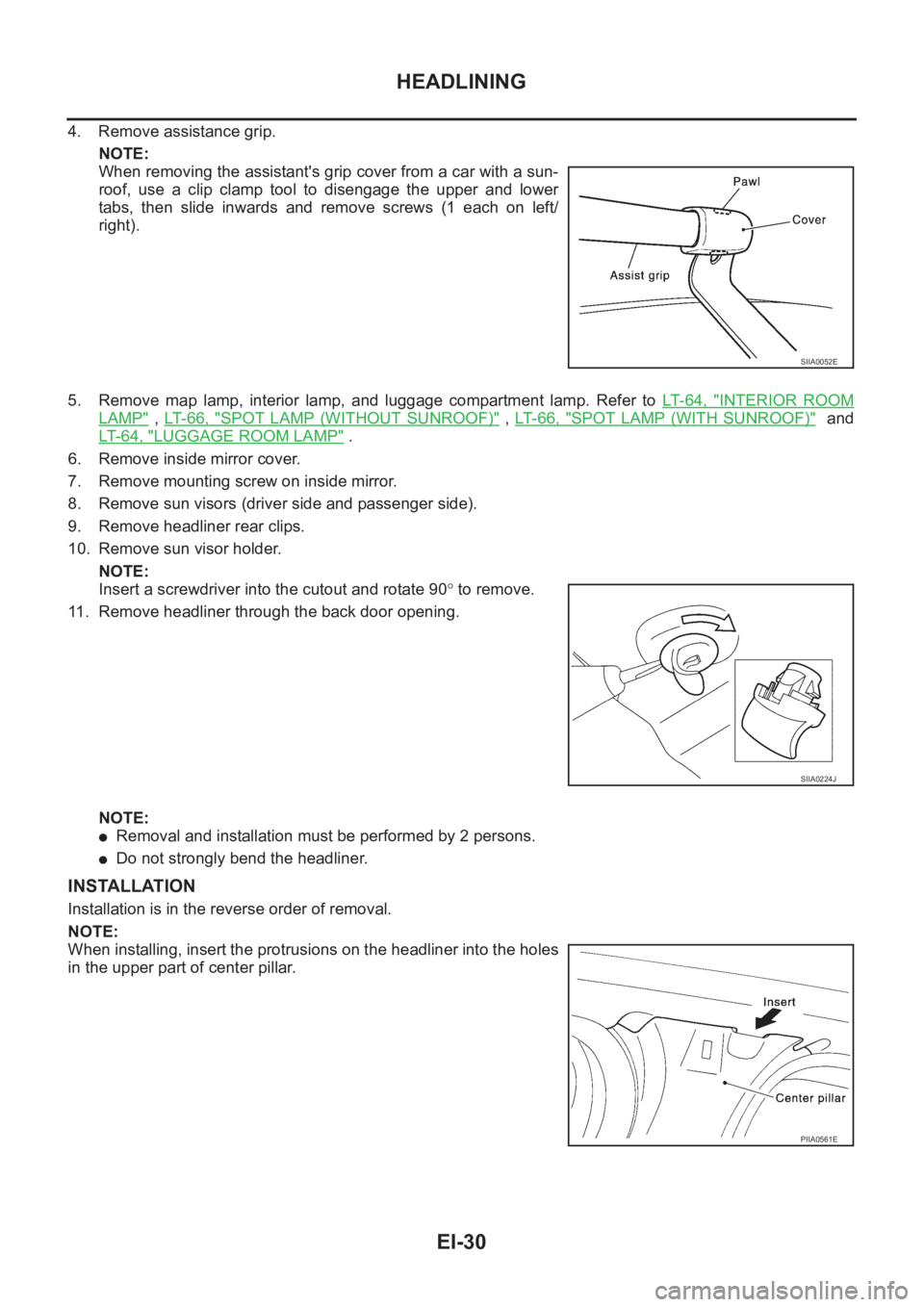
4. Remove assistance grip.
NOTE:
When removing the assistant's grip cover from a car with a sun-
roof, use a clip clamp tool to disengage the upper and lower
tabs, then slide inwards and remove screws (1 each on left/
right).
5. Remove map lamp, interior lamp, and luggage compartment lamp. Refer to LT- 6 4 , "
INTERIOR ROOM
LAMP" , LT- 6 6 , "SPOT LAMP (WITHOUT SUNROOF)" , LT- 6 6 , "SPOT LAMP (WITH SUNROOF)" and
LT- 6 4 , "
LUGGAGE ROOM LAMP" .
6. Remove inside mirror cover.
7. Remove mounting screw on inside mirror.
8. Remove sun visors (driver side and passenger side).
9. Remove headliner rear clips.
10. Remove sun visor holder.
NOTE:
Insert a screwdriver into the cutout and rotate 90° to remove.
11. Remove headliner through the back door opening.
NOTE:
●Removal and installation must be performed by 2 persons.
●Do not strongly bend the headliner.
INSTALLATION
Installation is in the reverse order of removal.
NOTE:
When installing, insert the protrusions on the headliner into the holes
in the upper part of center pillar.
SIIA0052E
SIIA0224J
PIIA0561E
Page 3492 of 3833
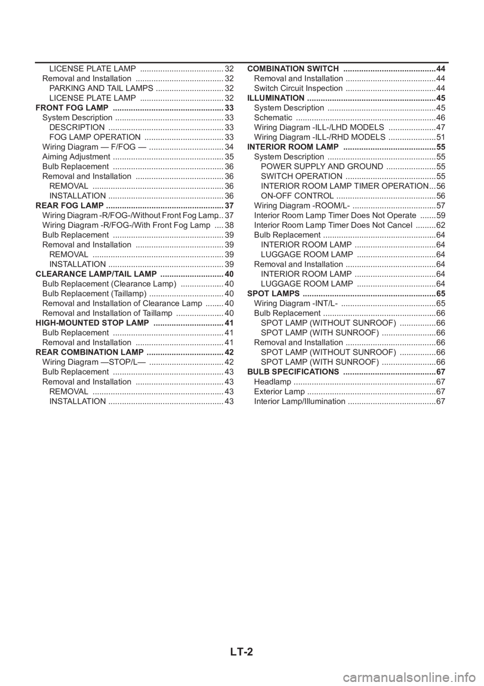
LT-2
LICENSE PLATE LAMP ...................................... 32
Removal and Installation ........................................ 32
PARKING AND TAIL LAMPS ............................... 32
LICENSE PLATE LAMP ...................................... 32
FRONT FOG LAMP .................................................. 33
System Description ................................................. 33
DESCRIPTION .................................................... 33
FOG LAMP OPERATION .................................... 33
Wiring Diagram — F/FOG — .................................. 34
Aiming Adjustment .................................................. 35
Bulb Replacement .................................................. 36
Removal and Installation ........................................ 36
REMOVAL ........................................................... 36
INSTALLATION .................................................... 36
REAR FOG LAMP .................................................. ... 37
Wiring Diagram -R/FOG-/Without Front Fog Lamp ... 37
Wiring Diagram -R/FOG-/With Front Fog Lamp ..... 38
Bulb Replacement .................................................. 39
Removal and Installation ........................................ 39
REMOVAL ........................................................... 39
INSTALLATION .................................................... 39
CLEARANCE LAMP/TAIL LAMP ............................. 40
Bulb Replacement (Clearance Lamp) .................... 40
Bulb Replacement (Taillamp) .................................. 40
Removal and Installation of Clearance Lamp ......... 40
Removal and Installation of Taillamp ...................... 40
HIGH-MOUNTED STOP LAMP ................................ 41
Bulb Replacement .................................................. 41
Removal and Installation ........................................ 41
REAR COMBINATION LAMP ................................... 42
Wiring Diagram —STOP/L— .................................. 42
Bulb Replacement .................................................. 43
Removal and Installation ........................................ 43
REMOVAL ........................................................... 43
INSTALLATION .................................................... 43COMBINATION SWITCH .......................................... 44
Removal and Installation ......................................... 44
Switch Circuit Inspection ...................................... ... 44
ILLUMINATION .......................................................... 45
System Description ................................................. 45
Schematic ............................................................... 46
Wiring Diagram -ILL-/LHD MODELS ...................... 47
Wiring Diagram -ILL-/RHD MODELS ...................... 51
INTERIOR ROOM LAMP .......................................
... 55
System Description ................................................. 55
POWER SUPPLY AND GROUND ....................... 55
SWITCH OPERATION ......................................... 55
INTERIOR ROOM LAMP TIMER OPERATION ... 56
ON-OFF CONTROL ............................................. 56
Wiring Diagram -ROOM/L- ...................................... 57
Interior Room Lamp Timer Does Not Operate ........ 59
Interior Room Lamp Timer Does Not Cancel .......... 62
Bulb Replacement ................................................... 64
INTERIOR ROOM LAMP ..................................... 64
LUGGAGE ROOM LAMP .................................... 64
Removal and Installation ......................................... 64
INTERIOR ROOM LAMP ..................................... 64
LUGGAGE ROOM LAMP .................................... 64
SPOT LAMPS ............................................................ 65
Wiring Diagram -INT/L- ........................................... 65
Bulb Replacement ................................................... 66
SPOT LAMP (WITHOUT SUNROOF) ................. 66
SPOT LAMP (WITH SUNROOF) ......................... 66
Removal and Installation ......................................... 66
SPOT LAMP (WITHOUT SUNROOF) ................. 66
SPOT LAMP (WITH SUNROOF) ......................... 66
BULB SPECIFICATIONS .......................................... 67
Headlamp ................................................................ 67
Exterior Lamp .......................................................... 67
Interior Lamp/Illumination ........................................ 67
Page 3556 of 3833
LT-66
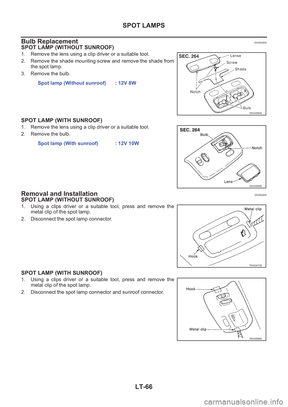
SPOT LAMPS
Bulb Replacement
EKS003DD
SPOT LAMP (WITHOUT SUNROOF)
1. Remove the lens using a clip driver or a suitable tool.
2. Remove the shade mounting screw and remove the shade from
the spot lamp.
3. Remove the bulb.
SPOT LAMP (WITH SUNROOF)
1. Remove the lens using a clip driver or a suitable tool.
2. Remove the bulb.
Removal and InstallationEKS003DE
SPOT LAMP (WITHOUT SUNROOF)
1. Using a clips driver or a suitable tool, press and remove the
metal clip of the spot lamp.
2. Disconnect the spot lamp connector.
SPOT LAMP (WITH SUNROOF)
1. Using a clips driver or a suitable tool, press and remove the
metal clip of the spot lamp.
2. Disconnect the spot lamp connector and sunroof connector.Spot lamp (Without sunroof) : 12V 8W
SKIA0064E
Spot lamp (With sunroof) : 12V 10W
SKIA0065E
PKIA0472E
SKIA0066E
Page 3557 of 3833
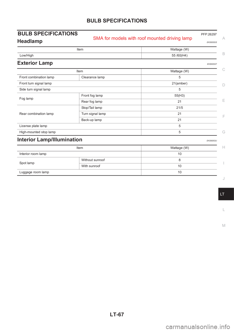
BULB SPECIFICATIONS
LT-67
C
D
E
F
G
H
I
J
L
MA
B
LT
BULB SPECIFICATIONSPFP:26297
HeadlampEKS003GS
Exterior LampEKS003GT
Interior Lamp/IlluminationEKS003GU
Item Wattage (W)
Low/High55 /60(H4)
Item Wattage (W)
Front combination lamp Clearance lamp 5
Front turn signal lamp21(amber)
Side turn signal lamp5
Fog lampFront fog lamp 55(H3)
Rear fog lamp 21
Rear combination lampStop/Tail lamp 21/5
Turn signal lamp 21
Back-up lamp 21
License plate lamp5
High-mounted stop lamp5
Item Wattage (W)
Interior room lamp10
Spot lampWithout sunroof 8
With sunroof 10
Luggage room lamp10
SMA for models with roof mounted driving lamp
Page 3766 of 3833
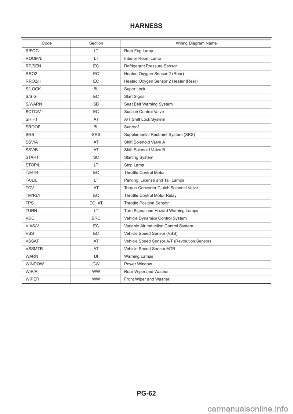
PG-62
HARNESS
R/FOG LT Rear Fog Lamp
ROOM/L LT Interior Room Lamp
RP/SEN EC Refrigerant Pressure Sensor
RRO2 EC Heated Oxygen Sensor 2 (Rear)
RRO2/H EC Heated Oxygen Sensor 2 Heater (Rear)
S/LOCK BL Super Lock
S/SIG EC Start Signal
S/WARN SB Seat Belt Warning System
SCTC/V EC Suction Control Valve
SHIFT AT A/T Shift Lock System
SROOF BL Sunroof
SRS SRS Supplemental Restraint System (SRS)
SSV/A AT Shift Solenoid Valve A
SSV/B AT Shift Solenoid Valve B
START SC Starting System
STOP/L LT Stop Lamp
T/MTR EC Throttle Control Motor
TAIL/L LT Parking, License and Tail Lamps
TCV AT Torque Converter Clutch Solenoid Valve
TM/RLY EC Throttle Control Motor Relay
TPS EC, AT Throttle Position Sensor
TURN LT Turn Signal and Hazard Warning Lamps
VDC BRC Vehicle Dynamics Control System
VIAS/V EC Variable Air Induction Control System
VSS EC Vehicle Speed Sensor (VSS)
VSSAT AT Vehicle Speed Sensor A/T (Revolution Sensor)
VSSMTR AT Vehicle Speed Sensor MTR
WARN DI Warning Lamps
WINDOW GW Power Window
WIP/R WW Rear Wiper and Washer
WIPER WW Front Wiper and WasherCode Section Wiring Diagram Name
Page 3822 of 3833

MA-42
CHASSIS AND BODY MAINTENANCE
Checking Seat Belts, Buckles, Retractors, Anchors and Adjusters
ELS000BS
Checking Body CorrosionELS000C0
Visually check body panels for collision damage (scratches, chipping, rubbing, etc.) or damage to the anti-cor-
rosion materials. In particular, check the following locations.
HEMMED PANELS
Hood front end, door lower end, trunk lid rear end, etc.
PANEL JOINT
Side sill of rear fender and center pillar, rear wheel housing of rear fender, around strut tower in engine com-
partment, etc.
PANEL EDGE
Trunk lid opening, sunroof opening, fender wheel-arch flange, fuel filler lid flange, around holes in panel, etc.
PARTS CONTACT
Waist moulding, windshield moulding, bumper, etc.
PROTECTORS
Damage or condition of mudguard, fender protector, chipping protector, etc.
ANTI-CORROSION MATERIALS
Damage or separation of anti-corrosion materials under the body.
DRAIN HOLES
Condition of drain holes at door and side sill. When repairing corroded areas, refer to the Corrosion Repair
Manual.
Page 3828 of 3833
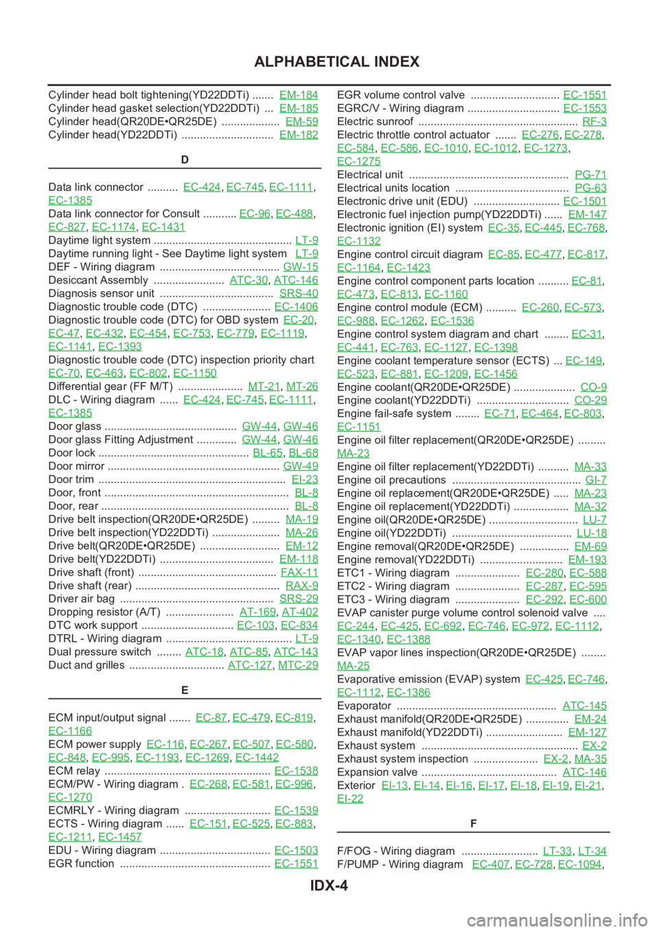
IDX-4
ALPHABETICAL INDEX
Cylinder head bolt tightening(YD22DDTi) ....... EM-184
Cylinder head gasket selection(YD22DDTi) ... EM-185
Cylinder head(QR20DE•QR25DE) ................... EM-59
Cylinder head(YD22DDTi) .............................. EM-182
D
Data link connector .......... EC-424
,EC-745,EC-1111,
EC-1385
Data link connector for Consult ........... EC-96,EC-488,
EC-827
,EC-1174,EC-1431
Daytime light system ............................................. LT-9
Daytime running light - See Daytime light system LT-9
DEF - Wiring diagram ....................................... GW-15
Desiccant Assembly ....................... ATC-30,ATC-146
Diagnosis sensor unit ..................................... SRS-40
Diagnostic trouble code (DTC) ...................... EC-1406
Diagnostic trouble code (DTC) for OBD system EC-20,
EC-47
,EC-432,EC-454,EC-753,EC-779,EC-1119,
EC-1141
,EC-1393
Diagnostic trouble code (DTC) inspection priority chart
EC-70
,EC-463,EC-802,EC-1150
Differential gear (FF M/T) ..................... MT-21,MT-26
DLC - Wiring diagram ...... EC-424,EC-745,EC-1111,
EC-1385
Door glass ........................................... GW-44,GW-46
Door glass Fitting Adjustment ............. GW-44,GW-46
Door lock ................................................. BL-65,BL-68
Door mirror ........................................................ GW-49
Door trim ............................................................. EI-23
Door, front ............................................................ BL-8
Door, rear ............................................................. BL-8
Drive belt inspection(QR20DE•QR25DE) ......... MA-19
Drive belt inspection(YD22DDTi) ...................... MA-26
Drive belt(QR20DE•QR25DE) .......................... EM-12
Drive belt(YD22DDTi) ..................................... EM-118
Drive shaft (front) ............................................. FAX-11
Drive shaft (rear) ............................................... RAX-9
Driver air bag .................................................. SRS-29
Dropping resistor (A/T) ...................... AT-169,AT-402
DTC work support .............................. EC-103,EC-834
DTRL - Wiring diagram ......................................... LT-9
Dual pressure switch ........ ATC-18,ATC-85,ATC-143
Duct and grilles ............................... ATC-127,MTC-29
E
ECM input/output signal ....... EC-87
,EC-479,EC-819,
EC-1166
ECM power supply EC-116,EC-267,EC-507,EC-580,
EC-848
,EC-995,EC-1193,EC-1269,EC-1442
ECM relay ...................................................... EC-1538
ECM/PW - Wiring diagram . EC-268,EC-581,EC-996,
EC-1270
ECMRLY - Wiring diagram ............................ EC-1539
ECTS - Wiring diagram ...... EC-151,EC-525,EC-883,
EC-1211
,EC-1457
EDU - Wiring diagram .................................... EC-1503
EGR function ................................................. EC-1551
EGR volume control valve ............................. EC-1551
EGRC/V - Wiring diagram .............................. EC-1553
Electric sunroof .................................................... RF-3
Electric throttle control actuator ....... EC-276,EC-278,
EC-584
,EC-586,EC-1010,EC-1012,EC-1273,
EC-1275
Electrical unit .................................................... PG-71
Electrical units location ..................................... PG-63
Electronic drive unit (EDU) ............................ EC-1501
Electronic fuel injection pump(YD22DDTi) ...... EM-147
Electronic ignition (EI) system EC-35,EC-445,EC-768,
EC-1132
Engine control circuit diagram EC-85,EC-477,EC-817,
EC-1164
,EC-1423
Engine control component parts location .......... EC-81,
EC-473
,EC-813,EC-1160
Engine control module (ECM) .......... EC-260,EC-573,
EC-988
,EC-1262,EC-1536
Engine control system diagram and chart ........ EC-31,
EC-441
,EC-763,EC-1127,EC-1398
Engine coolant temperature sensor (ECTS) ... EC-149,
EC-523
,EC-881,EC-1209,EC-1456
Engine coolant(QR20DE•QR25DE) .................... CO-9
Engine coolant(YD22DDTi) .............................. CO-29
Engine fail-safe system ........ EC-71,EC-464,EC-803,
EC-1151
Engine oil filter replacement(QR20DE•QR25DE) .........
MA-23
Engine oil filter replacement(YD22DDTi) .......... MA-33
Engine oil precautions .......................................... GI-7
Engine oil replacement(QR20DE•QR25DE) ..... MA-23
Engine oil replacement(YD22DDTi) .................. MA-32
Engine oil(QR20DE•QR25DE) ............................. LU-7
Engine oil(YD22DDTi) ....................................... LU-18
Engine removal(QR20DE•QR25DE) ................ EM-69
Engine removal(YD22DDTi) ........................... EM-193
ETC1 - Wiring diagram ..................... EC-280,EC-588
ETC2 - Wiring diagram ..................... EC-287,EC-595
ETC3 - Wiring diagram ..................... EC-292,EC-600
EVAP canister purge volume control solenoid valve ....
EC-244
,EC-425,EC-692,EC-746,EC-972,EC-1112,
EC-1340
,EC-1388
EVAP vapor lines inspection(QR20DE•QR25DE) ........
MA-25
Evaporative emission (EVAP) system EC-425,EC-746,
EC-1112
,EC-1386
Evaporator .................................................... ATC-145
Exhaust manifold(QR20DE•QR25DE) .............. EM-24
Exhaust manifold(YD22DDTi) ......................... EM-127
Exhaust system ................................................... EX-2
Exhaust system inspection ..................... EX-2,MA-35
Expansion valve ............................................ ATC-146
Exterior EI-13,EI-14,EI-16,EI-17,EI-18,EI-19,EI-21,
EI-22
F
F/FOG - Wiring diagram ......................... LT-33
,LT-34
F/PUMP - Wiring diagram EC-407,EC-728,EC-1094,