check engine NISSAN X-TRAIL 2001 Service Owner's Manual
[x] Cancel search | Manufacturer: NISSAN, Model Year: 2001, Model line: X-TRAIL, Model: NISSAN X-TRAIL 2001Pages: 3833, PDF Size: 39.49 MB
Page 103 of 3833
CAMSHAFT
EM-53
[QR]
C
D
E
F
G
H
I
J
K
L
MA
EM
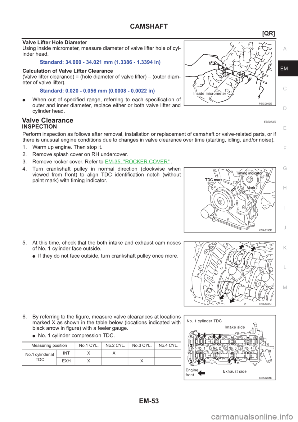
Valve Lifter Hole Diameter
Using inside micrometer, measure diameter of valve lifter hole of cyl-
inder head.
Calculation of Valve Lifter Clearance
(Valve lifter clearance) = (hole diameter of valve lifter) – (outer diam-
eter of valve lifter).
●When out of specified range, referring to each specification of
outer and inner diameter, replace either or both valve lifter and
cylinder head.
Va l v e C l e a r a n c eEBS00LS3
INSPECTION
Perform inspection as follows after removal, installation or replacement of camshaft or valve-related parts, or if
there is unusual engine conditions due to changes in valve clearance over time (starting, idling, and/or noise).
1. Warm up engine. Then stop it.
2. Remove splash cover on RH undercover.
3. Remove rocker cover. Refer to EM-35, "
ROCKER COVER" .
4. Turn crankshaft pulley in normal direction (clockwise when
viewed from front) to align TDC identification notch (without
paint mark) with timing indicator.
5. At this time, check that the both intake and exhaust cam noses
of No. 1 cylinder face outside.
●If they do not face outside, turn crankshaft pulley once more.
6. By referring to the figure, measure valve clearances at locations
marked X as shown in the table below (locations indicated with
black arrow in figure) with a feeler gauge.
●No. 1 cylinder compression TDC.Standard: 34.000 - 34.021 mm (1.3386 - 1.3394 in)
Standard: 0.020 - 0.056 mm (0.0008 - 0.0022 in)
PBIC0043E
KBIA0190E
KBIA0400J
Measuring position No.1 CYL. No.2 CYL. No.3 CYL. No.4 CYL.
No.1 cylinder at
TDCINT X X
EXH X X
SBIA0261E
Page 104 of 3833
EM-54
[QR]
CAMSHAFT
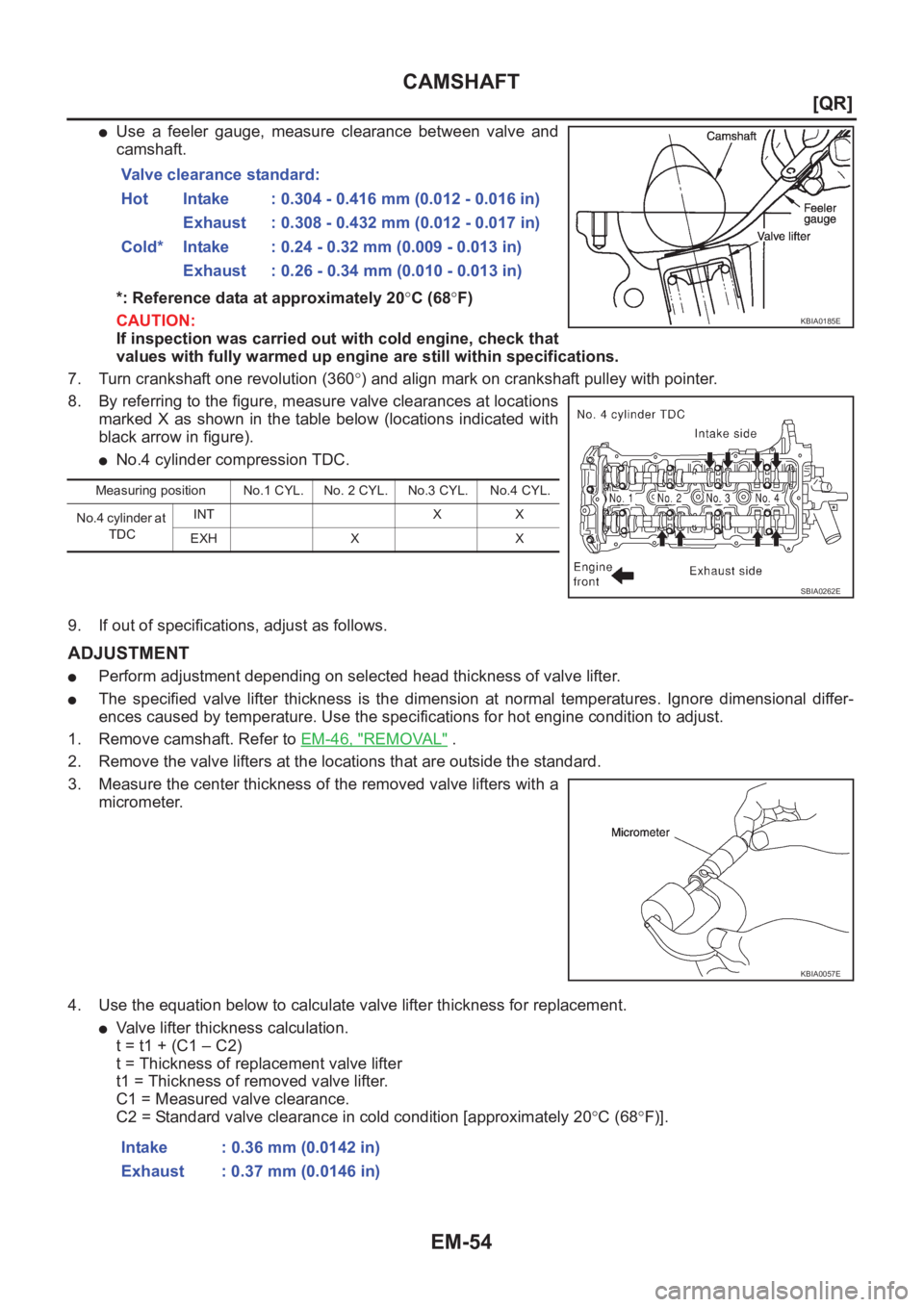
●Use a feeler gauge, measure clearance between valve and
camshaft.
*: Reference data at approximately 20°C (68°F)
CAUTION:
If inspection was carried out with cold engine, check that
values with fully warmed up engine are still within specifications.
7. Turn crankshaft one revolution (360°) and align mark on crankshaft pulley with pointer.
8. By referring to the figure, measure valve clearances at locations
marked X as shown in the table below (locations indicated with
black arrow in figure).
●No.4 cylinder compression TDC.
9. If out of specifications, adjust as follows.
ADJUSTMENT
●Perform adjustment depending on selected head thickness of valve lifter.
●The specified valve lifter thickness is the dimension at normal temperatures. Ignore dimensional differ-
ences caused by temperature. Use the specifications for hot engine condition to adjust.
1. Remove camshaft. Refer to EM-46, "
REMOVAL" .
2. Remove the valve lifters at the locations that are outside the standard.
3. Measure the center thickness of the removed valve lifters with a
micrometer.
4. Use the equation below to calculate valve lifter thickness for replacement.
●Valve lifter thickness calculation.
t = t1 + (C1 – C2)
t = Thickness of replacement valve lifter
t1 = Thickness of removed valve lifter.
C1 = Measured valve clearance.
C2 = Standard valve clearance in cold condition [approximately 20°C (68°F)]. Valve clearance standard:
Hot Intake : 0.304 - 0.416 mm (0.012 - 0.016 in)
Exhaust : 0.308 - 0.432 mm (0.012 - 0.017 in)
Cold* Intake : 0.24 - 0.32 mm (0.009 - 0.013 in)
Exhaust : 0.26 - 0.34 mm (0.010 - 0.013 in)
Measuring position No.1 CYL. No. 2 CYL. No.3 CYL. No.4 CYL.
No.4 cylinder at
TDCINT X X
EXH X X
KBIA0185E
SBIA0262E
KBIA0057E
Intake : 0.36 mm (0.0142 in)
Exhaust : 0.37 mm (0.0146 in)
Page 105 of 3833
CAMSHAFT
EM-55
[QR]
C
D
E
F
G
H
I
J
K
L
MA
EM
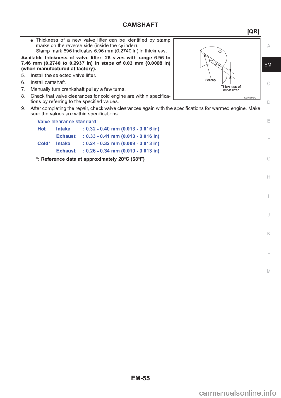
●Thickness of a new valve lifter can be identified by stamp
marks on the reverse side (inside the cylinder).
Stamp mark 696 indicates 6.96 mm (0.2740 in) in thickness.
Available thickness of valve lifter: 26 sizes with range 6.96 to
7.46 mm (0.2740 to 0.2937 in) in steps of 0.02 mm (0.0008 in)
(when manufactured at factory).
5. Install the selected valve lifter.
6. Install camshaft.
7. Manually turn crankshaft pulley a few turns.
8. Check that valve clearances for cold engine are within specifica-
tions by referring to the specified values.
9. After completing the repair, check valve clearances again with the specifications for warmed engine. Make
sure the values are within specifications.
*: Reference data at approximately 20°C (68°F) Valve clearance standard:
Hot Intake : 0.32 - 0.40 mm (0.013 - 0.016 in)
Exhaust : 0.33 - 0.41 mm (0.013 - 0.016 in)
Cold* Intake : 0.24 - 0.32 mm (0.009 - 0.013 in)
Exhaust : 0.26 - 0.34 mm (0.010 - 0.013 in)
KBIA0119E
Page 109 of 3833
CYLINDER HEAD
EM-59
[QR]
C
D
E
F
G
H
I
J
K
L
MA
EM
CYLINDER HEADPFP:11041
On-Vehicle ServiceEBS00KNP
CHECKING COMPRESSION PRESSURE
1. Warm up engine thoroughly. Then, stop it.
2. Release fuel pressure. Refer to EC-775, "
FUEL PRESSURE RELEASE" [QR20DE (WITH EURO-OBD)],
EC-1139, "
FUEL PRESSURE RELEASE" [QR20DE (WITHOUT EURO-OBD)], EC-42, "FUEL PRES-
SURE RELEASE" [QR25DE (WITH EURO-OBD)] or EC-452, "FUEL PRESSURE RELEASE" [QR25DE
(WITHOUT EURO-OBD)].
3. Remove ignition coil and spark plug from each cylinder. Refer to EM-29, "
IGNITION COIL" and EM-30,
"SPARK PLUG" .
4. Connect engine tachometer (not required in use of CONSULT-II).
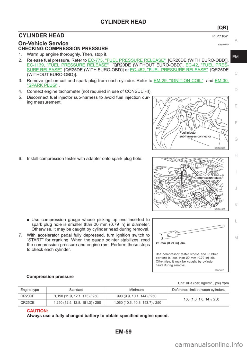
5. Disconnect fuel injector sub-harness to avoid fuel injection dur-
ing measurement.
6. Install compression tester with adapter onto spark plug hole.
●Use compression gauge whose picking up end inserted to
spark plug hole is smaller than 20 mm (0.79 in) in diameter.
Otherwise, it may be caught by cylinder head during removal.
7. With accelerator pedal fully depressed, turn ignition switch to
“START” for cranking. When the gauge pointer stabilizes, read
the compression pressure and engine rpm. Perform these steps
to check each cylinder.
Compression pressure
Unit: kPa (bar, kg/cm2 , psi) /rpm
CAUTION:
Always use a fully changed battery to obtain specified engine speed.
KBIA0269E
KBIA0130E
SEM387C
Engine type Standard Minimum Deference limit between cylinders
QR20DE 1,190 (11.9, 12.1, 173) / 250 990 (9.9, 10.1, 144) / 250
100 (1.0, 1.0, 14) / 250
QR25DE 1,250 (12.5, 12.8, 181.3) / 250 1,060 (10.6, 10.8, 153.7) / 250
Page 110 of 3833
EM-60
[QR]
CYLINDER HEAD
●If the engine speed is out of specified range, check battery liquid for proper gravity. Check engine
speed again with normal battery gravity.
●If compression pressure is below minimum value, check valve clearances and parts associated with
combustion chamber (Valve, valve seat, piston, piston ring, cylinder bore, cylinder head, cylinder head
gasket). After the checking, measure compression pressure again.
●If some cylinders have low compression pressure, pour small amount of engine oil into the spark plug
hole of the cylinder to re-check it for compression.
–If the added engine oil improves the compression, the piston rings may be worn out or damaged. Check
the piston rings and replace if necessary.
–If the compression pressure remains at low level despite the addition of engine oil, the valves may be
malfunctioning. Check the valves for damage. Replace the valve or valve seat accordingly.
●If two adjacent cylinders have respectively low compression pressure and their compression remains
low even after the addition of engine oil, the gaskets are leaking. In such a case, replace the cylinder
head gaskets.
8. Install spark plug, ignition coil and harness connectors.
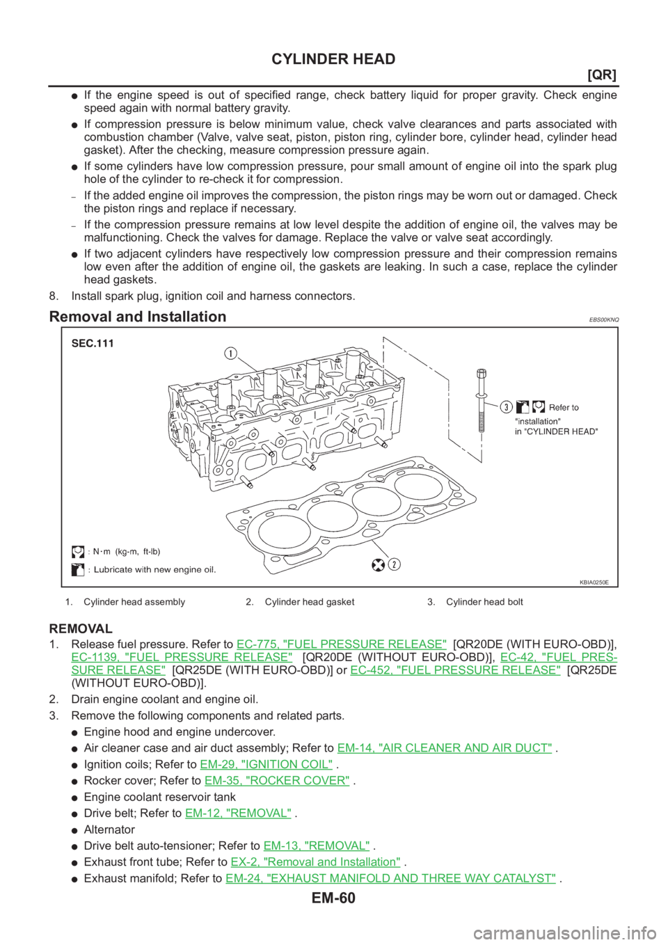
Removal and InstallationEBS00KNQ
REMOVAL
1. Release fuel pressure. Refer to EC-775, "FUEL PRESSURE RELEASE" [QR20DE (WITH EURO-OBD)],
EC-1139, "
FUEL PRESSURE RELEASE" [QR20DE (WITHOUT EURO-OBD)], EC-42, "FUEL PRES-
SURE RELEASE" [QR25DE (WITH EURO-OBD)] or EC-452, "FUEL PRESSURE RELEASE" [QR25DE
(WITHOUT EURO-OBD)].
2. Drain engine coolant and engine oil.
3. Remove the following components and related parts.
●Engine hood and engine undercover.
●Air cleaner case and air duct assembly; Refer to EM-14, "AIR CLEANER AND AIR DUCT" .
●Ignition coils; Refer to EM-29, "IGNITION COIL" .
●Rocker cover; Refer to EM-35, "ROCKER COVER" .
●Engine coolant reservoir tank
●Drive belt; Refer to EM-12, "REMOVAL" .
●Alternator
●Drive belt auto-tensioner; Refer to EM-13, "REMOVAL" .
●Exhaust front tube; Refer to EX-2, "Removal and Installation" .
●Exhaust manifold; Refer to EM-24, "EXHAUST MANIFOLD AND THREE WAY CATALYST" .
KBIA0250E
1. Cylinder head assembly 2. Cylinder head gasket 3. Cylinder head bolt
Page 111 of 3833
CYLINDER HEAD
EM-61
[QR]
C
D
E
F
G
H
I
J
K
L
MA
EM
●Intake manifold collector, intake manifold and fuel tube assembly; Refer to EM-16, "INTAKE MANI-
FOLD" .
●Water control valve and housing; Refer to CO-20, "THERMOSTAT AND WATER CONTROL VALVE" .
4. Remove front cover and timing chain. Refer to EM-37, "
TIMING CHAIN" .
5. Remove camshaft. Refer to EM-46, "
CAMSHAFT" .
6. Securely support bottom of cylinder block with a jack or equivalent tool, and remove the hoist that was
supporting it.
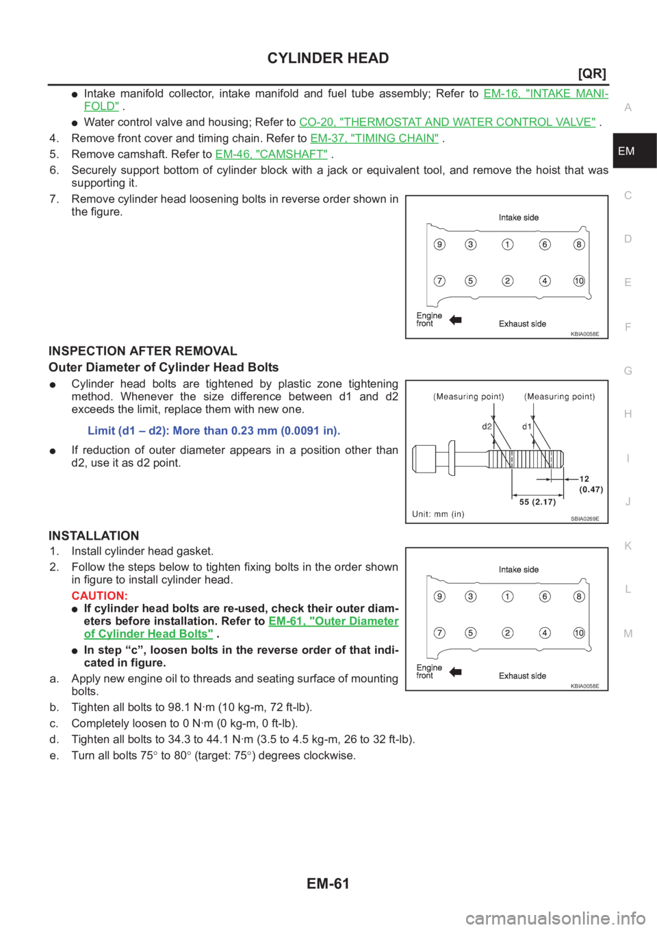
7. Remove cylinder head loosening bolts in reverse order shown in
the figure.
INSPECTION AFTER REMOVAL
Outer Diameter of Cylinder Head Bolts
●Cylinder head bolts are tightened by plastic zone tightening
method. Whenever the size difference between d1 and d2
exceeds the limit, replace them with new one.
●If reduction of outer diameter appears in a position other than
d2, use it as d2 point.
INSTALLATION
1. Install cylinder head gasket.
2. Follow the steps below to tighten fixing bolts in the order shown
in figure to install cylinder head.
CAUTION:
●If cylinder head bolts are re-used, check their outer diam-
eters before installation. Refer to EM-61, "
Outer Diameter
of Cylinder Head Bolts" .
●In step “c”, loosen bolts in the reverse order of that indi-
cated in figure.
a. Apply new engine oil to threads and seating surface of mounting
bolts.
b. Tighten all bolts to 98.1 N·m (10 kg-m, 72 ft-lb).
c. Completely loosen to 0 N·m (0 kg-m, 0 ft-lb).
d. Tighten all bolts to 34.3 to 44.1 N·m (3.5 to 4.5 kg-m, 26 to 32 ft-lb).
e. Turn all bolts 75° to 80° (target: 75°) degrees clockwise.
KBIA0058E
Limit (d1 – d2): More than 0.23 mm (0.0091 in).
SBIA0269E
KBIA0058E
Page 112 of 3833
EM-62
[QR]
CYLINDER HEAD
f. Turn all bolts 75° to 80° (target: 75°) degrees clockwise again.
CAUTION:
Check and confirm the tightening angle by using angle
wrench or protractor. Avoid judgment by visual inspection
without the tool.
3. Install followings in reverse order of removal.
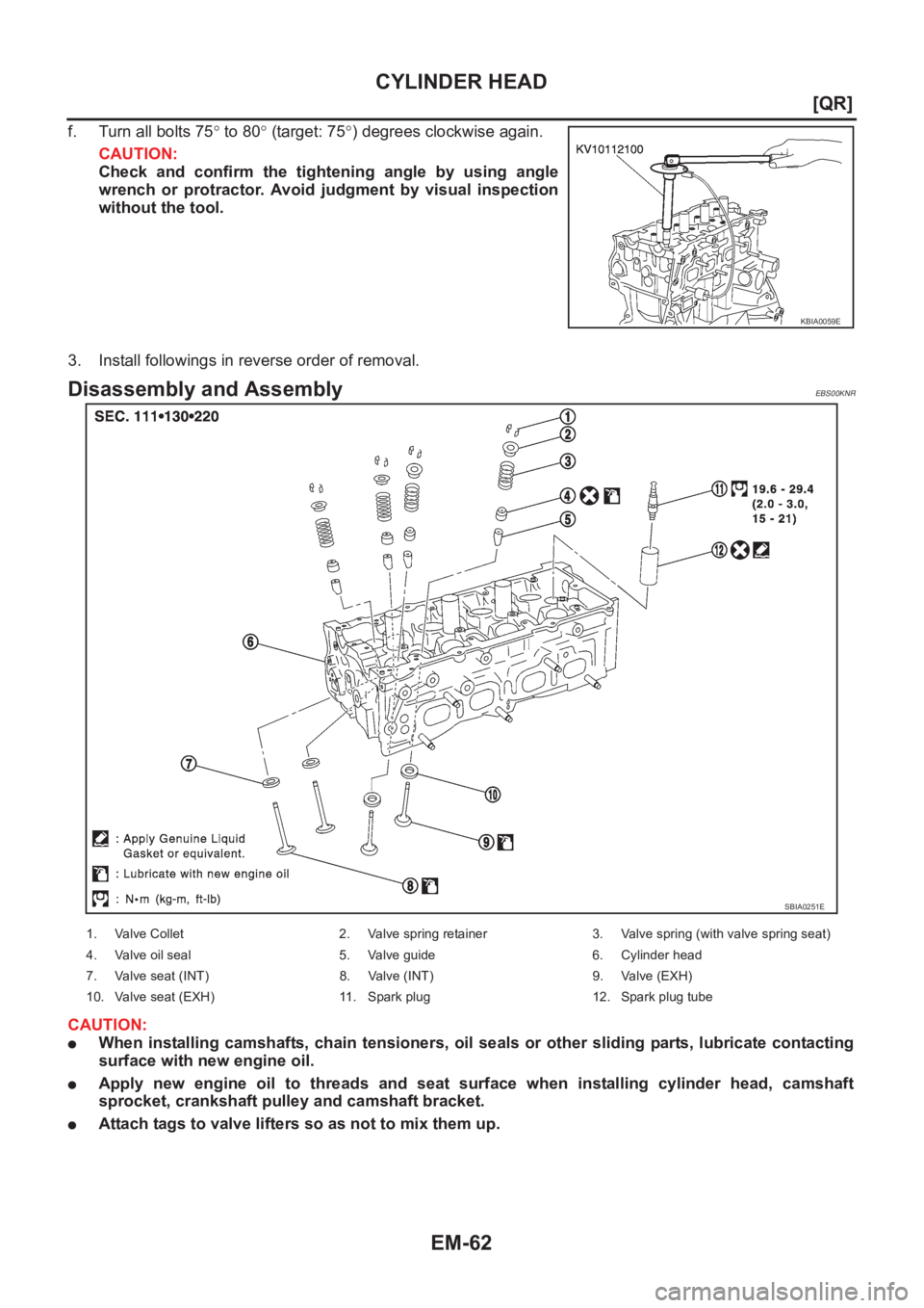
Disassembly and AssemblyEBS00KNR
CAUTION:
●When installing camshafts, chain tensioners, oil seals or other sliding parts, lubricate contacting
surface with new engine oil.
●Apply new engine oil to threads and seat surface when installing cylinder head, camshaft
sprocket, crankshaft pulley and camshaft bracket.
●Attach tags to valve lifters so as not to mix them up.
KBIA0059E
SBIA0251E
1. Valve Collet 2. Valve spring retainer 3. Valve spring (with valve spring seat)
4. Valve oil seal 5. Valve guide 6. Cylinder head
7. Valve seat (INT) 8. Valve (INT) 9. Valve (EXH)
10. Valve seat (EXH) 11. Spark plug 12. Spark plug tube
Page 114 of 3833
EM-64
[QR]
CYLINDER HEAD
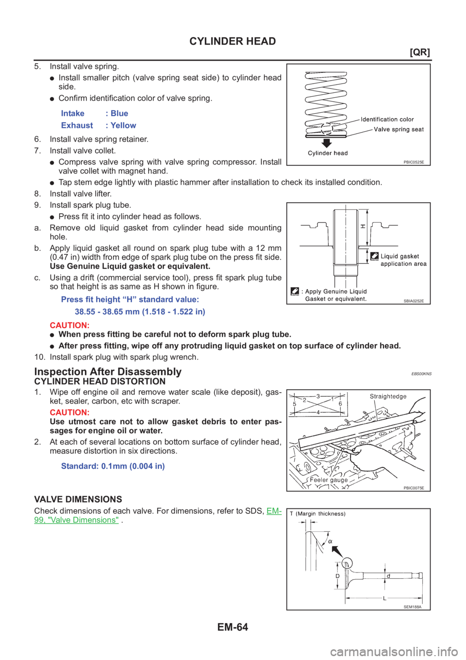
5. Install valve spring.
●Install smaller pitch (valve spring seat side) to cylinder head
side.
●Confirm identification color of valve spring.
6. Install valve spring retainer.
7. Install valve collet.
●Compress valve spring with valve spring compressor. Install
valve collet with magnet hand.
●Tap stem edge lightly with plastic hammer after installation to check its installed condition.
8. Install valve lifter.
9. Install spark plug tube.
●Press fit it into cylinder head as follows.
a. Remove old liquid gasket from cylinder head side mounting
hole.
b. Apply liquid gasket all round on spark plug tube with a 12 mm
(0.47 in) width from edge of spark plug tube on the press fit side.
Use Genuine Liquid gasket or equivalent.
c. Using a drift (commercial service tool), press fit spark plug tube
so that height is as same as H shown in figure.
CAUTION:
●When press fitting be careful not to deform spark plug tube.
●After press fitting, wipe off any protruding liquid gasket on top surface of cylinder head.
10. Install spark plug with spark plug wrench.
Inspection After DisassemblyEBS00KNS
CYLINDER HEAD DISTORTION
1. Wipe off engine oil and remove water scale (like deposit), gas-
ket, sealer, carbon, etc with scraper.
CAUTION:
Use utmost care not to allow gasket debris to enter pas-
sages for engine oil or water.
2. At each of several locations on bottom surface of cylinder head,
measure distortion in six directions.
VALVE DIMENSIONS
Check dimensions of each valve. For dimensions, refer to SDS, EM-
99, "Valve Dimensions" . Intake : Blue
Exhaust : Yellow
Press fit height “H” standard value:
38.55 - 38.65 mm (1.518 - 1.522 in)
PBIC0525E
SBIA0252E
Standard: 0.1mm (0.004 in)
PBIC0075E
SEM188A
Page 121 of 3833
ENGINE ASSEMBLY
EM-71
[QR]
C
D
E
F
G
H
I
J
K
L
MA
EM
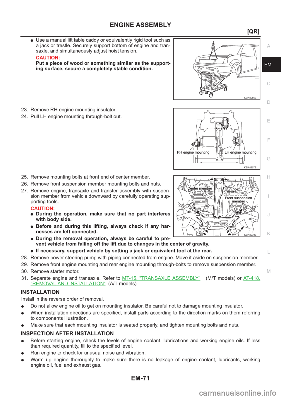
●Use a manual lift table caddy or equivalently rigid tool such as
a jack or trestle. Securely support bottom of engine and tran-
saxle, and simultaneously adjust hoist tension.
CAUTION:
Put a piece of wood or something similar as the support-
ing surface, secure a completely stable condition.
23. Remove RH engine mounting insulator.
24. Pull LH engine mounting through-bolt out.
25. Remove mounting bolts at front end of center member.
26. Remove front suspension member mounting bolts and nuts.
27. Remove engine, transaxle and transfer assembly with suspen-
sion member from vehicle downward by carefully operating sup-
porting tools.
CAUTION:
●During the operation, make sure that no part interferes
with body side.
●Before and during this lifting, always check if any har-
nesses are left connected.
●During the removal operation, always be careful to pre-
vent vehicle from falling off the lift due to changes in the center of gravity.
●If necessary, support vehicle by setting a jack or equivalent tool at the rear.
28. Remove power steering pump with piping connected from engine. Move it aside on suspension member.
29. Remove front engine mounting and rear engine mounting through-bolts to remove suspension member.
30. Remove starter motor.
31. Separate engine and transaxle. Refer to MT-15, "
TRANSAXLE ASSEMBLY" (M/T models) or AT- 4 1 8 ,
"REMOVAL AND INSTALLATION" (A/T models)
INSTALLATION
Install in the reverse order of removal.
●Do not allow engine oil to get on mounting insulator. Be careful not to damage mounting insulator.
●When installation directions are specified, install parts according to the direction marks on them referring
to components illustration.
●Make sure that each mounting insulator is seated properly, and tighten mounting bolts and nuts.
INSPECTION AFTER INSTALLATION
●Before starting engine, check the levels of engine coolant, lubrications and working engine oils. If less
than required quantity, fill to the specified level.
●Run engine to check for unusual noise and vibration.
●Warm up engine thoroughly to make sure there is no leakage of engine coolant, lubricants, working
engine oil, fuel and exhaust gas.
KBIA0256E
KBIA0257E
KBIA0270E
Page 129 of 3833
CYLINDER BLOCK
EM-79
[QR]
C
D
E
F
G
H
I
J
K
L
MA
EM
5. Install the crankshaft to the cylinder block.
●While turning the crankshaft by hand, check that it turns smoothly.
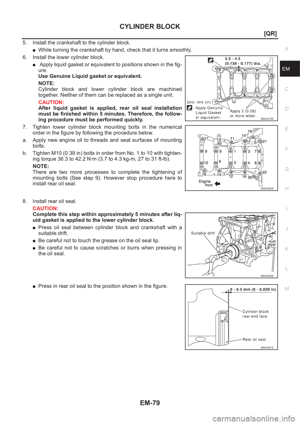
6. Install the lower cylinder block.
● Apply liquid gasket or equivalent to positions shown in the fig-
ure.
Use Genuine Liquid gasket or equivalent.
NOTE:
Cylinder block and lower cylinder block are machined
together. Neither of them can be replaced as a single unit.
CAUTION:
After liquid gasket is applied, rear oil seal installation
must be finished within 5 minutes. Therefore, the follow-
ing procedure must be performed quickly.
7. Tighten lower cylinder block mounting bolts in the numerical
order in the figure by following the procedure below.
a. Apply new engine oil to threads and seat surfaces of mounting
bolts.
b. Tighten M10 (0.39 in) bolts in order from No. 1 to 10 with tighten-
ing torque 36.3 to 42.2 N·m (3.7 to 4.3 kg-m, 27 to 31 ft-lb).
NOTE:
There are two more processes to complete the tightening of
mounting bolts (See step 9). However stop procedure here to
install rear oil seal.
8. Install rear oil seal.
CAUTION:
Complete this step within approximately 5 minutes after liq-
uid gasket is applied to the lower cylinder block.
●Press oil seal between cylinder block and crankshaft with a
suitable drift.
●Be careful not to touch the grease on the oil seal lip.
●Be careful not to cause scratches or burrs when pressing in
the oil seal.
●Press in rear oil seal to the position shown in the figure.
SBIA0279E
KBIA0063E
SBIA0280E
SBIA0281E