clock NISSAN X-TRAIL 2001 Service Owner's Guide
[x] Cancel search | Manufacturer: NISSAN, Model Year: 2001, Model line: X-TRAIL, Model: NISSAN X-TRAIL 2001Pages: 3833, PDF Size: 39.49 MB
Page 3324 of 3833
ATC-48
TROUBLE DIAGNOSIS
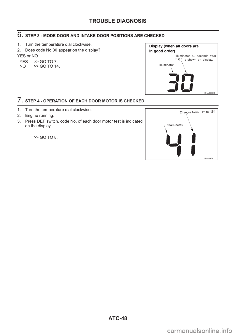
6. STEP 3 - MODE DOOR AND INTAKE DOOR POSITIONS ARE CHECKED
1. Turn the temperature dial clockwise.
2. Does code No.30 appear on the display?
YES or NO
YES >> GO TO 7.
NO >> GO TO 14.
7. STEP 4 - OPERATION OF EACH DOOR MOTOR IS CHECKED
1. Turn the temperature dial clockwise.
2. Engine running.
3. Press DEF switch, code No. of each door motor test is indicated
on the display.
>> GO TO 8.
RHA869DD
RHA495A
Page 3325 of 3833
TROUBLE DIAGNOSIS
ATC-49
C
D
E
F
G
H
I
K
L
MA
B
AT C
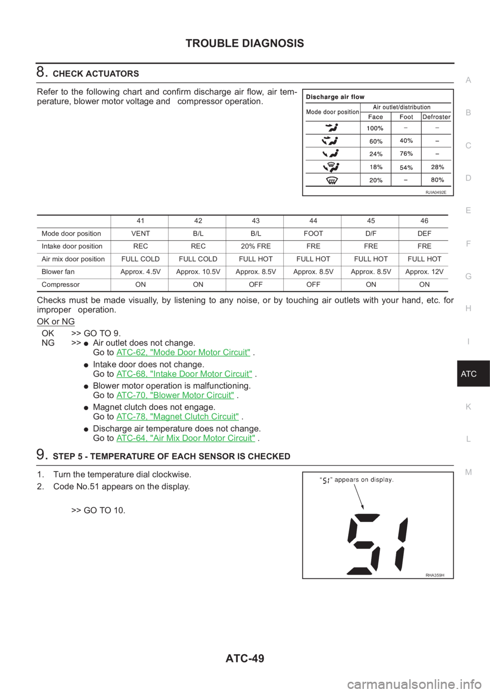
8.CHECK ACTUATORS
Refer to the following chart and confirm discharge air flow, air tem-
perature, blower motor voltage and compressor operation.
Checks must be made visually, by listening to any noise, or by touching air outlets with your hand, etc. for
improper operation.
OK or NG
OK >> GO TO 9.
NG >>
●Air outlet does not change.
Go to ATC-62, "
Mode Door Motor Circuit" .
●Intake door does not change.
Go to ATC-68, "
Intake Door Motor Circuit" .
●Blower motor operation is malfunctioning.
Go to ATC-70, "
Blower Motor Circuit" .
●Magnet clutch does not engage.
Go to ATC-78, "
Magnet Clutch Circuit" .
●Discharge air temperature does not change.
Go to ATC-64, "
Air Mix Door Motor Circuit" .
9.STEP 5 - TEMPERATURE OF EACH SENSOR IS CHECKED
1. Turn the temperature dial clockwise.
2. Code No.51 appears on the display.
>> GO TO 10.
RJIA0492E
41 42 43 44 45 46
Mode door position VENT B/L B/L FOOT D/F DEF
Intake door position REC REC 20% FRE FRE FRE FRE
Air mix door position FULL COLD FULL COLD FULL HOT FULL HOT FULL HOTFULL HOT
Blower fan Approx. 4.5V Approx. 10.5V Approx. 8.5V Approx. 8.5V Approx. 8.5V Approx. 12V
Compressor ON ON OFF OFF ON ON
RHA359H
Page 3413 of 3833

REFRIGERANT LINES
ATC-137
C
D
E
F
G
H
I
K
L
MA
B
AT C
2. When removing center bolt, hold clutch disc with clutch disc
wrench.
3. Remove the drive plate using the clutch disc puller.
4. Insert holder's three pins into the drive plate. Rotate the holder
clockwise to hook it onto the plate.
5. Tighten the center bolt to remove the drive plate.
6. While tightening the center bolt, insert a screwdriver between
two of the pins (as shown in the figure) to prevent rotation.
7. After removing the drive plate, remove the shims from either the
drive shaft or the drive plate.
8. Remove the snap ring using external snap ring pliers.
9. Remove the pulley assembly with the puller using a commer-
cially available pulley puller. (Position the center of the puller on
the end of the drive shaft)
For pressed pulleys:
To prevent deformation of the pulley groove, the puller claws
should be hooked under (not into) the pulley groove.
For machine lathed pulleys:
Align the pulley puller groove with the pulley groove, and then
remove the pulley assembly.
10. Remove the field coil harness clip using a screwdriver.
11. Then remove the three field coil fixing screws and remove the
field coil.
SHA097EA
ZHA093H
RHA072C
SHA099EA
RHA074C
Page 3426 of 3833
ATC-150
SERVICE DATA AND SPECIFICATIONS (SDS)
SERVICE DATA AND SPECIFICATIONS (SDS)
PFP:00030
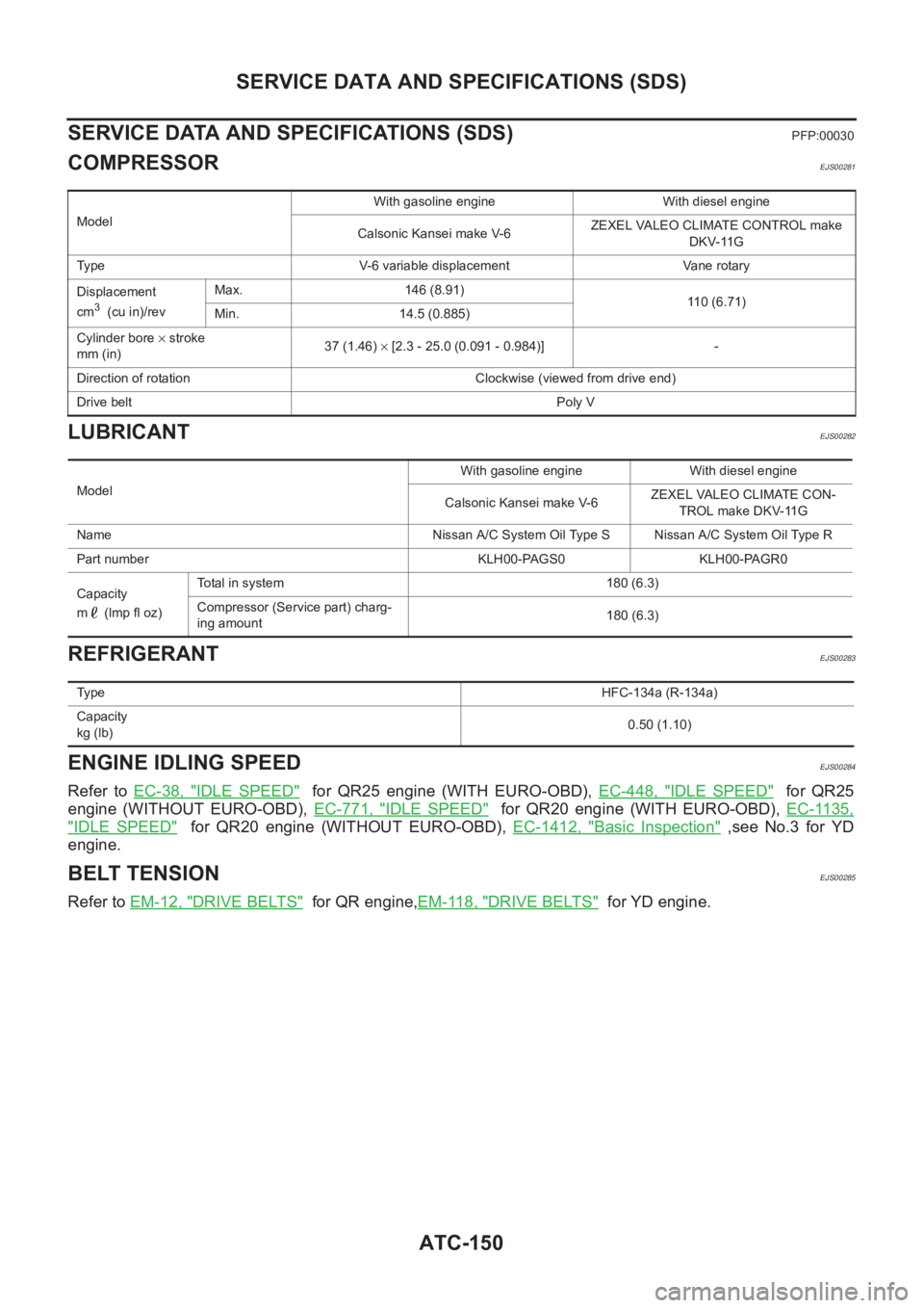
COMPRESSOREJS00281
LUBRICANTEJS00282
REFRIGERANTEJS00283
ENGINE IDLING SPEEDEJS00284
Refer to EC-38, "IDLE SPEED" for QR25 engine (WITH EURO-OBD), EC-448, "IDLE SPEED" for QR25
engine (WITHOUT EURO-OBD), EC-771, "
IDLE SPEED" for QR20 engine (WITH EURO-OBD), EC-1135,
"IDLE SPEED" for QR20 engine (WITHOUT EURO-OBD), EC-1412, "Basic Inspection" ,see No.3 for YD
engine.
BELT TENSIONEJS00285
Refer to EM-12, "DRIVE BELTS" for QR engine,EM-118, "DRIVE BELTS" for YD engine.
ModelWith gasoline engine With diesel engine
Calsonic Kansei make V-6ZEXEL VALEO CLIMATE CONTROL make
DKV-11G
Type V-6 variable displacement Vane rotary
Displacement
cm
3 (cu in)/revMax. 146 (8.91)
110 (6.71)
Min. 14.5 (0.885)
Cylinder bore × stroke
mm (in)37 (1.46) × [2.3 - 25.0 (0.091 - 0.984)] -
Direction of rotation Clockwise (viewed from drive end)
Drive beltPoly V
ModelWith gasoline engine With diesel engine
Calsonic Kansei make V-6ZEXEL VALEO CLIMATE CON-
TROL make DKV-11G
Name Nissan A/C System Oil Type S Nissan A/C System Oil Type R
Part number KLH00-PAGS0 KLH00-PAGR0
Capacity
m (lmp fl oz)Total in system 180 (6.3)
Compressor (Service part) charg-
ing amount180 (6.3)
Ty p eHFC-134a (R-134a)
Capacity
kg (lb)0.50 (1.10)
Page 3474 of 3833
SC-18
CHARGING SYSTEM
REAR BEARING
CAUTION:
●Do not reuse rear bearing after removal. Replace with a new one.
●Do not lubricate rear bearing outer race.
InspectionEKS0031D
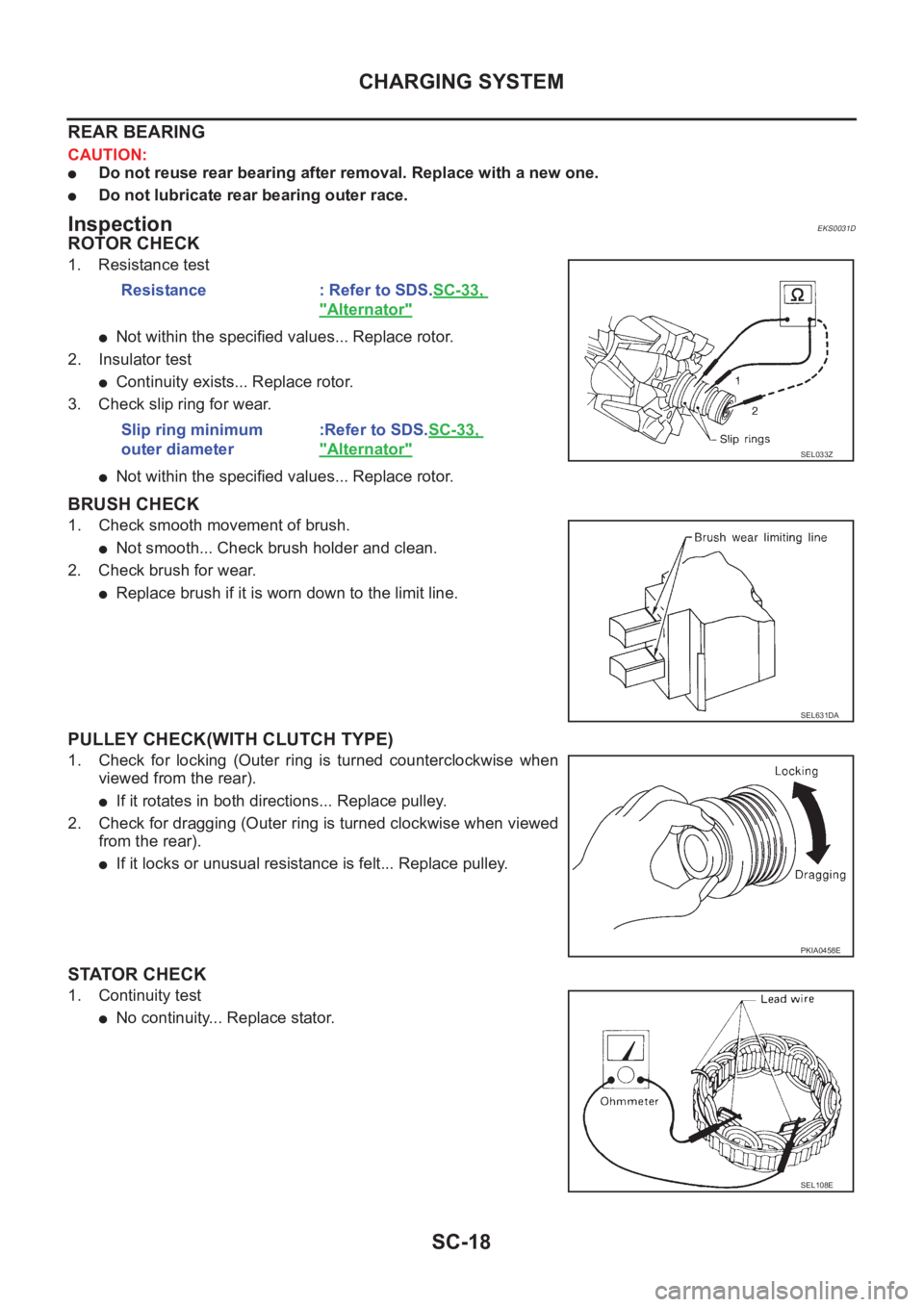
ROTOR CHECK
1. Resistance test
●Not within the specified values... Replace rotor.
2. Insulator test
●Continuity exists... Replace rotor.
3. Check slip ring for wear.
●Not within the specified values... Replace rotor.
BRUSH CHECK
1. Check smooth movement of brush.
●Not smooth... Check brush holder and clean.
2. Check brush for wear.
●Replace brush if it is worn down to the limit line.
PULLEY CHECK(WITH CLUTCH TYPE)
1. Check for locking (Outer ring is turned counterclockwise when
viewed from the rear).
●If it rotates in both directions... Replace pulley.
2. Check for dragging (Outer ring is turned clockwise when viewed
from the rear).
●If it locks or unusual resistance is felt... Replace pulley.
STATOR CHECK
1. Continuity test
●No continuity... Replace stator.Resistance : Refer to SDS.SC-33,
"Alternator"
Slip ring minimum
outer diameter:Refer to SDS.SC-33,
"Alternator"SEL033Z
SEL631DA
PKIA0458E
SEL108E
Page 3498 of 3833

LT-8
HEADLAMP
Bulb Replacement
EKS003CH
HEAD LAMP
1. Disconnect connector of headlamp.
2. Remove rubber cap.
3. Unlock retaining spring, then remove bulb.
CLEARANCE LAMP
1. Turn the RH bulbsocket clockwise and unlock it.
Turn the LH bulbsocket counterclockwise and unlock it.
2. Remove the bulb from its socket.
CAUTION:
●Do not touch the glass of bulb directly by hand. Keep grease and other oily matters away from it.
Do not touch bulb by hand while it is lit or right after being turned off. Burning may result.
●Do not leave bulb out of headlamp reflector for a long time because dust, moisture smoke, etc.
may affect the performance of headlamp. When replacing bulb, be sure to replace it with new one.
●When bulb is installed, be sure to lock rubber cap to ensure watertightness.
Removal and Installation EKS003CI
REMOVAL
1. Remove the front turn signal lamps. Refer toLT- 2 2 , "Removal
and Installation for Front Turn Signal Lamp"
2. Disconnect connector of headlamp and clearance lamp.
3. Remove the front grille. Refer to EI-11, "
FRONT GRILLE" in
"EXTERIOR & INTERIOR (EI)" section.
4. Remove the headlamp mounting bolts.
5. Pull the headlamp toward the front of the vehicle.
INSTALLATION
●Install in the reverse order of removal, taking care of the following points.
Headlamp mounting boltsHeadlamp (High/Low) : 12V 60/55 W(H4)
SKIA0073E
Clearance lamp : 12V 5W
SKIA0050E
Tightening torque : 4.5 - 6.4 N-m (0.45 - 0.65 kg-m, 39 - 56 in-lb)
Page 3512 of 3833

LT-22
TURN SIGNAL AND HAZARD WARNING LAMPS
Bulb Replacement
EKS0034D
FRONT TURN SIGNAL LAMP
1. Remove the front turn signal lamp. Refer toLT- 2 2 , "Removal and
Installation for Front Turn Signal Lamp"
2. Turn the bulb socket counterclockwise and unlock it.
3. Remove the bulb from its socket.
SIDE TURN SIGNAL LAMP
1. Remove side turn signal lamp. Refer toLT- 2 3 , "Removal and
Installation for Side Turn Signal Lamp"
2. Turn the bulb socket counterclockwise and unlock it.
3. Remove the bulb from its socket.
REAR TURN SIGNAL LAMP
Refer to LT-42, "REAR COMBINATION LAMP"
Removal and Installation for Front Turn Signal LampEKS003BH
REMOVAL
1. Press the upper pawl to remove front turn signal lamp toward
the front of the vehicle.
2. Disconnect front turn signal lamp connector.
INSTALLATION
1. Connect front turn signal lamp connector.
2. Insert the pawl into head lamp hole, and install front turn signal lamp.
SKIA0053E
Front turn signal lamp : 12V 21W (amber)
PKIA0468E
Side turn signal lamp : 12V 5W
SKIA0054E
Page 3517 of 3833

STOP LAMP
LT-27
C
D
E
F
G
H
I
J
L
MA
B
LT
Bulb ReplacementEKS0034K
STOP LAMP
Refer to LT- 4 2 , "REAR COMBINATION LAMP"
HIGH-MOUNTED STOP LAMP
1. Remove the high-mounted stop lamp cover. Refer toLT- 2 7 ,
"HIGH-MOUNTED STOP LAMP" .
2. Turn the high-mounted stop lamp bulb socket counterclockwise
and unlock it.
3. Remove the bulb.
Removal and InstallationEKS0034L
STOP LAMP
Refer toLT-42, "REAR COMBINATION LAMP"
HIGH-MOUNTED STOP LAMP
1. Pull the edge of the cover (A in the figure below) to each side in
turn downward until the pawls inside the cover are released.
2. Pull down the cover toward under the vehicle.
3. Remove the high-mounted stop lamp mounting bolts.
4. Disconnect the high-mounted stop lamp connector and remove
from the vehicle.High-mounted Stop Lamp : 12V 5W
PKIA0496E
PKIA0497E
PKIA0498E
Page 3526 of 3833

LT-36
FRONT FOG LAMP
Bulb Replacement
EKS003DI
1. Remove fog lamp. Refer toLT-36, "Removal and Installation" .
2. Turn plastic cap counter clockwise then remove it.
3. Unlock retaining spring, then remove bulb.
CAUTION:
●Do not touch the glass of bulb directly by hand. Keep
grease and other oily matters away from it. Do not touch
bulb by hand while it is lit or right after being turned off.
Burning may result.
●Do not leave bulb out of headlamp reflector for a long time
because dust, moisture smoke, etc. May affect the performance of headlamp. When replacing
bulb, be sure to replace it with new one.
●When bulb is installed, be sure to lock plastic cap to ensure watertightness.
Removal and Installation EKS003DJ
REMOVAL
1. Remove fender protector. Refer toEI-13, "FENDER PROTECTOR"
2. Disconnect fog lamp connector.
3. Remove fog lamp mounting bolt.
4. Pull out fog lamp from vehicle and disconnect connector.
INSTALLATION
●Install fog lamp in the reverse order of removal, observing the tightening torque shown below.
Fog lamp mounting boltFront fog lamp :12 V 55 W (H3)
PKIA0546E
PKIA0547E
Tightening torque :3.3 -7.7 N-m (0.33 - 0.79 kg-m, 29 - 69 in-lb)
Page 3529 of 3833

REAR FOG LAMP
LT-39
C
D
E
F
G
H
I
J
L
MA
B
LT
Bulb ReplacementEKS0015L
1. Remove rear fog lamp. Refer toLT- 3 9 , "Removal and Installa-
tion" .
2. Turn bulb socket counterclockwise and unlock it.
3. Remove bulb.
Removal and InstallationEKS0015M
REMOVAL
1. Remove rear fog lamp mounting screws (2).
2. Take out rear fog lamp from bumper, then disconnect connector.
INSTALLATION
Install in the reverse order of removal, paying attention to the following. Rear fog lamp : 12V 21W
SKIA0052E
SKIA0090E
Rear fog lamp mounting screws
Tightening torque : 0.98 - 1.86 N-m (0.10 - 0.18 kg-m, 9-16 in-lb)