fuel pressure NISSAN X-TRAIL 2001 Service Repair Manual
[x] Cancel search | Manufacturer: NISSAN, Model Year: 2001, Model line: X-TRAIL, Model: NISSAN X-TRAIL 2001Pages: 3833, PDF Size: 39.49 MB
Page 8 of 3833

GI-6
PRECAUTIONS
CAUTION:
●Do not use home heating oil, gasoline or other alternate fuels in your diesel engine. The use of
those can cause engine damage.
●Do not use summer fuel at temperatures below –7°C (20°F). The cold temperatures will cause wax
to form in the fuel. As a result, it may prevent the engine from running smoothly.
●Do not add gasoline or other alternate fuels to diesel fuel.
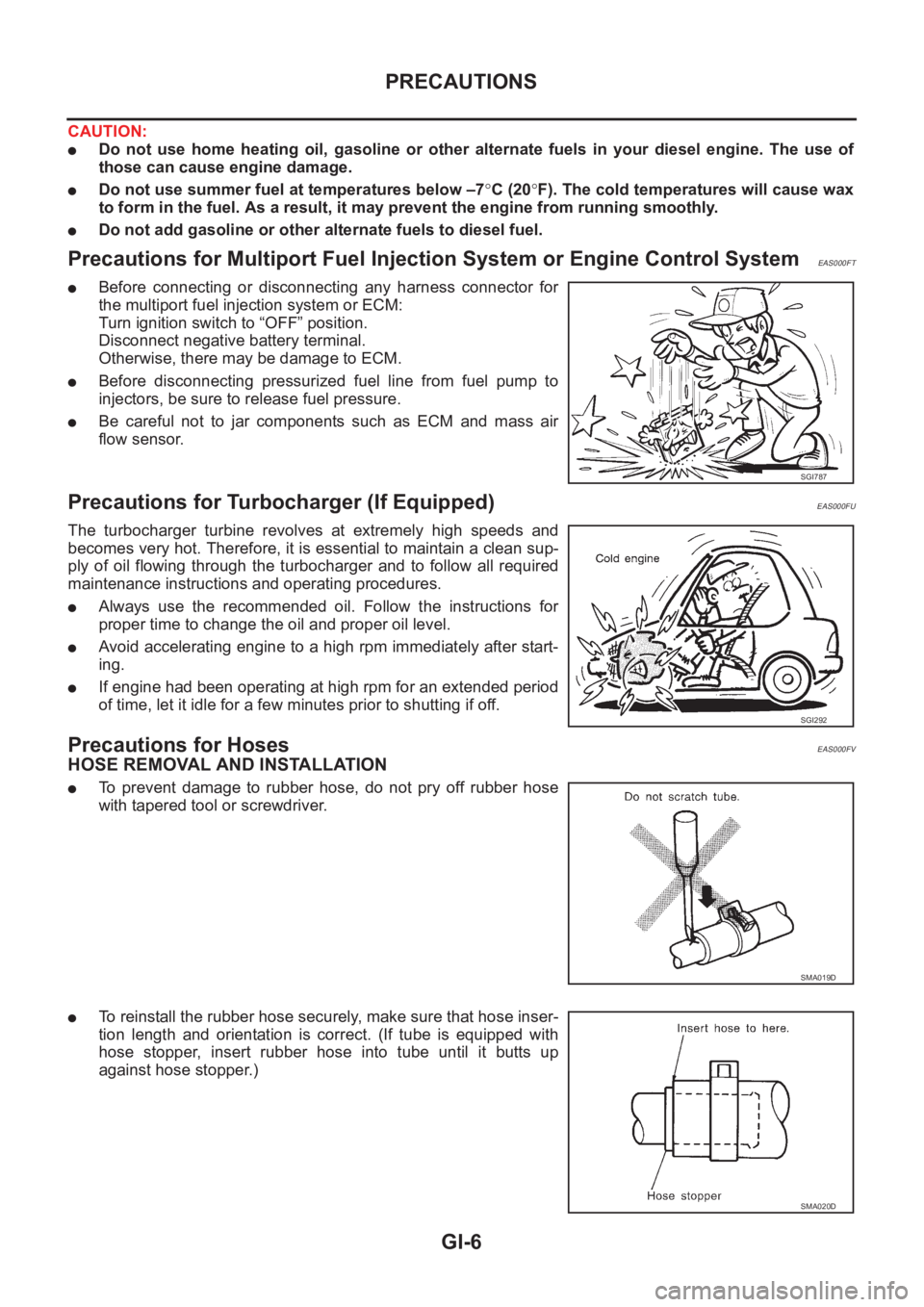
Precautions for Multiport Fuel Injection System or Engine Control SystemEAS000FT
●Before connecting or disconnecting any harness connector for
the multiport fuel injection system or ECM:
Turn ignition switch to “OFF” position.
Disconnect negative battery terminal.
Otherwise, there may be damage to ECM.
●Before disconnecting pressurized fuel line from fuel pump to
injectors, be sure to release fuel pressure.
●Be careful not to jar components such as ECM and mass air
flow sensor.
Precautions for Turbocharger (If Equipped)EAS000FU
The turbocharger turbine revolves at extremely high speeds and
becomes very hot. Therefore, it is essential to maintain a clean sup-
ply of oil flowing through the turbocharger and to follow all required
maintenance instructions and operating procedures.
●Always use the recommended oil. Follow the instructions for
proper time to change the oil and proper oil level.
●Avoid accelerating engine to a high rpm immediately after start-
ing.
●If engine had been operating at high rpm for an extended period
of time, let it idle for a few minutes prior to shutting if off.
Precautions for HosesEAS000FV
HOSE REMOVAL AND INSTALLATION
●To prevent damage to rubber hose, do not pry off rubber hose
with tapered tool or screwdriver.
●To reinstall the rubber hose securely, make sure that hose inser-
tion length and orientation is correct. (If tube is equipped with
hose stopper, insert rubber hose into tube until it butts up
against hose stopper.)
SGI787
SGI292
SMA019D
SMA020D
Page 47 of 3833

TERMINOLOGY
GI-45
C
D
E
F
G
H
I
J
K
L
MB
GI
TERMINOLOGYPFP:00011
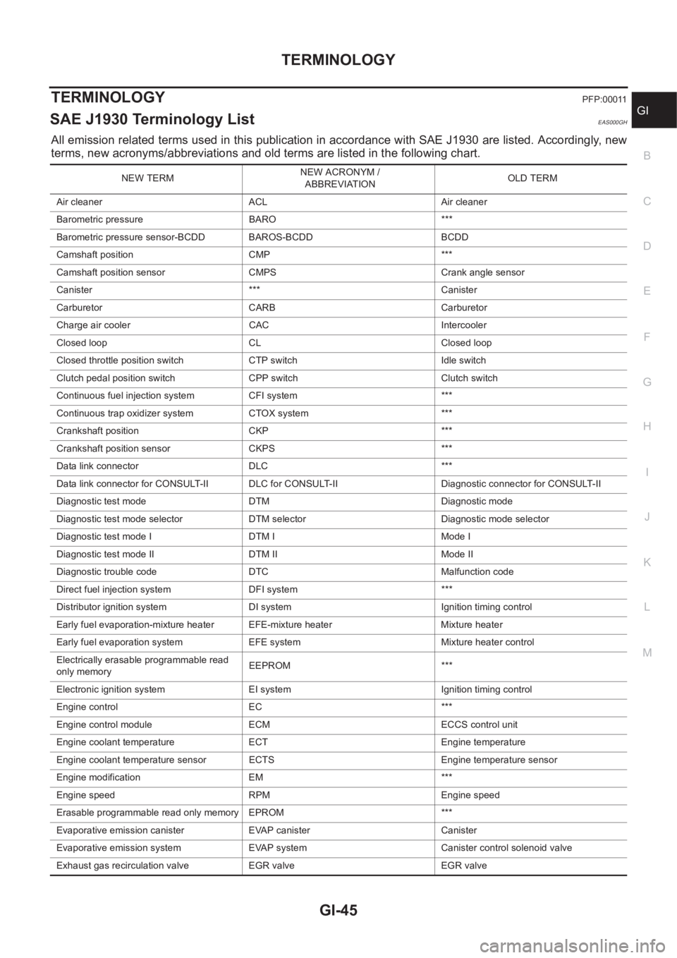
SAE J1930 Terminology List EAS000GH
All emission related terms used in this publication in accordance with SAE J1930 are listed. Accordingly, new
terms, new acronyms/abbreviations and old terms are listed in the following chart.
NEW TERMNEW ACRONYM /
ABBREVIATIONOLD TERM
Air cleaner ACL Air cleaner
Barometric pressure BARO ***
Barometric pressure sensor-BCDD BAROS-BCDD BCDD
Camshaft position CMP ***
Camshaft position sensor CMPS Crank angle sensor
Canister *** Canister
Carburetor CARB Carburetor
Charge air cooler CAC Intercooler
Closed loop CL Closed loop
Closed throttle position switch CTP switch Idle switch
Clutch pedal position switch CPP switch Clutch switch
Continuous fuel injection system CFI system ***
Continuous trap oxidizer system CTOX system ***
Crankshaft position CKP ***
Crankshaft position sensor CKPS ***
Data link connector DLC ***
Data link connector for CONSULT-II DLC for CONSULT-II Diagnostic connector for CONSULT-II
Diagnostic test mode DTM Diagnostic mode
Diagnostic test mode selector DTM selector Diagnostic mode selector
Diagnostic test mode I DTM I Mode I
Diagnostic test mode II DTM II Mode II
Diagnostic trouble code DTC Malfunction code
Direct fuel injection system DFI system ***
Distributor ignition system DI system Ignition timing control
Early fuel evaporation-mixture heater EFE-mixture heater Mixture heater
Early fuel evaporation system EFE system Mixture heater control
Electrically erasable programmable read
only memoryEEPROM ***
Electronic ignition system EI system Ignition timing control
Engine control EC ***
Engine control module ECM ECCS control unit
Engine coolant temperature ECT Engine temperature
Engine coolant temperature sensor ECTS Engine temperature sensor
Engine modification EM ***
Engine speed RPM Engine speed
Erasable programmable read only memory EPROM ***
Evaporative emission canister EVAP canister Canister
Evaporative emission system EVAP system Canister control solenoid valve
Exhaust gas recirculation valve EGR valve EGR valve
Page 48 of 3833

GI-46
TERMINOLOGY
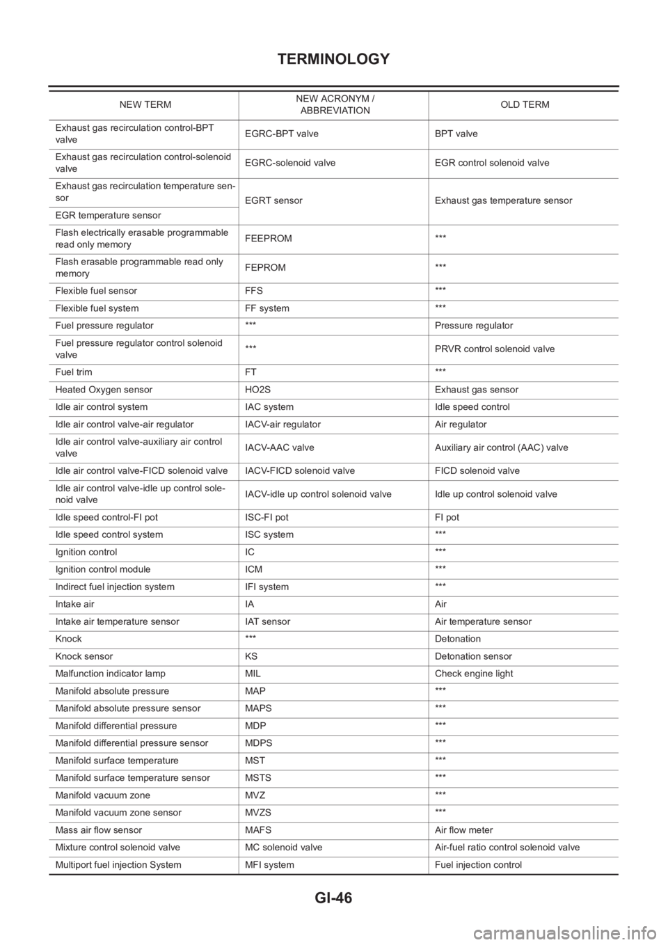
Exhaust gas recirculation control-BPT
valveEGRC-BPT valve BPT valve
Exhaust gas recirculation control-solenoid
valveEGRC-solenoid valve EGR control solenoid valve
Exhaust gas recirculation temperature sen-
sor
EGRT sensor Exhaust gas temperature sensor
EGR temperature sensor
Flash electrically erasable programmable
read only memoryFEEPROM ***
Flash erasable programmable read only
memoryFEPROM ***
Flexible fuel sensor FFS ***
Flexible fuel system FF system ***
Fuel pressure regulator *** Pressure regulator
Fuel pressure regulator control solenoid
valve*** PRVR control solenoid valve
Fuel trim FT ***
Heated Oxygen sensor HO2S Exhaust gas sensor
Idle air control system IAC system Idle speed control
Idle air control valve-air regulator IACV-air regulator Air regulator
Idle air control valve-auxiliary air control
valveIACV-AAC valve Auxiliary air control (AAC) valve
Idle air control valve-FICD solenoid valve IACV-FICD solenoid valve FICD solenoid valve
Idle air control valve-idle up control sole-
noid valveIACV-idle up control solenoid valve Idle up control solenoid valve
Idle speed control-FI pot ISC-FI pot FI pot
Idle speed control system ISC system ***
Ignition control IC ***
Ignition control module ICM ***
Indirect fuel injection system IFI system ***
Intake air IA Air
Intake air temperature sensor IAT sensor Air temperature sensor
Knock *** Detonation
Knock sensor KS Detonation sensor
Malfunction indicator lamp MIL Check engine light
Manifold absolute pressure MAP ***
Manifold absolute pressure sensor MAPS ***
Manifold differential pressure MDP ***
Manifold differential pressure sensor MDPS ***
Manifold surface temperature MST ***
Manifold surface temperature sensor MSTS ***
Manifold vacuum zone MVZ ***
Manifold vacuum zone sensor MVZS ***
Mass air flow sensor MAFS Air flow meter
Mixture control solenoid valve MC solenoid valve Air-fuel ratio control solenoid valve
Multiport fuel injection System MFI system Fuel injection controlNEW TERMNEW ACRONYM /
ABBREVIATIONOLD TERM
Page 52 of 3833

EM-2
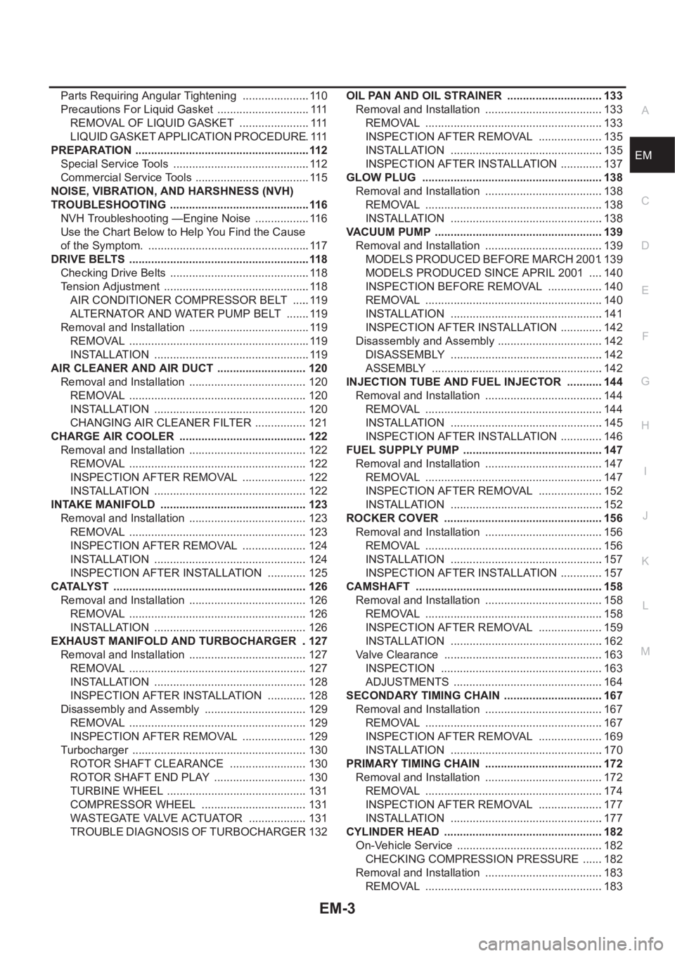
TIMING CHAIN .......................................................... 37
Removal and Installation ........................................ 37
REMOVAL ........................................................... 38
INSPECTION AFTER REMOVAL ........................ 41
INSTALLATION .................................................... 41
CAMSHAFT ............................................................... 46
Removal and Installation ........................................ 46
REMOVAL ........................................................... 46
INSTALLATION .................................................... 48
INSPECTION AFTER REMOVAL ........................ 51
Valve Clearance ...................................................... 53
INSPECTION ....................................................... 53
ADJUSTMENT .................................................... 54
OIL SEAL .................................................................. 56
Removal and Installation of Valve Oil Seal ............. 56
REMOVAL ........................................................... 56
INSTALLATION .................................................... 56
Removal and Installation of Front Oil Seal ............. 56
REMOVAL ........................................................... 56
INSTALLATION .................................................... 57
Removal and Installation of Rear Oil Seal .............. 57
REMOVAL ........................................................... 57
INSTALLATION .................................................... 57
CYLINDER HEAD .................................................. ... 59
On-Vehicle Service ................................................. 59
CHECKING COMPRESSION PRESSURE ......... 59
Removal and Installation ........................................ 60
REMOVAL ........................................................... 60
INSPECTION AFTER REMOVAL ........................ 61
INSTALLATION .................................................... 61
Disassembly and Assembly .................................... 62
DISASSEMBLY ................................................... 63
ASSEMBLY ......................................................... 63
Inspection After Disassembly ................................. 64
CYLINDER HEAD DISTORTION ........................ 64
VALVE DIMENSIONS .......................................... 64
VALVE GUIDE CLEARANCE .............................. 65
VALVE GUIDE REPLACEMENT ......................... 65
VALVE SEAT CONTACT ..................................... 66
VALVE SEAT REPLACEMENT ........................... 66
VALVE SPRING SQUARENESS ......................... 67
VALVE SPRING DIMENSIONS AND VALVE
SPRING PRESSURE LOAD ............................... 68
ENGINE ASSEMBLY ................................................ 69
Removal and Installation ........................................ 69
REMOVAL .......................................................
.... 69
INSTALLATION .................................................... 71
INSPECTION AFTER INSTALLATION ................ 71
CYLINDER BLOCK ................................................... 73
Disassembly and Assembly .................................... 73
DISASSEMBLY ................................................... 74
ASSEMBLY ......................................................... 78
How to Select Piston and Bearing .......................... 82
DESCRIPTION .................................................... 82
HOW TO SELECT PISTON ................................. 83
HOW TO SELECT CONNECTING ROD BEAR-
ING ...................................................................... 83HOW TO SELECT MAIN BEARING .................... 85
Inspection After Disassembly .................................. 88
CRANKSHAFT END PLAY .................................. 88
CONNECTING ROD SIDE CLEARANCE ........... 89
PISTON AND PISTON PIN CLEARANCE ........... 89
PISTON RING SIDE CLEARANCE ..................... 90
PISTON RING END GAP .................................... 90
CONNECTING ROD BEND AND TORSION ....... 91
CONNECTING ROD BEARING (BIG END) ........ 91
CONNECTING ROD BUSHING OIL CLEAR-
ANCE (SMALL END) ........................................... 91
CYLINDER BLOCK DISTORTION ...................... 92
INNER DIAMETER OF MAIN BEARING HOUS-
ING ....................................................................... 93
PISTON TO CYLINDER BORE CLEARANCE .... 93
OUTER DIAMETER OF CRANKSHAFT JOUR-
NAL ...................................................................... 94
OUTER DIAMETER OF CRANKSHAFT PIN ...... 94
OUT-OF-ROUND AND TAPER OF CRANK-
SHAFT ................................................................. 94
CRANKSHAFT RUNOUT .................................... 95
CONNECTING ROD BEARING OIL CLEAR-
ANCE ................................................................... 95
MAIN BEARING OIL CLEARANCE ..................... 95
MAIN BEARING CRUSH HEIGHT ...................... 96
OUTER DIAMETER OF LOWER CYLINDER
BLOCK MOUNTING BOLT .................................. 96
OUTER DIAMETER OF CONNECTING ROD
BOLT .................................................................... 96
MOVEMENT AMOUNT OF FLYWHEEL (M/T
MODELS) ............................................................. 97
SERVICE DATA AND SPECIFICATIONS (SDS) ...... 98
Standard and Limit .................................................. 98
GENERAL SPECIFICATIONS ............................. 98
DRIVE BELTS ...................................................... 98
INTAKE MANIFOLD AND EXHAUST MANI-
FOLD ................................................................... 98
SPARK PLUG ...................................................... 98
CYLINDER HEAD ................................................ 98
VALVE .................................................................. 99
CAMSHAFT AND CAMSHAFT BEARING .........102
CYLINDER BLOCK ............................................102
PISTON, PISTON RING AND PISTON PIN .....
.103
CONNECTING ROD ..........................................104
CRANKSHAFT ...................................................105
MAIN BEARING .................................................106
CONNECTING ROD BEARING .........................107
Tightening Torque .................................................108
YD22DDTi
PRECAUTIONS .......................................................110
Precautions for Drain Engine Coolant ...................110
Precautions for Disconnecting Fuel Piping ...........110
Precautions for Removal and Disassembly ..........110
Precautions for Inspection, Repair and Replace-
ment ......................................................................110
Precautions for Assembly and Installation ............110
Page 53 of 3833

EM-3
C
D
E
F
G
H
I
J
K
L
M
EMA Parts Requiring Angular Tightening ...................... 110
Precautions For Liquid Gasket ............................. . 111
REMOVAL OF LIQUID GASKET ...................... . 111
LIQUID GASKET APPLICATION PROCEDURE . . 111
PREPARATION ........................................................112
Special Service Tools ............................................ 112
Commercial Service Tools ..................................... 115
NOISE, VIBRATION, AND HARSHNESS (NVH)
TROUBLESHOOTING .............................................116
NVH Troubleshooting —Engine Noise .................. 116
Use the Chart Below to Help You Find the Cause
of the Symptom. .................................................... 117
DRIVE BELTS ..........................................................118
Checking Drive Belts ............................................. 118
Tension Adjustment ............................................... 118
AIR CONDITIONER COMPRESSOR BELT ...... 119
ALTERNATOR AND WATER PUMP BELT ........ 119
Removal and Installation ....................................... 119
REMOVAL .......................................................... 119
INSTALLATION .................................................. 119
AIR CLEANER AND AIR DUCT ............................. 120
Removal and Installation ...................................... 120
REMOVAL ......................................................... 120
INSTALLATION ................................................. 120
CHANGING AIR CLEANER FILTER ................. 121
CHARGE AIR COOLER ......................................... 122
Removal and Installation ...................................... 122
REMOVAL ......................................................... 122
INSPECTION AFTER REMOVAL ..................... 122
INSTALLATION ................................................. 122
INTAKE MANIFOLD ............................................... 123
Removal and Installation ...................................... 123
REMOVAL ......................................................... 123
INSPECTION AFTER REMOVAL ..................... 124
INSTALLATION ................................................. 124
INSPECTION AFTER INSTALLATION ............. 125
CATALYST .............................................................. 126
Removal and Installation ...................................... 126
REMOVAL ......................................................... 126
INSTALLATION ................................................. 126
EXHAUST MANIFOLD AND TURBOCHARGER .. 127
Removal and Installation ...................................... 127
REMOVAL ......................................................... 127
INSTALLATION ................................................. 128
INSPECTION AFTER INSTALLATION ............. 128
Disassembly and Assembly ................................. 129
REMOVAL ......................................................... 129
INSPECTION AFTER REMOVAL ..................... 129
Turbocharger ........................................................ 130
ROTOR SHAFT CLEARANCE ......................... 130
ROTOR SHAFT END PLAY .............................. 130
TURBINE WHEEL ............................................. 131
COMPRESSOR WHEEL .................................. 131
WASTEGATE VALVE ACTUATOR ................... 131
TROUBLE DIAGNOSIS OF TURBOCHARGER . 132OIL PAN AND OIL STRAINER ...............................133
Removal and Installation ......................................133
REMOVAL .........................................................133
INSPECTION AFTER REMOVAL .....................135
INSTALLATION .................................................135
INSPECTION AFTER INSTALLATION ..............137
GLOW PLUG ..........................................................138
Removal and Installation ......................................138
REMOVAL .........................................................138
INSTALLATION .................................................138
VACUUM PUMP ......................................................139
Removal and Installation ......................................139
MODELS PRODUCED BEFORE MARCH 2001 .139
MODELS PRODUCED SINCE APRIL 2001 .....140
INSPECTION BEFORE REMOVAL ..................140
REMOVAL .........................................................140
INSTALLATION .................................................141
INSPECTION AFTER INSTALLATION ..............142
Disassembly and Assembly ..................................142
DISASSEMBLY .................................................142
ASSEMBLY .......................................................142
INJECTION TUBE AND FUEL INJECTOR ............144
Removal and Installation ......................................144
REMOVAL .........................................................144
INSTALLATION .................................................145
INSPECTION AFTER INSTALLATION ..............146
FUEL SUPPLY PUMP .............................................147
Removal and Installation ......................................147
REMOVAL .........................................................147
INSPECTION AFTER REMOVAL .....................152
INSTALLATION .................................................152
ROCKER COVER ...................................................156
Removal and Installation ......................................156
REMOVAL .........................................................156
INSTALLATION .................................................157
INSPECTION AFTER INSTALLATION .............
.157
CAMSHAFT ............................................................158
Removal and Installation ......................................158
REMOVAL .........................................................158
INSPECTION AFTER REMOVAL .....................159
INSTALLATION .................................................162
Valve Clearance ...................................................163
INSPECTION ....................................................163
ADJUSTMENTS ................................................164
SECONDARY TIMING CHAIN ................................167
Removal and Installation ......................................167
REMOVAL .........................................................167
INSPECTION AFTER REMOVAL .....................169
INSTALLATION .................................................170
PRIMARY TIMING CHAIN ......................................172
Removal and Installation ......................................172
REMOVAL .........................................................174
INSPECTION AFTER REMOVAL .....................177
INSTALLATION .................................................177
CYLINDER HEAD .................................................. .182
On-Vehicle Service ...............................................182
CHECKING COMPRESSION PRESSURE .......182
Removal and Installation ......................................183
REMOVAL .........................................................183
Page 55 of 3833
![NISSAN X-TRAIL 2001 Service Repair Manual PRECAUTIONS
EM-5
[QR]
C
D
E
F
G
H
I
J
K
L
MA
EM
[QR]PRECAUTIONSPFP:00001
Precautions for Drain Engine CoolantEBS00KN0
Drain engine coolant when engine is cooled.
Precautions for Disconnecting Fuel Pip NISSAN X-TRAIL 2001 Service Repair Manual PRECAUTIONS
EM-5
[QR]
C
D
E
F
G
H
I
J
K
L
MA
EM
[QR]PRECAUTIONSPFP:00001
Precautions for Drain Engine CoolantEBS00KN0
Drain engine coolant when engine is cooled.
Precautions for Disconnecting Fuel Pip](/img/5/57405/w960_57405-54.png)
PRECAUTIONS
EM-5
[QR]
C
D
E
F
G
H
I
J
K
L
MA
EM
[QR]PRECAUTIONSPFP:00001
Precautions for Drain Engine CoolantEBS00KN0
Drain engine coolant when engine is cooled.
Precautions for Disconnecting Fuel PipingEBS00KN1
●Before starting work, make sure no fire or spark producing items are in the work area.
●Release fuel pressure before disassembly.
●After disconnecting pipes, plug openings to stop fuel leakage.
Precautions for Removal and DisassemblyEBS00KN2
●When instructed to use special service tools, use the specified tools. Always be careful to work safely,
avoid forceful or uninstructed operations.
●Exercise maximum care to avoid damage to mating or sliding surfaces.
●Cover openings of engine system with tape or the equivalent, if necessary, to seal out foreign materials.
●Mark and arrange disassembly parts in an organized way for easy troubleshooting and re-assembly.
●When loosening nuts and bolts, as a basic rule, start with the one furthest outside, then the one diagonally
opposite, and so on. If the order of loosening is specified, do exactly as specified.
Precautions for Inspection, Repair and ReplacementEBS00KN3
Before repairing or replacing, thoroughly inspect parts. Inspect new replacement parts in the same way, and
replace if necessary.
Precautions for Assembly and InstallationEBS00MRZ
●Use torque wrench to tighten bolts or nuts to specification.
●When tightening nuts and bolts, as a basic rule, equally tighten in several different steps starting with the
ones in center, then ones on inside and outside diagonally in this order. If the order of tightening is speci-
fied, do exactly as specified.
●Replace with new gasket, packing, oil seal or O-ring.
●Thoroughly wash, clean, and air-blow each part. Carefully check oil or coolant passages for any restriction
and blockage.
●Avoid damaging sliding or mating surfaces. Completely remove foreign materials such as cloth lint or dust.
Before assembly, oil sliding surfaces well.
●Release air within route when refilling after draining coolant.
●Before starting engine, apply fuel pressure to fuel lines with turning ignition switch ON (with engine
stopped). Then mark sure that there are no leaks at fuel line connections.
●After repairing, start engine and increase engine speed to check coolant, fuel, oil, and exhaust systems
for leakage.
Parts Requiring Angular TighteningEBS00KN5
●Use an angle wrench for the final tightening of the following engine parts.
–Cylinder head bolts
–Lower cylinder block bolts
–Connecting rod cap bolts
–Crankshaft pulley bolt (No angle wrench is required as the bolt flange is provided with notches for angular
tightening)
●Do not use a torque value for final tightening.
●The torque value for these parts are for a preliminary step.
●Ensure thread and seat surfaces are clean and coated with engine oil.
Page 67 of 3833
![NISSAN X-TRAIL 2001 Service Repair Manual INTAKE MANIFOLD
EM-17
[QR]
C
D
E
F
G
H
I
J
K
L
MA
EM
QR25DE
REMOVAL
WARNING:
To avoid the danger of being scalded, never drain the coolant when the engine is hot.
1. Disconnect mass air flow sensor ha NISSAN X-TRAIL 2001 Service Repair Manual INTAKE MANIFOLD
EM-17
[QR]
C
D
E
F
G
H
I
J
K
L
MA
EM
QR25DE
REMOVAL
WARNING:
To avoid the danger of being scalded, never drain the coolant when the engine is hot.
1. Disconnect mass air flow sensor ha](/img/5/57405/w960_57405-66.png)
INTAKE MANIFOLD
EM-17
[QR]
C
D
E
F
G
H
I
J
K
L
MA
EM
QR25DE
REMOVAL
WARNING:
To avoid the danger of being scalded, never drain the coolant when the engine is hot.
1. Disconnect mass air flow sensor harness connector from mass air flow sensor and clamp.
2. Release fuel pressure. Refer to EC-775, "
FUEL PRESSURE RELEASE" [QR20DE (WITH EURO-OBD)],
EC-1139, "
FUEL PRESSURE RELEASE" [QR20DE (WITHOUT EURO-OBD)], EC-42, "FUEL PRES-
SURE RELEASE" [QR25DE (WITH EURO-OBD)] or EC-452, "FUEL PRESSURE RELEASE" [QR25DE
(WITHOUT EURO-OBD)].
3. Remove air cleaner case and air duct assembly. Refer to EM-14, "
AIR CLEANER AND AIR DUCT" .
4. Drain coolant when engine is cooled. Refer to CO-9, "
DRAINING ENGINE COOLANT" .
SBIA0229E
1. Bracket 2. PCV hose 3. Intake manifold collector
4. Gasket 5. Electric throttle control actuator 6. Intake manifold support
7.EVAP canister purge volume control
solenoid valve8. Vacuum hose 9. Intake manifold
10. Vacuum reservoir tank 11. VIAS control solenoid valve
Page 72 of 3833
![NISSAN X-TRAIL 2001 Service Repair Manual EM-22
[QR]
INTAKE MANIFOLD
3. Align center to insert quick connector straightly into fuel tube.
●Insert fuel tube into quick connector until the first spool on fuel
tubes is inserted completely and NISSAN X-TRAIL 2001 Service Repair Manual EM-22
[QR]
INTAKE MANIFOLD
3. Align center to insert quick connector straightly into fuel tube.
●Insert fuel tube into quick connector until the first spool on fuel
tubes is inserted completely and](/img/5/57405/w960_57405-71.png)
EM-22
[QR]
INTAKE MANIFOLD
3. Align center to insert quick connector straightly into fuel tube.
●Insert fuel tube into quick connector until the first spool on fuel
tubes is inserted completely and the second one is positioned
slightly below the quick connectors bottom end.
CAUTION:
●Hold A position in illustration when inserting fuel tube
into quick connector.
●Carefully align center to avoid inclined insertion to pre-
vent damage to O-ring inside quick connector.
●Insert until you hear a “click” sound and actually feel
the engagement.
●To avoid misidentification of engagement with a similar sound, be sure to perform the next
step.
4. Before clamping fuel hose with hose clamps, pull quick connector hard by hand holding A position. Make
sure it is completely engaged (connected) so that it does not come out from fuel tube.
NOTE:
Recommended pulling force is 50 N (5.1 kg, 11.2 lb).
5. Install quick connector cap on quick connector joint.
●Direct arrow mark on quick connector cap to upper side.
6. Install fuel hose to hose clamp.
Connecting Quick Connector of Fuel Hose (Vehicle side)
Install quick connector as follows.
1. Make sure no foreign substances are deposited in and around tube and quick connector and no damage
on them.
2. Align center to insert quick connector straightly into fuel tube.
●Insert fuel tube until a click is heard.
●Install quick connector cap on quick connector joint. Direct
arrow mark on quick connector cap to upper side.
3. Install fuel hose to hose clamp.
INSPECTION AFTER INSTALLATION
Make sure there is no fuel leakage at connections in the following steps.
1. Apply fuel pressure to fuel lines with turning ignition switch ON (with engine stopped). Then check for fuel
leaks at connections.
2. Start the engine and rev it up and check for fuel leaks at connections.
NOTE:
Use mirrors for checking on invisible points.
CAUTION:
Do not touch the engine immediately after stopped as engine becomes extremely hot.
KBIA0272E
KBIA0298E
PBIC0662E
Page 83 of 3833
![NISSAN X-TRAIL 2001 Service Repair Manual FUEL INJECTOR AND FUEL TUBE
EM-33
[QR]
C
D
E
F
G
H
I
J
K
L
MA
EM
●Do not remove or disassembly parts unless instructed as shown in the figure.
REMOVAL
1. Release fuel pressure. Refer to EC-775, " NISSAN X-TRAIL 2001 Service Repair Manual FUEL INJECTOR AND FUEL TUBE
EM-33
[QR]
C
D
E
F
G
H
I
J
K
L
MA
EM
●Do not remove or disassembly parts unless instructed as shown in the figure.
REMOVAL
1. Release fuel pressure. Refer to EC-775, "](/img/5/57405/w960_57405-82.png)
FUEL INJECTOR AND FUEL TUBE
EM-33
[QR]
C
D
E
F
G
H
I
J
K
L
MA
EM
●Do not remove or disassembly parts unless instructed as shown in the figure.
REMOVAL
1. Release fuel pressure. Refer to EC-775, "FUEL PRESSURE RELEASE" [QR20DE (WITH EURO-OBD)],
EC-1139, "
FUEL PRESSURE RELEASE" [QR20DE (WITHOUT EURO-OBD)], EC-42, "FUEL PRES-
SURE RELEASE" [QR25DE (WITH EURO-OBD)] or EC-452, "FUEL PRESSURE RELEASE" [QR25DE
(WITHOUT EURO-OBD)].
2. Remove air duct, air cleaner case (upper) assembly.
3. Disconnect fuel hose quick connector at fuel tube side.
●Regarding how to disconnect and connect quick connector, Refer to EM-16, "INTAKE MANIFOLD" .
CAUTION:
●Prepare a container of cloth for spilled fuel.
●This operation should be performed, in a place where free from fire.
●While hoses are disconnected seal their openings with vinyl bag or similar material to prevent
foreign material from entering them.
4. Remove intake manifold collector. Refer to EM-16, "
INTAKE MANIFOLD" .
5. Disconnect sub-harness for injector at engine front side, and remove it from bracket.
6. Loosen mounting bolts in the reverse order in the figure, and
remove fuel tube and fuel injector assembly.
7. Remove fuel tube and fuel injector assembly.
●Release clip and remove it.
●Pull fuel injector straight out of fuel tube.
●Be careful not to damage nozzle part.
●Avoid any impact such as a dropping.
●Do not disassemble or adjust it.
INSTALLATION
1. Install O-rings to fuel injector paying attention to the items below.
●Lubricate O-rings by smearing new engine oil.
●Be careful not to scratch it with a tool or fingernails dur-
ing installation. Also be careful not to twist or stretch O-
ring. If O-ring was stretched while it is attached, do no
insert it into fuel tube immediately.
2. Install fuel injector to fuel tube with the following procedure.
●Insert clip into clip mounting groove on fuel injector.
●Insert clip so that projection A of fuel injector matches notch A
of the clip.
●Do not reuse clip. Replace it with a new one.
●Be careful to keep clip from interfering with O-ring. If interfer-
ence occurs, replace O-ring.
3. Insert fuel injector into fuel tube with clip attached.
●Insert it while matching it to the axial center.
●Insert fuel injector so that projection B of fuel injector matches
notch B of the clip.
●Make sure that fuel tube flange is securely fixed in flange fixing groove on clip.
●Make sure that installation is complete by checking that fuel injector does not rotate or come off.
4. Install fuel tube assembly with the following procedure.
a. Insert the tip of each fuel injector into intake manifold.
KBIA0239E
O-ring color
Fuel tube side (Upper side) : Black
Intake manifold side (Lower side) : Green
SBIA0439E
Page 96 of 3833
![NISSAN X-TRAIL 2001 Service Repair Manual EM-46
[QR]
CAMSHAFT
CAMSHAFT
PFP:13001
Removal and InstallationEBS00LS2
CAUTION:
Apply new engine oil to parts marked in illustration before installation.
REMOVAL
The following procedure describes rem NISSAN X-TRAIL 2001 Service Repair Manual EM-46
[QR]
CAMSHAFT
CAMSHAFT
PFP:13001
Removal and InstallationEBS00LS2
CAUTION:
Apply new engine oil to parts marked in illustration before installation.
REMOVAL
The following procedure describes rem](/img/5/57405/w960_57405-95.png)
EM-46
[QR]
CAMSHAFT
CAMSHAFT
PFP:13001
Removal and InstallationEBS00LS2
CAUTION:
Apply new engine oil to parts marked in illustration before installation.
REMOVAL
The following procedure describes removing and installing camshaft without removing front cover. If the front
cover is removed or installed, removal of No. 1 camshaft bracket is easier before step 8. Installation is easier
after step 3. Regarding removal and installation of front cover, refer to EM-37, "
TIMING CHAIN" .
1. Release fuel pressure. Refer to EC-775, "
FUEL PRESSURE RELEASE" [QR20DE (WITH EURO-OBD)],
EC-1139, "
FUEL PRESSURE RELEASE" [QR20DE (WITHOUT EURO-OBD)], EC-42, "FUEL PRES-
SURE RELEASE" [QR25DE (WITH EURO-OBD)] or EC-452, "FUEL PRESSURE RELEASE" [QR25DE
(WITHOUT EURO-OBD)].
2. Remove parts listed below.
●Ignition coil; Refer to EM-29, "IGNITION COIL" .
●Rocker cover; Refer to EM-35, "ROCKER COVER" .
3. Remove power steering reservoir tank.
KBIA0244E
1. Camshaft bracket 2. Washer 3. Front cover
4. Chain guide 5. Chain tensioner 6. O-ring
7. Spring 8. Chain tensioner plunger 9.Intake valve timing control solenoid
valve
10. Intake valve timing control cover 11. Camshaft sprocket (EXH) 12. Camshaft sprocket (INT)
13. Valve lifter 14. Camshaft (EXH) 15. Camshaft (INT)
16. Camshaft position sensor (PHASE)