valve yd22 NISSAN X-TRAIL 2001 Service Service Manual
[x] Cancel search | Manufacturer: NISSAN, Model Year: 2001, Model line: X-TRAIL, Model: NISSAN X-TRAIL 2001Pages: 3833, PDF Size: 39.49 MB
Page 304 of 3833

LU-24
[YD22DDTi]
OIL PUMP
●Calculate the clearance between inner rotor and oil pump hous-
ing as follows.
1. Measure the outer diameter of protruded portion of inner rotor
(Position 5)
2. Measure the inner diameter of oil pump housing with inside
micrometer (Position 6)
(Clearance) = (Inner diameter of oil pump housing) – (Outer
diameter of inner rotor)
Regulator Valve
1. Visually inspect components for wear and damage.
2. Check oil pressure regulator valve sliding surface and valve spring.
3. Coat regulator valve with engine oil. Check that it falls smoothly into the valve hole by its own weight.
If damaged, replace regulator valve set or oil pump housing.
4. Check regulator valve to oil pump housing clearance.
CAUTION:
Coat regulator valve with engine oil.
ASSEMBLY
●Assemble in the reverse order of disassembly.
●Install the inner rotor and outer rotor with the punched marks on
the oil pump cover side.
●After warming up the engine, check for oil leakage and oil level.
Refer to LU-18, "
ENGINE OIL" .
PBIC0253E
Standard : 0.045 - 0.091mm (0.0018 - 0.0036 in)
SBIA0124E
Clearance "6":
0.040 - 0.097 mm (0.0016 - 0.0038 in)
JLC358B
JLC286B
Page 306 of 3833

LU-26
[YD22DDTi]
SERVICE DATA AND SPECIFICATIONS (SDS)
SERVICE DATA AND SPECIFICATIONS (SDS)
PFP:00030
Standard and LimitEBS00CTZ
OIL PRESSURE
OIL PUMP
Unit: mm (in)
REGULATOR VALVE
Unit: mm (in)
OIL CAPACITY
Unit: · (Imp qt)
Tightening TorqueEBS00B0F
Unit: N·m (kg-m, ft-lb)
Unit: N·m (kg-m, in-lb)* Engine speed rpm
Approximate discharge pressure kPa (bar, kg/cm
2 , psi)
Idle speed
2,000
4,000 More than 140 (1.40, 1.43, 20.3)
More than 270 (2.69, 2.75, 39.1)
More than 430 (4.29, 4.38, 62.3)
Body to outer rotor radial clearance 0.114 - 0.260 (0.0045 - 0.0102)
Inner rotor to outer rotor tip clearance Below 0.18 (0.0071)
Body to inner rotor axial clearance 0.050 - 0.090 (0.0020 - 0.0035)
Body to outer rotor axial clearance 0.030 - 0.190 (0.0012 - 0.0075)
Inner rotor to brazed portion of housing clearance 0.045 - 0.091 (0.0018 - 0.0036)
Regulator valve to oil pump cover clearance 0.040 - 0.097 (0.0016 - 0.0038)
With oil filter change Approximately 5.2 (4-5/8 Imp qt)
Without oil filter change Approximately 4.9 (4-3/8 Imp qt)
Dry engine (engine overhaul) Approximately 6.3 (5-1/2 Imp qt)
Oil pressure switch 13 - 17 (1.4 - 1.7, 10 - 12)
Oil pan drain plug 29 - 39 (3.0 - 4.0, 22 - 29)
Oil filter bracket20 -23 (2.0 - 2.4, 15 - 17)
Oil filter body20 - 24 (2.0 - 2.5, 15 - 18)
Oil pump assembly 6.4 - 7.4 (0.65 - 0.76, 57 - 65)*
Oil pump cover 5.9 - 7.8 (0.6 - 0.8, 52 - 69)*
Regulator plug40 - 68 (4.0 - 7.0, 29 - 50)
Water hose connector for oil cooler 25 - 31 (2.5 - 3.2, 18 - 23)
Connecting bolt20 - 29 (2.1 - 2.9, 15 - 21)
Page 307 of 3833
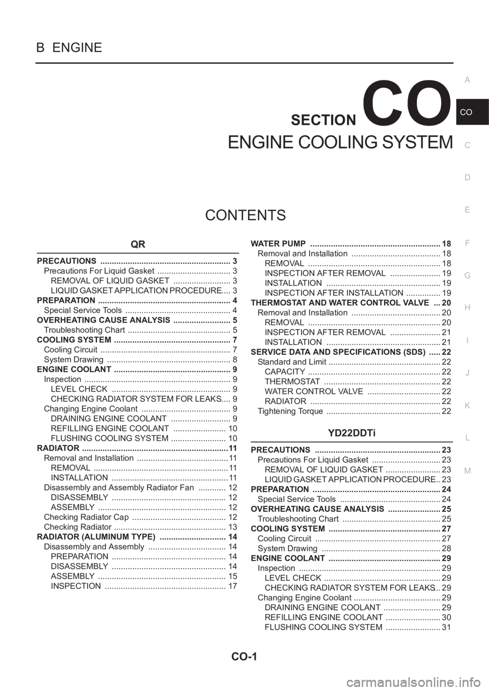
CO-1
ENGINE COOLING SYSTEM
B ENGINE
CONTENTS
C
D
E
F
G
H
I
J
K
L
M
SECTION
A
CO
ENGINE COOLING SYSTEM
QR
PRECAUTIONS .......................................................... 3
Precautions For Liquid Gasket ................................. 3
REMOVAL OF LIQUID GASKET .......................... 3
LIQUID GASKET APPLICATION PROCEDURE ..... 3
PREPARATION ........................................................... 4
Special Service Tools ............................................... 4
OVERHEATING CAUSE ANALYSIS .......................... 5
Troubleshooting Chart .............................................. 5
COOLING SYSTEM .................................................... 7
Cooling Circuit .......................................................... 7
System Drawing ....................................................... 8
ENGINE COOLANT .................................................... 9
Inspection ................................................................. 9
LEVEL CHECK ..................................................... 9
CHECKING RADIATOR SYSTEM FOR LEAKS ..... 9
Changing Engine Coolant ........................................ 9
DRAINING ENGINE COOLANT ........................... 9
REFILLING ENGINE COOLANT ........................ 10
FLUSHING COOLING SYSTEM ......................... 10
RADIATOR .................................................................11
Removal and Installation ......................................... 11
REMOVAL ............................................................ 11
INSTALLATION .................................................... 11
Disassembly and Assembly Radiator Fan ............. 12
DISASSEMBLY ................................................... 12
ASSEMBLY ......................................................... 12
Checking Radiator Cap .......................................... 12
Checking Radiator .................................................. 13
RADIATOR (ALUMINUM TYPE) .............................. 14
Disassembly and Assembly ................................... 14
PREPARATION ................................................... 14
DISASSEMBLY ................................................... 14
ASSEMBLY ......................................................... 15
INSPECTION ...................................................... 17WATER PUMP .......................................................... 18
Removal and Installation ........................................ 18
REMOVAL ........................................................... 18
INSPECTION AFTER REMOVAL ....................... 19
INSTALLATION ................................................... 19
INSPECTION AFTER INSTALLATION ................ 19
THERMOSTAT AND WATER CONTROL VALVE .... 20
Removal and Installation ........................................ 20
REMOVAL ........................................................... 20
INSPECTION AFTER REMOVAL ....................... 21
INSTALLATION ................................................
... 21
SERVICE DATA AND SPECIFICATIONS (SDS) ...... 22
Standard and Limit .................................................. 22
CAPACITY ........................................................... 22
THERMOSTAT .................................................... 22
WATER CONTROL VALVE ................................. 22
RADIATOR ....................................................... ... 22
Tightening Torque ................................................... 22
YD22DDTi
PRECAUTIONS ........................................................ 23
Precautions For Liquid Gasket ............................... 23
REMOVAL OF LIQUID GASKET ......................... 23
LIQUID GASKET APPLICATION PROCEDURE ... 23
PREPARATION ......................................................... 24
Special Service Tools ............................................. 24
OVERHEATING CAUSE ANALYSIS ........................ 25
Troubleshooting Chart ............................................ 25
COOLING SYSTEM .................................................. 27
Cooling Circuit ........................................................ 27
System Drawing ..................................................... 28
ENGINE COOLANT .................................................. 29
Inspection ............................................................... 29
LEVEL CHECK .................................................... 29
CHECKING RADIATOR SYSTEM FOR LEAKS ... 29
Changing Engine Coolant ....................................... 29
DRAINING ENGINE COOLANT .......................... 29
REFILLING ENGINE COOLANT ......................... 30
FLUSHING COOLING SYSTEM ......................... 31
Page 339 of 3833

RADIATOR
CO-33
[YD22DDTi]
C
D
E
F
G
H
I
J
K
L
MA
CO
Disassembly and Assembly Radiator FanEBS00BB1
DISASSEMBLY
1. Remove radiator fan.
2. Remove fan motor from fan shroud.
ASSEMBLY
Install in the reverse order of removal.
Checking Radiator CapEBS00BB2
●Check that there is no dirt or damage on the valve seat of the radiator cap negative-pressure valve.
●Check that there are no unusualness in the opening and closing
conditions of the negative-pressure valve.
●Pull the negative pressure valve to open it.
●Check that it close completely when released.
PBIC0238E
1. Radiator fan motors 2. Radiator fan shroud 3. Radiator fan
SMA967B
Page 340 of 3833

CO-34
[YD22DDTi]
RADIATOR
●Check radiator cap relief pressure.
●When connecting the radiator cap to the tester, apply engine
coolant to the cap seal part.
●Replace the radiator cap if there is an unusualness in the nega-
tive-pressure valve, or if the open-valve pressure is outside of
the standard values.
Checking RadiatorEBS00BRH
Check radiator for mud or clogging. If necessary, clean radiator as follows.
●Be careful not to bend or damage the radiator fins.
●When radiator is cleaned without removal, remove all surrounding parts such as cooling fan, radiator
shroud and horns. Then tape the harness and connectors to prevent water from entering.
1. Apply water by hose to the back side of the radiator core vertically downwards.
2. Apply water again to all radiator core surface once per minute.
3. Stop washing if any stains no longer flow out from the radiator.
4. Blow air into the back side of radiator core vertically downwards.
●Use compressed air lower than 490 kPa (4.9 bar 5 kg/cm2 , 71psi) and keep distance more than 30
cm(11.8 in).
5. Blow air again into all the radiator core surface once per minute until no water sprays out. Standard : 78 - 98 kPa (0.78 - 0.98 bar, 0.8 - 1.0 kg/
cm
2 , 11 - 14 psi)
Limit : 59 kPa (0.59 bar, 0.6 kg/cm
2 , 9 psi)
SLC135B
Page 348 of 3833

CO-42
[YD22DDTi]
THERMOSTAT AND WATER PIPING
INSPECTION AFTER REMOVAL
Thermostat
●Place a string so that it is caught in the valves of the thermostat.
Immerse fully in a container filled with water. Heat while stirring.
●The valve opening temperature is the temperature at which the
valve opens and falls from the thread.
●Continue heating. Check the full-open lift amount.
● After checking the full-open lift amount, lower the water temper-
ature and check the valve closing temperature.
Standard values
INSTALLATION
Install in the reverse order of removal paying attention to the following.
Thermostat
●Install the thermostat with the whole circumference of each
flange part fit securely inside the rubber ring.
●Install the thermostat with the jiggle valve facing upwards.
Heater Pipe
First apply a neutral detergent to the O-ring, then quickly insert the insertion parts oft he heater pipe into the
installation holes.
SLC252B
Item Thermostat
Valve opening temperature 80 - 84°C (176 - 183° F)
Full-open lift amount More than 10 mm/ 95°C (0.39 in/ 203 °F)
Valve closing temperature Approximately 77°C (171°F)
JLC300B
Page 349 of 3833

SERVICE DATA AND SPECIFICATIONS (SDS)
CO-43
[YD22DDTi]
C
D
E
F
G
H
I
J
K
L
MA
CO
SERVICE DATA AND SPECIFICATIONS (SDS)PFP:00030
Standard and LimitEBS00CU0
CAPACITY
Unit: (lmp qt)
THERMOSTAT
RADIATOR
Unit: kPa (bar, kg/cm2 , psi)
Tightening TorqueEBS00BKE
Unit: N·m (kg-m, ft-lb)
Unit: N·m (kg-m, in-lb)*
Engine coolant capacity [With reservoir tank (MAX level)] 9.5 (8-3/8)
Reservoir tank0.6 (1/2)
Valve opening temperature 80 - 84°C (176 - 183°F)
Va l v e l i f tMore than 10 mm/ 95°C (0.39 in/203°F)
Valve closing temperature Approximately 77°C (171°F)
Cap relief pressureStandard 78 - 98 (0.78 - 0.98, 0.8 - 1.0, 11 - 14)
Limit 59 (0.59, 0.6, 9)
Leakage test pressure 157 (1.57, 1.6, 23)
Cylinder block drain plug 7.8 - 11.8 (0.8 - 1.2, 69 - 104)*
Air relief plug6.7 - 7.9 (0.68 - 0.81, 59 - 70)*
Radiator mounting bracket
Radiator fan assembly
Radiator fan
Radiator fan motor3.8 - 4.5 (0.39 - 0.45, 34 - 39)*
3.8 - 4.5 (0.39 - 0.45, 34 - 39)*
2.9 - 3.9 (0.30 - 0.40, 26 - 34)*
3.9 - 4.9 (0.40 - 0.50, 35 - 43)*
Water pump
Water pump pulley
Water inlet
Thermostat housing
Water inlet pipe
Hater return pipe23.0 - 30.0 (2.3 - 3.1, 17 - 22)
7.3 - 9.6 (0.74 - 0.98, 65 - 85)*
21.0 - 28.0 (2.1 - 2.9, 16 - 20)
21.0 - 28.0 (2.1 - 2.9, 16 - 20)
21.0 - 28.0 (2.1 - 2.9, 16 - 20)
21.0 - 28.0 (2.1 - 2.9, 16 - 20)
Page 1924 of 3833

EC-1574
[YD]
SERVICE DATA AND SPECIFICATIONS (SDS)
SERVICE DATA AND SPECIFICATIONS (SDS)
PFP:00100
General SpecificationsEBS00361
Mass Air Flow SensorEBS00CU1
Engine Coolant Temperature SensorEBS00363
Common Rail Fuel Pressure SensorEBS00BLQ
Crankshaft Position Sensor (TDC)EBS00BLS
Camshaft Position SensorEBS00364
Glow PlugEBS00365
EGR Volume Control ValveEBS00367
EngineYD22DDTi
Idle speed725± 25 rpm
Maximum engine speed 4,800 rpm
Supply voltageBattery voltage (11 - 14V)
Ignition switch "ON" (Engine stopped.) Approx. 1.0V
Idle (Engine is warmed up to normal operating temperature.) 1.0 - 2.5V
2,000 rpm (Engine is warmed up to normal operating tempera-
ture.)2.1 - 2.7V
Temperature °C (°F) Resistance kΩ
20 (68) 2.1 - 2.9
50 (122) 0.68 - 1.00
90 (194) 0.236 - 0.260
Supply voltageApproximately 5V
Idle (Engine is warmed up to normal operating temperature.) 1.6 - 1.8V
2,000 rpm (Engine is warmed up to normal operating tempera-
ture.)1.8 - 2.0V
Resistance [at 20°C (68°F)] Ω1,850 - 2,450
Resistance [at 20°C (68°F)] Ω1,850 - 2,450
Resistance [at 25°C (77°F)] Ω Approximately 0.8
Resistance [at 25°C (77°F)] Ω13 - 17
Page 2940 of 3833

PS-30
POWER STEERING OIL PUMP
Disassembly and Assembly (YD22DDTi engine model)
EGS000AJ
INSPECTION BEFORE DISASSEMBLY
Disassemble power steering oil pump only when any of following
cases meets.
●If oil leak is found on oil pump.
●Oil pump pulley is deformed or damaged.
●Performance of oil pump is low.
1. Rear bracket 2. Rear body 3. Dowel pin
4. Side plate seal 5. Cam ring 6. Vane
7. Rotor 8. Side plate 9. O-ring (Outer)
10. O-ring (Inner) 11. Front body 12. Drive shaft rear oil sear
13. Drive shaft front oil seal 14. Drive shaft 15. Snap ring
16. O-ring 17. Outlet connector 18. Connector seal
19. Flow control valve 20. Flow control valve spring 21. Inlet connector
22. O-ring 23. Copper washer
SST882CA
SST883C
Page 3788 of 3833

MA-8
PERIODIC MAINTENANCE
Abbreviations: I = Inspect and correct or replace as necessary,R = Replace, L = Lubricate.
NOTE:
●(1) Inspect once per year.
● Maintenance items with “ ” should be performed more frequently according to “Maintenance Under Severe Driving
Conditions”.
ENGINE AND EMISSION CONTROL MAINTENANCE (YD22DDTI DIESEL ENGINE)
(Annual Mileage <30,000 Km/year)
Abbreviations: I = Inspect and correct or replace as necessary,R = Replace, D = Check filter and drain water MAINTENANCE OPERATIONMAINTENANCE INTERVAL
Reference
page Perform either at number of kilometers
(miles) or months, whichever comes
first.km x 1,000
(Miles x 1,000)
Months15
(9)
1230
(18)
2445
(27)
3660
(36)
4875
(45)
6090
(54)
72105
(63)
84120
(72)
96
Underhood and under vehicle
Headlamp aiming I I I I I I I ILT- 6
Brake & clutch, systems and fluid (For
level & leaks)IIIIIIIIMA-35,MA-
39
Brake fluidRRRRMA-39
Brake booster vacuum hoses, connec-
tions & check valveIIIIBR-19
Power steering fluid & lines (For level
& leaks)IIIIIIIIMA-40
Manual transaxle gear oil (For level &
leaks)IIIIIIIIMA-35
Automatic transaxle fluid (For level &
leaks)IIIIIIIIMA-36
Transfer gear oil (For level & leaks) I I I I I I I IMA-37
Differential gear oil (For level & leaks
or replace)IIIRIIIRMA-38,MA-
38
Steering gear & linkage, axle & sus-
pension parts, propeller shaft, front
drive shafts & exhaust systemIIIIIIIIMA-40,MA-
41 ,MA-37
,MA-41,
"Drive
Shaft"
Wheel alignment (If necessary, rotate
& balance wheels)IIIIIIIIFSU-6,MA-
38
Brake pads, rotors & other brake com-
ponentsIIIIIIIIMA-40,MA-
40 ,MA-39
Foot brake, parking brake & clutch (For
free play, stroke & operation)IIIIIIIIBR-6PB-3,
CL-5
Ventilation air filterRRRRAT C - 1 2 1
Body corrosion See NOTE (1)MA-42
MAINTENANCE OPERATIONMAINTENANCE INTERVAL
Refer-
ence page Perform either at number of kilometers (miles) or
months, whichever comes first.km x 1,000
(Miles x
1,000)
Months20
(12)
1240
(24)
2460
(36)
3680
(48)
48100
(60)
60120
(72)
72
Engine compartment and under vehicle
Intake & exhaust valve clearanceSee NOTE
(1)EM-163
Drive belts I I I I I IMA-26
Engine oil (Use API CD, CE, CF, CF-4 oil.)See NOTE
(2)RRRRRRMA-32