gas type NISSAN X-TRAIL 2001 Service Repair Manual
[x] Cancel search | Manufacturer: NISSAN, Model Year: 2001, Model line: X-TRAIL, Model: NISSAN X-TRAIL 2001Pages: 3833, PDF Size: 39.49 MB
Page 7 of 3833
PRECAUTIONS
GI-5
C
D
E
F
G
H
I
J
K
L
MB
GI
●Use approved bonding agent, sealants or their equivalents when required.
●Use tools and recommended special tools where specified for safe and efficient service repairs.
●When repairing the fuel, oil, water, vacuum or exhaust systems, check all affected lines for leaks.
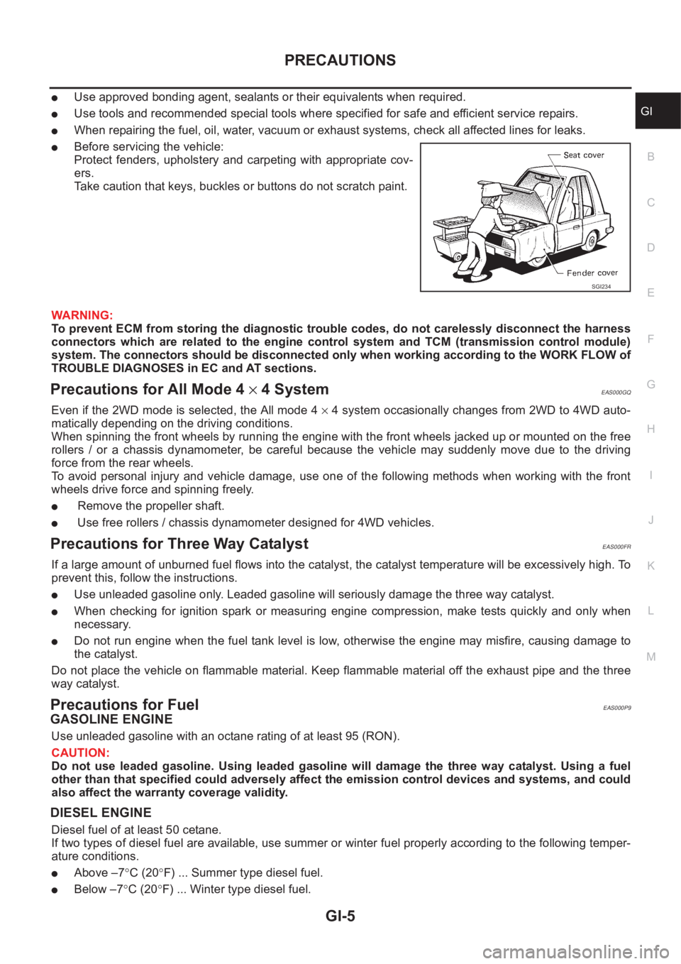
●Before servicing the vehicle:
Protect fenders, upholstery and carpeting with appropriate cov-
ers.
Take caution that keys, buckles or buttons do not scratch paint.
WARNING:
To prevent ECM from storing the diagnostic trouble codes, do not carelessly disconnect the harness
connectors which are related to the engine control system and TCM (transmission control module)
system. The connectors should be disconnected only when working according to the WORK FLOW of
TROUBLE DIAGNOSES in EC and AT sections.
Precautions for All Mode 4 × 4 SystemEAS000GQ
Even if the 2WD mode is selected, the All mode 4 × 4 system occasionally changes from 2WD to 4WD auto-
matically depending on the driving conditions.
When spinning the front wheels by running the engine with the front wheels jacked up or mounted on the free
rollers / or a chassis dynamometer, be careful because the vehicle may suddenly move due to the driving
force from the rear wheels.
To avoid personal injury and vehicle damage, use one of the following methods when working with the front
wheels drive force and spinning freely.
● Remove the propeller shaft.
● Use free rollers / chassis dynamometer designed for 4WD vehicles.
Precautions for Three Way CatalystEAS000FR
If a large amount of unburned fuel flows into the catalyst, the catalyst temperature will be excessively high. To
prevent this, follow the instructions.
●Use unleaded gasoline only. Leaded gasoline will seriously damage the three way catalyst.
●When checking for ignition spark or measuring engine compression, make tests quickly and only when
necessary.
●Do not run engine when the fuel tank level is low, otherwise the engine may misfire, causing damage to
the catalyst.
Do not place the vehicle on flammable material. Keep flammable material off the exhaust pipe and the three
way catalyst.
Precautions for FuelEAS000P9
GASOLINE ENGINE
Use unleaded gasoline with an octane rating of at least 95 (RON).
CAUTION:
Do not use leaded gasoline. Using leaded gasoline will damage the three way catalyst. Using a fuel
other than that specified could adversely affect the emission control devices and systems, and could
also affect the warranty coverage validity.
DIESEL ENGINE
Diesel fuel of at least 50 cetane.
If two types of diesel fuel are available, use summer or winter fuel properly according to the following temper-
ature conditions.
●Above –7°C (20°F) ... Summer type diesel fuel.
●Below –7°C (20°F) ... Winter type diesel fuel.
SGI234
Page 307 of 3833
CO-1
ENGINE COOLING SYSTEM
B ENGINE
CONTENTS
C
D
E
F
G
H
I
J
K
L
M
SECTION
A
CO
ENGINE COOLING SYSTEM
QR
PRECAUTIONS .......................................................... 3
Precautions For Liquid Gasket ................................. 3
REMOVAL OF LIQUID GASKET .......................... 3
LIQUID GASKET APPLICATION PROCEDURE ..... 3
PREPARATION ........................................................... 4
Special Service Tools ............................................... 4
OVERHEATING CAUSE ANALYSIS .......................... 5
Troubleshooting Chart .............................................. 5
COOLING SYSTEM .................................................... 7
Cooling Circuit .......................................................... 7
System Drawing ....................................................... 8
ENGINE COOLANT .................................................... 9
Inspection ................................................................. 9
LEVEL CHECK ..................................................... 9
CHECKING RADIATOR SYSTEM FOR LEAKS ..... 9
Changing Engine Coolant ........................................ 9
DRAINING ENGINE COOLANT ........................... 9
REFILLING ENGINE COOLANT ........................ 10
FLUSHING COOLING SYSTEM ......................... 10
RADIATOR .................................................................11
Removal and Installation ......................................... 11
REMOVAL ............................................................ 11
INSTALLATION .................................................... 11
Disassembly and Assembly Radiator Fan ............. 12
DISASSEMBLY ................................................... 12
ASSEMBLY ......................................................... 12
Checking Radiator Cap .......................................... 12
Checking Radiator .................................................. 13
RADIATOR (ALUMINUM TYPE) .............................. 14
Disassembly and Assembly ................................... 14
PREPARATION ................................................... 14
DISASSEMBLY ................................................... 14
ASSEMBLY ......................................................... 15
INSPECTION ...................................................... 17WATER PUMP .......................................................... 18
Removal and Installation ........................................ 18
REMOVAL ........................................................... 18
INSPECTION AFTER REMOVAL ....................... 19
INSTALLATION ................................................... 19
INSPECTION AFTER INSTALLATION ................ 19
THERMOSTAT AND WATER CONTROL VALVE .... 20
Removal and Installation ........................................ 20
REMOVAL ........................................................... 20
INSPECTION AFTER REMOVAL ....................... 21
INSTALLATION ................................................
... 21
SERVICE DATA AND SPECIFICATIONS (SDS) ...... 22
Standard and Limit .................................................. 22
CAPACITY ........................................................... 22
THERMOSTAT .................................................... 22
WATER CONTROL VALVE ................................. 22
RADIATOR ....................................................... ... 22
Tightening Torque ................................................... 22
YD22DDTi
PRECAUTIONS ........................................................ 23
Precautions For Liquid Gasket ............................... 23
REMOVAL OF LIQUID GASKET ......................... 23
LIQUID GASKET APPLICATION PROCEDURE ... 23
PREPARATION ......................................................... 24
Special Service Tools ............................................. 24
OVERHEATING CAUSE ANALYSIS ........................ 25
Troubleshooting Chart ............................................ 25
COOLING SYSTEM .................................................. 27
Cooling Circuit ........................................................ 27
System Drawing ..................................................... 28
ENGINE COOLANT .................................................. 29
Inspection ............................................................... 29
LEVEL CHECK .................................................... 29
CHECKING RADIATOR SYSTEM FOR LEAKS ... 29
Changing Engine Coolant ....................................... 29
DRAINING ENGINE COOLANT .......................... 29
REFILLING ENGINE COOLANT ......................... 30
FLUSHING COOLING SYSTEM ......................... 31
Page 570 of 3833
![NISSAN X-TRAIL 2001 Service Repair Manual EC-220
[QR25(WITH EURO-OBD)]
DTC P0300 - P0304 MULTIPLE CYLINDER MISFIRE, NO. 1 - 4 CYLINDER MIS-
FIRE
5. CHECK IGNITION SPARK
1. Disconnect ignition coil assembly from rocker cover.
2. Connect a know](/img/5/57405/w960_57405-569.png "NISSAN X-TRAIL 2001 Service Repair Manual EC-220
[QR25(WITH EURO-OBD)]
DTC P0300 - P0304 MULTIPLE CYLINDER MISFIRE, NO. 1 - 4 CYLINDER MIS-
FIRE
5. CHECK IGNITION SPARK
1. Disconnect ignition coil assembly from rocker cover.
2. Connect a know")
EC-220
[QR25(WITH EURO-OBD)]
DTC P0300 - P0304 MULTIPLE CYLINDER MISFIRE, NO. 1 - 4 CYLINDER MIS-
FIRE
5. CHECK IGNITION SPARK
1. Disconnect ignition coil assembly from rocker cover.
2. Connect a known-good spark plug to the ignition coil assembly.
3. Place end of spark plug against a suitable ground and crank engine.
4. Check for spark.
OK or NG
OK >> GO TO 6.
NG >> Check ignition coil, power transistor and their circuits.
Refer to EC-379, "
IGNITION SIGNAL" .
6. CHECK SPARK PLUGS
Remove the spark plugs and check for fouling, etc.
OK or NG
OK >> GO TO 7.
NG >> Repair or replace spark plug(s) with standard type
one(s). For spark plug type, refer to MA-24, "
Checking
and Changing Spark Plugs" .
7. CHECK COMPRESSION PRESSURE
Check compression pressure. Refer to EM-59, "
CHECKING COMPRESSION PRESSURE" .
OK or NG
OK >> GO TO 8.
NG >> Check pistons, piston rings, valves, valve seats and cylinder head gaskets.
8. CHECK FUEL PRESSURE
1. Install all removed parts.
2. Release fuel pressure to zero. Refer to EC-42, "
FUEL PRESSURE RELEASE" .
3. Install fuel pressure gauge and check fuel pressure. Refer to EC-42, "
FUEL PRESSURE CHECK" .
OK or NG
OK >> GO TO 9.
NG >> Follow the Instruction of “FUEL PRESSURE CHECK”.
SEF575Q
SEF156I
Standard:
1,190 kPa (11.9 bar, 12.1 kg/cm2 , 172 psi)/250
rpm
Minimum:
990 kPa (9.9 bar, 10.1 kg/cm
2 , 144 psi)/250 rpm
Difference between each
cylinder:98 kPa (0.98 bar, 1.0 kg/cm
2 , 14 psi)/250 rpm
At idle: Approx. 350 kPa (3.5 bar, 3.57 kg/cm
2 , 51 psi)
Page 1299 of 3833
![NISSAN X-TRAIL 2001 Service Repair Manual DTC P0300 - P0304 MULTIPLE CYLINDER MISFIRE, NO. 1 - 4 CYLINDER MIS-
FIRE
EC-949
[QR20(WITH EURO-OBD)]
C
D
E
F
G
H
I
J
K
L
MA
EC
5.CHECK IGNITION SPARK
1. Disconnect ignition coil assembly from rocker](/img/5/57405/w960_57405-1298.png "NISSAN X-TRAIL 2001 Service Repair Manual DTC P0300 - P0304 MULTIPLE CYLINDER MISFIRE, NO. 1 - 4 CYLINDER MIS-
FIRE
EC-949
[QR20(WITH EURO-OBD)]
C
D
E
F
G
H
I
J
K
L
MA
EC
5.CHECK IGNITION SPARK
1. Disconnect ignition coil assembly from rocker")
DTC P0300 - P0304 MULTIPLE CYLINDER MISFIRE, NO. 1 - 4 CYLINDER MIS-
FIRE
EC-949
[QR20(WITH EURO-OBD)]
C
D
E
F
G
H
I
J
K
L
MA
EC
5.CHECK IGNITION SPARK
1. Disconnect ignition coil assembly from rocker cover.
2. Connect a known-good spark plug to the ignition coil assembly.
3. Place end of spark plug against a suitable ground and crank engine.
4. Check for spark.
OK or NG
OK >> GO TO 6.
NG >> Check ignition coil, power transistor and their circuits.
Refer to EC-1074, "
IGNITION SIGNAL" .
6.CHECK SPARK PLUGS
Remove the spark plugs and check for fouling, etc.
OK or NG
OK >> GO TO 7.
NG >> Repair or replace spark plug(s) with standard type
one(s). For spark plug type, refer to MA-24, "
Checking
and Changing Spark Plugs" .
7.CHECK COMPRESSION PRESSURE
Check compression pressure. Refer to EM-59, "
CHECKING COMPRESSION PRESSURE" .
OK or NG
OK >> GO TO 8.
NG >> Check pistons, piston rings, valves, valve seats and cylinder head gaskets.
8.CHECK FUEL PRESSURE
1. Install all removed parts.
2. Release fuel pressure to zero. Refer to EC-775, "
FUEL PRESSURE RELEASE" .
3. Install fuel pressure gauge and check fuel pressure. Refer to EC-775, "
FUEL PRESSURE CHECK" .
OK or NG
OK >> GO TO 9.
NG >> Follow the Instruction of “FUEL PRESSURE CHECK”.
SEF575Q
SEF156I
Standard:
1,190 kPa (11.9 bar, 12.1 kg/cm2 , 172 psi)/250
rpm
Minimum:
990 kPa (9.9 bar, 10.1 kg/cm
2 , 144 psi)/250 rpm
Difference between each
cylinder:98 kPa (0.98 bar, 1.0 kg/cm
2 , 14 psi)/250 rpm
At idle: Approx. 350 kPa (3.5 bar, 3.57 kg/cm
2 , 51 psi)
Page 2743 of 3833
PRECAUTIONS
BR-3
C
D
E
G
H
I
J
K
L
MA
B
BR
PRECAUTIONSPFP:00001
Precautions for Supplemental Restraint System (SRS) “AIR BAG” and “SEAT
BELT PRE-TENSIONER”
EFS002F9
The Supplemental Restraint System such as “AIR BAG” and “SEAT BELT PRE-TENSIONER”, used along
with a front seat belt, helps to reduce the risk or severity of injury to the driver and front passenger for certain
types of collision. Information necessary to service the system safely is included in the SRS and SB section of
this Service Manual.
WARNING:
●To avoid rendering the SRS inoperative, which could increase the risk of personal injury or death
in the event of a collision which would result in air bag inflation, all maintenance must be per-
formed by an authorized NISSAN/INFINITI dealer.
●Improper maintenance, including incorrect removal and installation of the SRS, can lead to per-
sonal injury caused by unintentional activation of the system. For removal of Spiral Cable and Air
Bag Module, see the SRS section.
●Do not use electrical test equipment on any circuit related to the SRS unless instructed to in this
Service Manual. SRS wiring harnesses can be identified by yellow and/or orange harness connec-
tors.
Precautions for Brake SystemEFS000BZ
●Clean dust on brake pads, shoes, drums, and back plates with a vacuum dust collector. Do not blow with
compressed air.
●Recommended fluid is brake fluid “DOT 3” or “DOT 4”.
●Never reuse drained brake fluid.
●Be careful not to splash brake fluid on painted areas such as the body. If brake fluid is splashed or spilled
on paint, wipe it off and flush the area with water immediately.
●Use only clean brake fluid when cleaning master cylinder and disc brake components.
●Never use mineral oils such as gasoline or kerosene to clean. They will ruin the rubber parts and cause
improper operation.
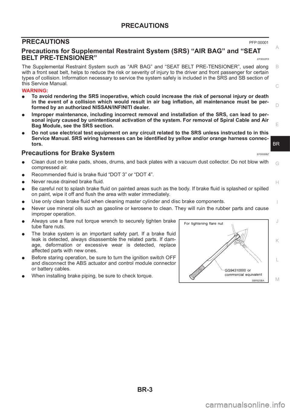
●Always use a flare nut torque wrench to securely tighten brake
tube flare nuts.
●The brake system is an important safety part. If a brake fluid
leak is detected, always disassemble the related parts. If dam-
age, deformation or excessive wear is detected, replace
affected parts with new ones.
●Before staring operation, be sure to turn the ignition switch OFF
and disconnect the ABS actuator and control module connector
or battery cables.
●When installing brake piping, be sure to check torque.SBR820BA
Page 2788 of 3833
![NISSAN X-TRAIL 2001 Service Repair Manual BRC-4
[4WD/ABS]
PRECAUTIONS
[4WD/ABS]PRECAUTIONSPFP:00001
Precautions for brake systemEFS001B6
●Recommended fluid is brake fluid “DOT 3 ”or “DOT 4”.
●Never reuse drained brake fluid.
●Be](/img/5/57405/w960_57405-2787.png "NISSAN X-TRAIL 2001 Service Repair Manual BRC-4
[4WD/ABS]
PRECAUTIONS
[4WD/ABS]PRECAUTIONSPFP:00001
Precautions for brake systemEFS001B6
●Recommended fluid is brake fluid “DOT 3 ”or “DOT 4”.
●Never reuse drained brake fluid.
●Be")
BRC-4
[4WD/ABS]
PRECAUTIONS
[4WD/ABS]PRECAUTIONSPFP:00001
Precautions for brake systemEFS001B6
●Recommended fluid is brake fluid “DOT 3 ”or “DOT 4”.
●Never reuse drained brake fluid.
●Be careful not to splash brake fluid on painted areas.
●To clean or wash all parts of master cylinder, disc brake caliper and wheel cylinder, use clean brake fluid.
●Never use mineral oils such as gasoline or kerosene. They will ruin rubber parts of the hydraulic system.
●Use flare nut wrench when removing and installing brake tube.
●Always torque brake lines when installing.
●Burnish the brake contact surfaces after refinishing or replacing
drums or rotors, after replacing pads or linings, or if a soft pedal
occurs at very low mileage. Refer to BR-10, "
Brake Burnishing
Procedure" .
●Before working, turn OFF ignition switch. Disconnect connectors
for ABS actuator and control module or battery terminals.
WARNING:
●Clean brake pads and shoes with a waste cloth, then wipe
with a dust collector.
Precautions for brake controlEFS001B7
●If malfunction is indicated by 4WD warning lamp and/or ABS warning lamp, collect necessary information
from customer (what symptoms are present under what conditions). Find out possible causes before start-
ing service. Besides electrical system inspection, check operation of ABS actuator.
●If malfunction is detected, proceed to trouble diagnosis after checking tire pressure and tire wear.
●Stopping distance or steering stability may be deteriorated by the following conditions. Tire size and type
are in improper combination. Brake pads are not Nissan genuine parts.
●Fitting tires of different size on vehicle can be cause of longitudinal vibration. Always use tires of the same
size and brand. Exchange front and rear tires on the following conditions: Longitudinal vibration occurs in
vehicle with tires of the same size and brand. After replacement, perform trouble diagnosis. 1580|None
●4WD/ABS function may have a failure or error under following condition: There is radio, antenna, or
antenna lead-in wire (including wiring) near control module.
●If aftermarket parts (e.g. Car stereo equipment, CD player) have been installed, check electrical har-
nesses for pinches, open, and improper wiring.
SBR820BA
Page 2838 of 3833
![NISSAN X-TRAIL 2001 Service Repair Manual BRC-54
[ESP/TCS/ABS]
PRECAUTIONS
[ESP/TCS/ABS]PRECAUTIONSPFP:00001
Precautions for Brake SystemEFS0019O
●Recommended fluid is brake fluid “DOT 3” or “DOT 4”.
●Never reuse drained brake flu](/img/5/57405/w960_57405-2837.png "NISSAN X-TRAIL 2001 Service Repair Manual BRC-54
[ESP/TCS/ABS]
PRECAUTIONS
[ESP/TCS/ABS]PRECAUTIONSPFP:00001
Precautions for Brake SystemEFS0019O
●Recommended fluid is brake fluid “DOT 3” or “DOT 4”.
●Never reuse drained brake flu")
BRC-54
[ESP/TCS/ABS]
PRECAUTIONS
[ESP/TCS/ABS]PRECAUTIONSPFP:00001
Precautions for Brake SystemEFS0019O
●Recommended fluid is brake fluid “DOT 3” or “DOT 4”.
●Never reuse drained brake fluid.
●Be careful not to splash brake fluid on painted areas; it may cause paint damage. If brake fluid is splashed
on painted areas, wash it away with water immediately.
●Never use mineral oils such as gasoline or kerosene. They will ruin rubber parts of hydraulic system.
●Use flare nut wrench when removing and installing brake tubes.
●Always torque brake lines when installing.
●Before working, turn the ignition switch OFF and disconnect the
connectors for the ESP/TCS/ABS actuator and control unit or
the battery terminals.
●Burnish the brake contact surfaces after refinishing or replacing
drums or rotors, after replacing pads or linings, or if a soft pedal
occurs at very low mileage. Refer to BR-10, "
Brake Burnishing
Procedure" .
WARNING:
Clean brakes with a vacuum dust collector to minimize risk
of health hazard from powder caused by friction.
Precautions for Brake ControlEFS0019P
●During the ESP/TCS/ABS operation, the brake pedal vibrates lightly and its mechanical noise may be
heard. This is a normal condition.
●Just after starting the vehicle after ignition switch ON, the brake pedal may vibrate or the motor operating
noise may be heard from the engine compartment. This is a normal status of the operation check.
●The stopping distance may be longer than that of vehicles without ABS when the vehicle drives on rough,
gravel, or snowy (fresh deep snow) road.
●If a malfunction is indicated by the ABS warning lamp, or other warning lamps, collect the necessary infor-
mation from the customer (what symptoms are present under what conditions) and find out the possible
causes before starting the service. Besides the electrical system inspection, check the booster operation,
brake fluid level, and oil leaks.
●If the tire size and type are used in a improper combination, or the brake pads are not NISSAN genuine
parts, the stopping distance or steering stability may deteriorate.
●If there is a radio, antenna, or antenna lead-in wire (including wiring) near the control unit, the ESP/TCS/
ABS function may have a malfunction or error.
●If aftermarket parts (e.g. Car stereo equipment, CD player) have been installed, check the electrical har-
nesses for pinches, open, and improper wiring.
Precautions for CAN SystemEFS001CP
FOR INSPECTION
●Do not apply voltage of 7.0V or higher to the measurement terminals.
●Use the tester with its open terminal voltage being 7.0V or less.
●Before harness inspection, turn the ignition switch off, disconnect the negative battery terminal.
SBR820BA
Page 2912 of 3833
PS-2
PRECAUTIONS
PRECAUTIONS
PFP:00001
Precautions for Supplemental Restraint System (SRS) “AIR BAG” and “SEAT
BELT PRE-TENSIONER”
EGS000IZ
The Supplemental Restraint System such as “AIR BAG” and “SEAT BELT PRE-TENSIONER”, used along
with a front seat belt, helps to reduce the risk or severity of injury to the driver and front passenger for certain
types of collision. Information necessary to service the system safely is included in the SRS and SB section of
this Service Manual.
WARNING:
●To avoid rendering the SRS inoperative, which could increase the risk of personal injury or death
in the event of a collision which would result in air bag inflation, all maintenance must be per-
formed by an authorized NISSAN/INFINITI dealer.
●Improper maintenance, including incorrect removal and installation of the SRS, can lead to per-
sonal injury caused by unintentional activation of the system. For removal of Spiral Cable and Air
Bag Module, see the SRS section.
●Do not use electrical test equipment on any circuit related to the SRS unless instructed to in this
Service Manual. SRS wiring harnesses can be identified by yellow and/or orange harness connec-
tors.
CautionEGS00049
●Always follow the warnings and the cautions below in disassembly procedures:
–Work in a clean, dust-free place. No dust proof device is necessary.
–Clean outside of unit before disassembly.
–Clean parts to be disassembled. Be careful not to allow any dirt or other foreign materials to enter or con-
tact with parts.
–Assemble disassembled parts properly, following order shown in manual. If work has been suspended in
the middle of assembly, place a clean cover over parts. This will prevent them from being contaminated.
–Use paper towels when removing dirt and other foreign materials. Cloth shop towels can leave lint on
cleaned parts that might affect operation of parts.
–Clean disassembled parts (except rubber parts) with kerosene. Drain oil by blowing with air or absorbing
with shop papers.
–Before assembling, apply Nissan power steering fluid to O-rings and seals.
–Replace gaskets and O-rings with new ones. Be careful not to damage any O-rings, oil seals, and gaskets
during assembly.
●If following part is scratched after disassembly of steering pump, replace applicable part: case, rear body,
side plate, pulley, rotor, vane, or flow control valve
●Mark source of fluid leak with a white marker for identification.
● Seals and copper washers must not be reused.
Page 3277 of 3833
ATC-1
AUTOMATIC AIR CONDITIONER
J AIR CONDITIONER
CONTENTS
C
D
E
F
G
H
I
K
L
M
SECTION
A
B
AT C
AUTOMATIC AIR CONDITIONER
PRECAUTIONS .......................................................... 4
Precautions for Supplemental Restraint System
(SRS) “AIR BAG” and “SEAT BELT PRE-TEN-
SIONER” .................................................................. 4
Precautions for Working with HFC-134a (R-134a) ..... 4
General Refrigerant Precautions .............................. 5
Lubricant Precautions .............................................. 5
Precautions for Refrigerant Connection ................... 5
FEATURES OF NEW TYPE REFRIGERANT
CONNECTION ...................................................... 6
O-RING AND REFRIGERANT CONNECTION ..... 7
Precautions for Servicing Compressor ..................... 9
Precautions for Service Equipment ........................ 10
RECOVERY/RECYCLING EQUIPMENT ............ 10
ELECTRONIC LEAK DETECTOR ...................... 10
VACUUM PUMP ................................................. 10
MANIFOLD GAUGE SET .................................... 10
SERVICE HOSES ................................................ 11
SERVICE COUPLERS ......................................... 11
REFRIGERANT WEIGHT SCALE ....................... 11
CALIBRATING ACR4 WEIGHT SCALE ............... 11
CHARGING CYLINDER ...................................... 12
Precautions for Leak Detection Dye ....................... 12
IDENTIFICATION ................................................ 12
IDENTIFICATION LABEL FOR VEHICLE ........... 13
Wiring Diagrams and Trouble Diagnosis ................ 13
PREPARATION ......................................................... 14
Special Service Tools ............................................. 14
WITH GASOLINE ENGINE (CWV-615M COM-
PRESSOR) ......................................................... 14
WITH DIESEL ENGINE (DKV-11G COMPRES-
SOR) ................................................................... 14
HFC-134a (R-134a) Service Tools and Equipment ... 15
REFRIGERATION SYSTEM ..................................... 18
Refrigerant Cycle ................................................... 18
REFRIGERANT FLOW ....................................... 18
FREEZE PROTECTION (WITH GASOLINE
ENGINE: CWV-615M COMPRESSOR) .............. 18
Refrigerant System Protection ............................... 18
REFRIGERANT PRESSURE SENSOR (WITH GASOLINE ENGINE: CWV-615M COMPRES-
SOR) ................................................................... 18
DUAL-PRESSURE SWITCH (WITH DIESEL
ENGINE: DKV-11G COMPRESSOR) .................. 18
PRESSURE RELIEF VALVE (WITH GASOLINE
ENGINE: CWV-615M COMPRESSOR) .............. 18
V-6 Variable Displacement Compressor (With Gas-
oline Engine: CWV-615M Compressor) .................. 19
GENERAL INFORMATION ................................. 19
DESCRIPTION .................................................... 20
Component Layout ................................................. 23
LUBRICANT .............................................................. 24
Maintenance of Lubricant Quantity in Compressor ... 24
LUBRICANT ........................................................ 24
LUBRICANT RETURN OPERATION .................. 24
LUBRICANT ADJUSTING PROCEDURE FOR
COMPONENTS REPLACEMENT EXCEPT
COMPRESSOR .................................................. 25
LUBRICANT ADJUSTING PROCEDURE FOR
COMPRESSOR REPLACEMENT ....................... 25
AIR CONDITIONER CONTROL ............................... 27
Overview Air Conditioner LAN Control System ...... 27
System Construction .............................................. 27
OPERATION ........................................................ 27
TRANSMISSION DATA AND TRANSMISSION
ORDER ............................................................... 28
AIR MIX DOOR CONTROL (AUTOMATIC TEM-
PERATURE CONTROL) ..................................... 28
FAN SPEED CONTROL ...................................... 29
INTAKE DOOR CONTROL ................................. 29
OUTLET DOOR CONTROL ................................ 29
MAGNET CLUTCH CONTROL ........................... 29
SELF-DIAGNOSTIC SYSTEM ............................ 29
Overview of Control system .................................... 29
Control Operation ................................................... 30
DISPLAY SCREEN .............................................. 30
AUTO SWITCH ................................................... 30
TEMPERATURE DIAL (POTENTIO TEMPERA-
TURE CONTROL) ............................................... 30
A/C SWITCH ....................................................... 30
Page 3281 of 3833
PRECAUTIONS
ATC-5
C
D
E
F
G
H
I
K
L
MA
B
AT C
General Refrigerant PrecautionsEJS000T2
WARNING:
●Do not release refrigerant into the air. Use approved recovery/recycling equipment to capture the
refrigerant every time an air conditioning system is discharged.
●Always wear eye and hand protection (goggles and gloves) when working with any refrigerant or
air conditioning system.
●Do not store or heat refrigerant containers above 52°C (125°F).
●Do not heat a refrigerant container with an open flame; if container warming is required, place the
bottom of the container in a warm pail of water.
●Do not intentionally drop, puncture, or incinerate refrigerant containers.
●Keep refrigerant away from open flames: poisonous gas will be produced if refrigerant burns.
●Refrigerant will displace oxygen, therefore be certain to work in well ventilated areas to prevent
suffocation.
●Do not pressure test or leak test HFC-134a (R-134a) service equipment and/or vehicle air condi-
tioning systems with compressed air during repair. Some mixtures of air and HFC-134a (R-134a)
have been shown to be combustible at elevated pressures. These mixtures, if ignited, may cause
injury or property damage. Additional health and safety information may be obtained from refriger-
ant manufacturers.
Lubricant PrecautionsEJS0027Y
●Use only specified lubricant for the HFC-134a (R-134a) A/C system and HFC-134a (R-134a) components.
If lubricant other than that specified is used, compressor malfunction is likely to occur.
●The specified HFC-134a (R-134a) lubricant rapidly absorbs moisture from the atmosphere. The following
handling precautions must be observed:
●When removing refrigerant components from a vehicle, immediately cap (seal) the component to minimize
the entry of moisture from the atmosphere.
●When installing refrigerant components to a vehicle, do not remove the caps (unseal) until just before con-
necting the components. Connect all refrigerant loop components as quickly as possible to minimize the
entry of moisture into system.
●Only use the specified lubricant from a sealed container. Immediately reseal containers of lubricant. With-
out proper sealing, lubricant will become moisture saturated and should not be used.
●Avoid breathing A/C refrigerant and lubricant vapor or mist. Exposure may irritate eyes, nose and throat.
Remove HFC-134a (R-134a) from the A/C system, using certified service equipment meeting require-
ments of SAE J2210 HFC-134a (R-134a) recycling equipment, or J2209 HFC-134a (R-134a) recovery
equipment. If accidental system discharge occurs, ventilate work area before resuming service. Additional
health and safety information may be obtained from refrigerant and lubricant manufacturers.
●Do not allow lubricant (Nissan A/C System Oil Type S or R) to come in contact with styrofoam parts. Dam-
age may result.
Precautions for Refrigerant ConnectionEJS000T4
A new type refrigerant connection has been introduced to all refrigerant lines except the following location.
●Expansion valve to cooling unit
●Refrigerant pressure sensor to liquid tank