ESP NISSAN X-TRAIL 2001 Service Repair Manual
[x] Cancel search | Manufacturer: NISSAN, Model Year: 2001, Model line: X-TRAIL, Model: NISSAN X-TRAIL 2001Pages: 3833, PDF Size: 39.49 MB
Page 2 of 3833
FOREWORD
This manual contains maintenance and repair procedures for the NISSAN
X-TRAIL , model T30 series.
In order to assure your safety and the efficient functioning of the vehicle,
this manual should be read thoroughly. It is especially important that the
PRECAUTIONS in the GI section be completely understood before starting
any repair task.
All information in this manual is based on the latest product information
at the time of publication. The right is reserved to make changes in speci-
fications and methods at any time without notice.
IMPORTANT SAFETY NOTICE
The proper performance of service is essential for both the safety of the
technician and the efficient functioning of the vehicle.
The service methods in this Service Manual are described in such a man-
ner that the service may be performed safely and accurately.
Service varies with the procedures used, the skills of the technician and the
tools and parts available. Accordingly, anyone using service procedures,
tools or parts which are not specifically recommended by NISSAN must
first be completely satisfied that neither personal safety nor the vehicle’s
safety will be jeopardized by the service method selected.
NISSAN EUROPE S.A.S.
Service Operations Section
Paris, France
Page 16 of 3833

GI-14
HOW TO USE THIS MANUAL
How to Read Wiring Diagrams
EAS000G4
CONNECTOR SYMBOLS
Most of connector symbols in wiring diagrams are shown from the terminal side.
●Connector symbols shown from the terminal side are enclosed
by a single line and followed by the direction mark.
●Connector symbols shown from the harness side are enclosed
by a double line and followed by the direction mark.
●Certain systems and components, especially those related to
OBD, may use a new style slide-locking type harness connector.
For description and how to disconnect, refer to PG section,
“Description”, “HARNESS CONNECTOR”.
●Male and female terminals
Connector guides for male terminals are shown in black and
female terminals in white in wiring diagrams.
SAIA0257E
SGI363
Page 19 of 3833
HOW TO USE THIS MANUAL
GI-17
C
D
E
F
G
H
I
J
K
L
MB
GI
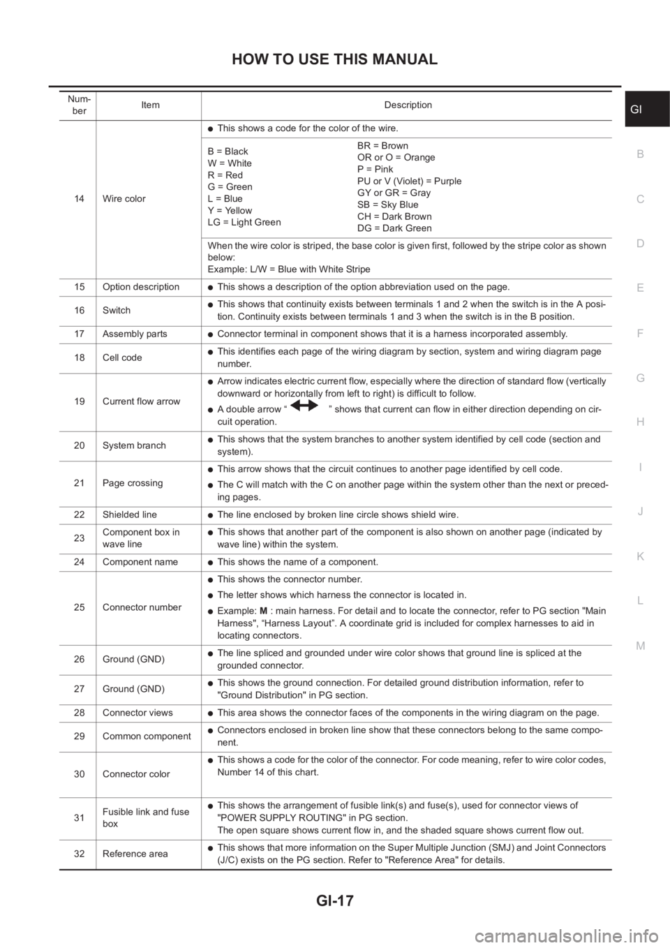
14 Wire color
●This shows a code for the color of the wire.
B = Black
W = White
R = Red
G = Green
L = Blue
Y = Yellow
LG = Light GreenBR = Brown
OR or O = Orange
P = Pink
PU or V (Violet) = Purple
GY or GR = Gray
SB = Sky Blue
CH = Dark Brown
DG = Dark Green
When the wire color is striped, the base color is given first, followed by the stripe color as shown
below:
Example: L/W = Blue with White Stripe
15 Option description
●This shows a description of the option abbreviation used on the page.
16 Switch
●This shows that continuity exists between terminals 1 and 2 when the switch is in the A posi-
tion. Continuity exists between terminals 1 and 3 when the switch is in the B position.
17 Assembly parts
●Connector terminal in component shows that it is a harness incorporated assembly.
18 Cell code
●This identifies each page of the wiring diagram by section, system and wiring diagram page
number.
19 Current flow arrow
●Arrow indicates electric current flow, especially where the direction of standard flow (vertically
downward or horizontally from left to right) is difficult to follow.
●A double arrow “ ” shows that current can flow in either direction depending on cir-
cuit operation.
20 System branch
●This shows that the system branches to another system identified by cell code (section and
system).
21 Page crossing
●This arrow shows that the circuit continues to another page identified by cell code.
●The C will match with the C on another page within the system other than the next or preced-
ing pages.
22 Shielded line
●The line enclosed by broken line circle shows shield wire.
23Component box in
wave line
●This shows that another part of the component is also shown on another page (indicated by
wave line) within the system.
24 Component name
●This shows the name of a component.
25 Connector number
●This shows the connector number.
●The letter shows which harness the connector is located in.
●Example: M : main harness. For detail and to locate the connector, refer to PG section "Main
Harness", “Harness Layout”. A coordinate grid is included for complex harnesses to aid in
locating connectors.
26 Ground (GND)
●The line spliced and grounded under wire color shows that ground line is spliced at the
grounded connector.
27 Ground (GND)
●This shows the ground connection. For detailed ground distribution information, refer to
"Ground Distribution" in PG section.
28 Connector views
●This area shows the connector faces of the components in the wiring diagram on the page.
29 Common component
●Connectors enclosed in broken line show that these connectors belong to the same compo-
nent.
30 Connector color
●This shows a code for the color of the connector. For code meaning, refer to wire color codes,
Number 14 of this chart.
31Fusible link and fuse
box
●This shows the arrangement of fusible link(s) and fuse(s), used for connector views of
"POWER SUPPLY ROUTING" in PG section.
The open square shows current flow in, and the shaded square shows current flow out.
32 Reference area
●This shows that more information on the Super Multiple Junction (SMJ) and Joint Connectors
(J/C) exists on the PG section. Refer to "Reference Area" for details. Num-
berItem Description
Page 35 of 3833
CONSULT-II CHECKING SYSTEM
GI-33
C
D
E
F
G
H
I
J
K
L
MB
GI
CONSULT-II CHECKING SYSTEMPFP:00000
DescriptionEAS000G8
●CONSULT-II is a hand-held type tester. When it is connected with a diagnostic connector equipped on the
vehicle side, it will communicate with the control unit equipped in the vehicle and then enable various
kinds of diagnostic tests.
●Refer to “CONSULT-II Software Operation Manual” for more information.
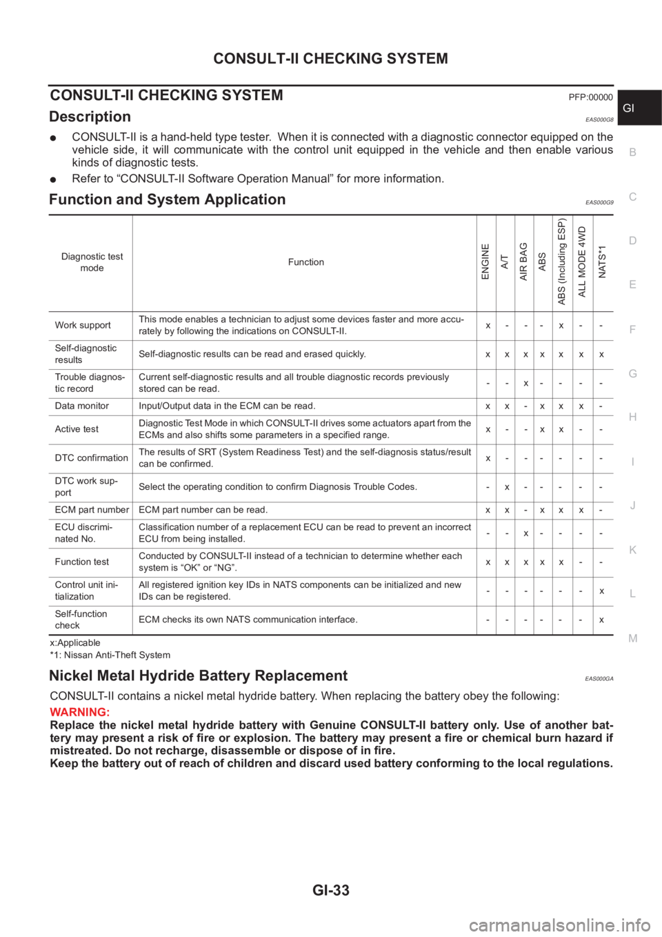
Function and System Application EAS000G9
x:Applicable
*1: Nissan Anti-Theft System
Nickel Metal Hydride Battery Replacement EAS000GA
CONSULT-II contains a nickel metal hydride battery. When replacing the battery obey the following:
WARNING:
Replace the nickel metal hydride battery with Genuine CONSULT-II battery only. Use of another bat-
tery may present a risk of fire or explosion. The battery may present a fire or chemical burn hazard if
mistreated. Do not recharge, disassemble or dispose of in fire.
Keep the battery out of reach of children and discard used battery conforming to the local regulations.
Diagnostic test
modeFunction
ENGINE
A/T
AIR BAG
ABS
ABS (Including ESP)
ALL MODE 4WD
NATS*1
Work supportThis mode enables a technician to adjust some devices faster and more accu-
rately by following the indications on CONSULT-II.x- -- x- -
Self-diagnostic
resultsSelf-diagnostic results can be read and erased quickly. x x x x x x x
Trouble diagnos-
tic recordCurrent self-diagnostic results and all trouble diagnostic records previously
stored can be read.--x----
Data monitor Input/Output data in the ECM can be read. x x - x x x -
Active testDiagnostic Test Mode in which CONSULT-II drives some actuators apart from the
ECMs and also shifts some parameters in a specified range.x- -xx- -
DTC confirmationThe results of SRT (System Readiness Test) and the self-diagnosis status/result
can be confirmed.x------
DTC work sup-
portSelect the operating condition to confirm Diagnosis Trouble Codes. -x-----
ECM part number ECM part number can be read. x x - x x x -
ECU discrimi-
nated No.Classification number of a replacement ECU can be read to prevent an incorrect
ECU from being installed.--x----
Function testConducted by CONSULT-II instead of a technician to determine whether each
system is “OK” or “NG”.xxxxx - -
Control unit ini-
tializationAll registered ignition key IDs in NATS components can be initialized and new
IDs can be registered.------x
Self-function
checkECM checks its own NATS communication interface. - - - - - - x
Page 68 of 3833

EM-18
[QR]
INTAKE MANIFOLD
5. Disconnect fuel hose quick connector on engine side.
●Using tool of quick connector release (here in after “release”),
perform the following steps to disconnect quick connector.
a. Remove quick connector cap.
b. With the sleeve side of release facing quick connector, install
release onto fuel tube.
c. Insert release into quick connector until sleeve contacts and
goes no further. Hold the release on that position.
CAUTION:
Inserting the release hard will not disconnect quick connec-
tor. Hold release where it contacts and goes no further.
d. Draw and pull out quick connector straight from fuel tube.
CAUTION:
●Pull quick connector holding A position in illustration.
●Do not pull with lateral force applied. O-ring inside quick connector may be damaged.
●Prepare container and cloth beforehand as fuel will leak out.
●Avoid fire and sparks.
●Be sure to cover openings of disconnected pipes with plug or plastic bag to avoid fuel leakage
and entry of foreign materials.
6. Disconnect fuel hose quick connector at vehicle piping side, perform as follows.
a. Remove quick connector cap.
b. Hold the sides of the connector, push in tubs and pull out the
tube. (The figure is shown for reference only.)
●If the connector and the tube are stuck together, push and pull
several times until they start to move. Then disconnect them
by pulling.
CAUTION:
●The quick connector can be disconnected when the
tabs are completely depressed. Do not twist it more
than necessary.
●Do not use any tools to disconnect the quick connec-
tor.
●Keep the resin tube away from heat. Be especially careful when welding near the tube.
●Prevent acid liquid such as battery electrolyte etc. from getting on the resin tube.
KBIA0268E
KBIA0702E
KBIA0701E
SFE562A
Page 91 of 3833

TIMING CHAIN
EM-41
[QR]
C
D
E
F
G
H
I
J
K
L
MA
EM
INSPECTION AFTER REMOVAL
Timing Chain
Check timing chain for cracks or serious wear. If a malfunction is
detected, replace it.
Balancer Unit Mounting Bolt Outer Diameter.
●Measure outer diameters (d1, d2) at the two positions shown in
the figure.
●Measure d2 within the range A.
●If the value difference (d1 – d2) exceeds the limit (a dimension
difference is large), replace it with a new one.
INSTALLATION
NOTE:
●The figure shows the relationship between the mating mark on
each timing chain and that on the corresponding sprocket, with
the components installed.
●Because of parallel manufacture, there are two types of mark
(link colors) for timing chain.
1. Make suer that crankshaft key points straight up.
PBIC0282E
Limit: 0.15 mm (0. 0059in) or more.
PBIC1137E
SBIA0265E
Page 110 of 3833

EM-60
[QR]
CYLINDER HEAD
●If the engine speed is out of specified range, check battery liquid for proper gravity. Check engine
speed again with normal battery gravity.
●If compression pressure is below minimum value, check valve clearances and parts associated with
combustion chamber (Valve, valve seat, piston, piston ring, cylinder bore, cylinder head, cylinder head
gasket). After the checking, measure compression pressure again.
●If some cylinders have low compression pressure, pour small amount of engine oil into the spark plug
hole of the cylinder to re-check it for compression.
–If the added engine oil improves the compression, the piston rings may be worn out or damaged. Check
the piston rings and replace if necessary.
–If the compression pressure remains at low level despite the addition of engine oil, the valves may be
malfunctioning. Check the valves for damage. Replace the valve or valve seat accordingly.
●If two adjacent cylinders have respectively low compression pressure and their compression remains
low even after the addition of engine oil, the gaskets are leaking. In such a case, replace the cylinder
head gaskets.
8. Install spark plug, ignition coil and harness connectors.
Removal and InstallationEBS00KNQ
REMOVAL
1. Release fuel pressure. Refer to EC-775, "FUEL PRESSURE RELEASE" [QR20DE (WITH EURO-OBD)],
EC-1139, "
FUEL PRESSURE RELEASE" [QR20DE (WITHOUT EURO-OBD)], EC-42, "FUEL PRES-
SURE RELEASE" [QR25DE (WITH EURO-OBD)] or EC-452, "FUEL PRESSURE RELEASE" [QR25DE
(WITHOUT EURO-OBD)].
2. Drain engine coolant and engine oil.
3. Remove the following components and related parts.
●Engine hood and engine undercover.
●Air cleaner case and air duct assembly; Refer to EM-14, "AIR CLEANER AND AIR DUCT" .
●Ignition coils; Refer to EM-29, "IGNITION COIL" .
●Rocker cover; Refer to EM-35, "ROCKER COVER" .
●Engine coolant reservoir tank
●Drive belt; Refer to EM-12, "REMOVAL" .
●Alternator
●Drive belt auto-tensioner; Refer to EM-13, "REMOVAL" .
●Exhaust front tube; Refer to EX-2, "Removal and Installation" .
●Exhaust manifold; Refer to EM-24, "EXHAUST MANIFOLD AND THREE WAY CATALYST" .
KBIA0250E
1. Cylinder head assembly 2. Cylinder head gasket 3. Cylinder head bolt
Page 125 of 3833

CYLINDER BLOCK
EM-75
[QR]
C
D
E
F
G
H
I
J
K
L
MA
EM
●A commercial engine stand can be used.
NOTE:
This example is an engine stand for holding at transaxle
mounting side with the flywheel or drive plate removed.
3. Drain engine oil and engine coolant from inside of engine.
4. Remove the following components and associated parts.
●Exhaust manifold and three way catalyst assembly; Refer to
EM-24, "
EXHAUST MANIFOLD AND THREE WAY CATA-
LYST" .
●Intake manifold collector; Refer to EM-16, "INTAKE MANI-
FOLD" .
●Intake manifold and fuel tube assembly; Refer to EM-16, "INTAKE MANIFOLD" .
●Ignition coil; Refer to EM-29, "IGNITION COIL" .
●Rocker cover; Refer to EM-35, "ROCKER COVER" .
●Oil pan and oil strainer; Refer to EM-26, "OIL PAN AND OIL STRAINER" .
●Front cover, timing chain and balancer unit; Refer to EM-37, "TIMING CHAIN" .
●Camshaft; Refer to EM-46, "CAMSHAFT" .
●Cylinder head; Refer to EM-59, "CYLINDER HEAD" .
5. Remove knock sensor.
CAUTION:
Carefully handle the sensor avoiding shocks.
6. Remove crankshaft position sensor (POS).
CAUTION:
●Avoid impacts such as a dropping.
●Do not disassemble.
●Keep it away from metal particles.
●Do not place sensor close to magnetic materials.
7. Remove flywheel (M/T model) or drive plate (A/T model). Fix crankshaft with a stopper plate, and remove
mounting bolts.
Torx bit (size T55): Flywheel (M/T model)
Torx socket (size T55): Drive plate (A/T model)
CAUTION:
Be careful not to damage contact surface for the clutch disc
of the flywheel.
NOTE:
The flywheels, two block construction, allows movement in
response to transmission side pressure, or when twisted in its
rotational direction. Therefore, some amount of noise is normal.
PBIC0085E
SBIA0273E
KBIA0062E
Page 126 of 3833

EM-76
[QR]
CYLINDER BLOCK
8. Remove pilot converter using Tool or suitable tool. (A/T model)
NOTE:
M/T models have no pilot push.
9. Remove the piston and connecting rod assembly.
a. Position the crankshaft pin corresponding to the connecting rod
to be removed onto the bottom dead center.
b. Remove the connecting rod cap.
c. Using a hammer handle or similar tool, push the piston and con-
necting rod assembly out to the cylinder head side.
●Before removing the piston and connecting rod assembly,
check the connecting rod side clearance. Refer to EM-89,
"CONNECTING ROD SIDE CLEARANCE" .
10. Remove the connecting rod bearings.
CAUTION:
When removing them, note the installation position. Keep them in the correct order.
11. Remove the piston rings form the piston.
●Use a piston ring expander.
CAUTION:
●When removing the piston rings, be careful not to dam-
age the piston.
●Be careful not to damage piston rings by expanding
them excessively.
●Before removing the piston rings, check the piston ring
side clearance. Refer to EM-90, "
PISTON RING SIDE
CLEARANCE" .
12. Remove the piston from the connecting rod as follows.
a. Using a snap ring pliers, remove the snap ring.
SBIA0274E
PBIC0259E
PBIC0087E
PBIC0260E
Page 131 of 3833

CYLINDER BLOCK
EM-81
[QR]
C
D
E
F
G
H
I
J
K
L
MA
EM
12. Install the connecting rod bearings to the connecting rod and the
connecting rod cap.
●When installing the connecting rod bearings, apply engine oil
to the bearing surface (inside). Do not apply engine oil to the
back surface, but thoroughly clean it.
●When installing, align the connecting rod bearing stopper pro-
trusion with the notch of the connecting rod to install.
●Check the oil holes on the connecting rod and those on the
corresponding bearing are aligned.
13. Install the piston and connecting rod assembly to the crankshaft.
●Position the crankshaft pin corresponding to the connecting
rod to be installed onto the bottom dead center.
●Apply engine oil sufficiently to the cylinder bore, piston and
crankshaft pin.
●Match the cylinder position with the cylinder No. on the con-
necting rod to install.
●Using a piston ring compressor, install the piston with the front
mark on the piston crown facing the front of the engine.
CAUTION:
Be careful not to damage the cylinder wall and crankshaft
pin, resulting from an interference of the connecting rod big end.
14. Install the connecting rod cap.
●Match the stamped cylinder number marks on the connecting
rod with those on the cap to install.
15. Tighten the connecting rod bolt as follows.
a. Apply engine oil to the threads and seats of the connecting rod
bolts.
b. Tighten bolts to 18.6 to 20.6 N·m (1.9 to 2.1 kg-m, 14 to 15 ft-lb).
c. Put mating (with paint) on each bolt and connecting rod cap, all
in the same direction (when using a protractor).
d. Then tighten all bolts 90 to 95 degrees clockwise (target: 90
degrees) (Angle tightening).
CAUTION:
Always use either an angle wrench or protractor. Avoid
tightening based on visual check alone.
●After tightening the bolt, make sure that the crankshaft rotates smoothly.
●Check the connecting rod side clearance. Refer to EM-89, "CONNECTING ROD SIDE CLEARANCE" .
PBIC0266E
PBIC0267E
SBIA0282E
KBIA0068E